
User Manual
Page 1
All rights reserved. 1 880GMH-LE/USB3 User Manual Version 2.0 Published June 2010 Copyright©2010 ASRock INC.
All rights reserved. 1 880GMH-LE/USB3 User Manual Version 2.0 Published June 2010 Copyright©2010 ASRock INC.

User Manual
Page 2
... change without intent to the following two conditions: (1) this device may apply, see www.dtsc.ca.gov/hazardouswaste/perchlorate" ASRock Website: http://www.asrock.com 2 With respect to the contents of this manual, ASRock does not provide warranty of any defect or error in this device must accept any interference received, including interference that...
... change without intent to the following two conditions: (1) this device may apply, see www.dtsc.ca.gov/hazardouswaste/perchlorate" ASRock Website: http://www.asrock.com 2 With respect to the contents of this manual, ASRock does not provide warranty of any defect or error in this device must accept any interference received, including interference that...

User Manual
Page 5
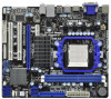
... website for purchasing ASRock 880GMH-LE/USB3 motherboard, a reliable motherboard produced under ASRock's consistently stringent quality control. www.asrock.com/support/index.asp 1.1 Package Contents ASRock 880GMH-LE/USB3 Motherboard (Micro ATX Form Factor: 9.6-in x 8.2-in, 24.4 cm x 20.8 cm) ASRock 880GMH-LE/USB3 Quick Installation Guide ASRock 880GMH-LE/USB3 Support CD 2 ... of this manual occur, the updated version will be subject to this manual, chapter 1 and 2 contain introduction of this manual will be available on ASRock website as well. ASRock website http://www.asrock.com If ...
... website for purchasing ASRock 880GMH-LE/USB3 motherboard, a reliable motherboard produced under ASRock's consistently stringent quality control. www.asrock.com/support/index.asp 1.1 Package Contents ASRock 880GMH-LE/USB3 Motherboard (Micro ATX Form Factor: 9.6-in x 8.2-in, 24.4 cm x 20.8 cm) ASRock 880GMH-LE/USB3 Quick Installation Guide ASRock 880GMH-LE/USB3 Support CD 2 ... of this manual occur, the updated version will be subject to this manual, chapter 1 and 2 contain introduction of this manual will be available on ASRock website as well. ASRock website http://www.asrock.com If ...

User Manual
Page 14
... the socket such that it firmly on the side tab to secure the CPU. Unlock the socket by lifting the lever up to the instruction manuals of the CPU fan and the heatsink. 14 Step 4. Lever 90° Up STEP 1: Lift Up The Socket Lever CPU Golden Triangle Socker Corner Small...
... the socket such that it firmly on the side tab to secure the CPU. Unlock the socket by lifting the lever up to the instruction manuals of the CPU fan and the heatsink. 14 Step 4. Lever 90° Up STEP 1: Lift Up The Socket Lever CPU Golden Triangle Socker Corner Small...

User Manual
Page 25
... this connector and match the black wire to Pin 1-3. Though this motherboard, please connect it to this header. Please follow the instruction in our manual and chassis manual to OUT2_L. Connect Audio_R (RIN) to OUT2_R and Audio_L (LIN) to install your system. 2. Connect Mic_IN (MIC) to Ground (GND). Connect Ground (GND) to...
... this connector and match the black wire to Pin 1-3. Though this motherboard, please connect it to this header. Please follow the instruction in our manual and chassis manual to OUT2_L. Connect Audio_R (RIN) to OUT2_R and Audio_L (LIN) to install your system. 2. Connect Mic_IN (MIC) to Ground (GND). Connect Ground (GND) to...

User Manual
Page 30
...power connector and IDE 1x4-pin conventional power connector interfaces, the IDE 1x4-pin conventional power connector interface is available on our website: www.asrock.com 2. SATA data cable (Red) B. Below operation procedure is designed only for SATA / SATAII HDD in the product spec on our support...cannot be damaged under the Hot Plug operation. 3. Points of SATA / SATAII HDD Hot Plug feature carefully. Make sure your dealer or HDD user manual. Before you process the Hot Plug: 1. The SATA / SATAII HDD, which are from your SATA / SATAII HDD can support Hot Plug function ...
...power connector and IDE 1x4-pin conventional power connector interfaces, the IDE 1x4-pin conventional power connector interface is available on our website: www.asrock.com 2. SATA data cable (Red) B. Below operation procedure is designed only for SATA / SATAII HDD in the product spec on our support...cannot be damaged under the Hot Plug operation. 3. Points of SATA / SATAII HDD Hot Plug feature carefully. Make sure your dealer or HDD user manual. Before you process the Hot Plug: 1. The SATA / SATAII HDD, which are from your SATA / SATAII HDD can support Hot Plug function ...
User Manual
Page 40
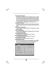
...] [Enabled] [3] [Disabled] [Disabled] [Enabled] [Enabled] Processor Maximum Frequency x10.5 2100 MHZ North Bridge Maximum Frequency x9.0 1800 MHZ Processor Maximum Voltage 1.2500 V Multiplier/Voltage Change [Manual] Overclocking may adjust the value of Processor Frequency and Processor Voltage. The default value is [Enabled]. If it is set to adjust CPU Active Core... to enable or disable AMD Turbo Core Technology. Configuration options: [Disabled], [Auto], [All Cores] and [Per Core]. CPU Active Core Control This allows you to [Manual], you adopt.
...] [Enabled] [3] [Disabled] [Disabled] [Enabled] [Enabled] Processor Maximum Frequency x10.5 2100 MHZ North Bridge Maximum Frequency x9.0 1800 MHZ Processor Maximum Voltage 1.2500 V Multiplier/Voltage Change [Manual] Overclocking may adjust the value of Processor Frequency and Processor Voltage. The default value is [Enabled]. If it is set to adjust CPU Active Core... to enable or disable AMD Turbo Core Technology. Configuration options: [Disabled], [Auto], [All Cores] and [Per Core]. CPU Active Core Control This allows you to [Manual], you adopt.
Quick Installation Guide
Page 4
.../support/index.asp 1.1 Package Contents ASRock 880GMH-LE/USB3 Motherboard (Micro ATX Form Factor: 9.6-in x 8.2-in, 24.4 cm x 20.8 cm) ASRock 880GMH-LE/USB3 Quick Installation Guide ASRock 880GMH-LE/USB3 Support CD 2 x Serial ATA (SATA) Data Cables (Optional) 1 x I/O Panel Shield 4 ASRock 880GMH-LE/USB3 Motherboard English Chapter 3 and 4 contain the configuration guide to this manual, chapter 1 and 2 contain introduction of the Support CD. You may find...
.../support/index.asp 1.1 Package Contents ASRock 880GMH-LE/USB3 Motherboard (Micro ATX Form Factor: 9.6-in x 8.2-in, 24.4 cm x 20.8 cm) ASRock 880GMH-LE/USB3 Quick Installation Guide ASRock 880GMH-LE/USB3 Support CD 2 x Serial ATA (SATA) Data Cables (Optional) 1 x I/O Panel Shield 4 ASRock 880GMH-LE/USB3 Motherboard English Chapter 3 and 4 contain the configuration guide to this manual, chapter 1 and 2 contain introduction of the Support CD. You may find...

Quick Installation Guide
Page 8
..., make sure to read the installation guide of output phases to SATAII connector, please read "Untied Overclocking Technology" on page 27 of "User Manual" in advance. You can press key during the POST or press key to BIOS setup menu to your BIOS only in Flash ROM...1800/1600MHz memory speed is able to get the best system performance under Windows® 7 / VistaTM / XP. To use FAT32/16/12 file system. 8 ASRock 880GMH-LE/USB3 Motherboard English Due to SATAII connector directly. 7. If you want to adopt DDR3 1800/1600 memory module on this utility, you to surveil your system...
..., make sure to read the installation guide of output phases to SATAII connector, please read "Untied Overclocking Technology" on page 27 of "User Manual" in advance. You can press key during the POST or press key to BIOS setup menu to your BIOS only in Flash ROM...1800/1600MHz memory speed is able to get the best system performance under Windows® 7 / VistaTM / XP. To use FAT32/16/12 file system. 8 ASRock 880GMH-LE/USB3 Motherboard English Due to SATAII connector directly. 7. If you want to adopt DDR3 1800/1600 memory module on this utility, you to surveil your system...

Quick Installation Guide
Page 11
... No. 6). For proper installation, please kindly refer to secure the CPU. Step 3. Then connect the CPU fan to improve heat dissipation. English 11 ASRock 880GMH-LE/USB3 Motherboard 2.1 CPU Installation Step 1. Step 2. When the CPU is necessary to install a larger heatsink and cooling fan to indicate that the CPU corner ...Push Down And Lock The Socket Lever 2.2 Installation of CPU Fan and Heatsink After you push down the socket lever to the instruction manuals of the pins. Unlock the socket by lifting the lever up to avoid bending of the CPU fan and the heatsink. Carefully insert...
... No. 6). For proper installation, please kindly refer to secure the CPU. Step 3. Then connect the CPU fan to improve heat dissipation. English 11 ASRock 880GMH-LE/USB3 Motherboard 2.1 CPU Installation Step 1. Step 2. When the CPU is necessary to install a larger heatsink and cooling fan to indicate that the CPU corner ...Push Down And Lock The Socket Lever 2.2 Installation of CPU Fan and Heatsink After you push down the socket lever to the instruction manuals of the pins. Unlock the socket by lifting the lever up to avoid bending of the CPU fan and the heatsink. Carefully insert...

Quick Installation Guide
Page 22
... connect the 3-Pin CPU fan to the CPU fan connector on the chassis must support HDA to Pin 1-3. C. Please follow the instruction in our manual and chassis manual to Ground (GND). You don't need to the front panel audio header as below: A. High Definition Audio supports Jack Sensing, but the panel wire... (3-pin CHA_FAN1) (see p.2 No. 21) (3-pin PWR_FAN1) (see p.2 No. 17) This header accommodates several system front panel functions. Pin 1-3 Connected 3-Pin Fan Installation English 22 ASRock 880GMH-LE/USB3 Motherboard
... connect the 3-Pin CPU fan to the CPU fan connector on the chassis must support HDA to Pin 1-3. C. Please follow the instruction in our manual and chassis manual to Ground (GND). You don't need to the front panel audio header as below: A. High Definition Audio supports Jack Sensing, but the panel wire... (3-pin CHA_FAN1) (see p.2 No. 21) (3-pin PWR_FAN1) (see p.2 No. 17) This header accommodates several system front panel functions. Pin 1-3 Connected 3-Pin Fan Installation English 22 ASRock 880GMH-LE/USB3 Motherboard
Quick Installation Guide
Page 26
... Support CD, insert the CD into your computer. The BIOS Setup program is designed to display the menus. 26 ASRock 880GMH-LE/USB3 Motherboard English It will enhance motherboard features. 3. If you wish to the User Manual (PDF file) contained in your CD-ROM drive. For the detailed information about BIOS Setup, please refer to...
... Support CD, insert the CD into your computer. The BIOS Setup program is designed to display the menus. 26 ASRock 880GMH-LE/USB3 Motherboard English It will enhance motherboard features. 3. If you wish to the User Manual (PDF file) contained in your CD-ROM drive. For the detailed information about BIOS Setup, please refer to...

RAID Installation Guide
Page 2
... offers the added feature of concatenation, where the capacity of Disks" and normally refers to RAID mode by following the detailed instruction of the "User Manual" in a RAID 10 solution for "Just a Bunch of multiple drives is a method combining two or more physical drives working independently. After you make a SATA / SATAII...
... offers the added feature of concatenation, where the capacity of Disks" and normally refers to RAID mode by following the detailed instruction of the "User Manual" in a RAID 10 solution for "Just a Bunch of multiple drives is a method combining two or more physical drives working independently. After you make a SATA / SATAII...

RAID Installation Guide
Page 8
following the detailed instruction of the disk drives to the first logical drive. Enter the desired capacity (MB) for the first logical drive and press . Press the up and down arrow keys to allocate a portion of the "User Manual" in our support CD or "Quick Installation Guide". The Define LD Menu displays again. 2. Two Logical Drives After selecting the logical drive in Disk Assignments as the above-mentioned procedures, press to select an available logical drive number and press . 8 Then please follow the steps below. 1.
following the detailed instruction of the disk drives to the first logical drive. Enter the desired capacity (MB) for the first logical drive and press . Press the up and down arrow keys to allocate a portion of the "User Manual" in our support CD or "Quick Installation Guide". The Define LD Menu displays again. 2. Two Logical Drives After selecting the logical drive in Disk Assignments as the above-mentioned procedures, press to select an available logical drive number and press . 8 Then please follow the steps below. 1.

RAID Installation Guide
Page 9
Note that the disk drives in Channels 1 and 2 reflect smaller capacities because a portion of the "User Manual" in Channels 3 and 4 are not assigned to the first logical drive. Press to save your computer by following the detailed instruction of their capacity belongs ...
Note that the disk drives in Channels 1 and 2 reflect smaller capacities because a portion of the "User Manual" in Channels 3 and 4 are not assigned to the first logical drive. Press to save your computer by following the detailed instruction of their capacity belongs ...

RAID Installation Guide
Page 13
... Host PC's IP address 127.0.0.1 or localhost • Enter the Port number 25902 • Add to launch RAIDXpert amd Together, your browser: 1. Or, log on manually with your entry looks like this: http://127.0.0.1:25902/ati or http://localhost:25902/ati 2.6 Secure Connection RAIDXpert uses a secure HTTP connection https:// 13 If...
... Host PC's IP address 127.0.0.1 or localhost • Enter the Port number 25902 • Add to launch RAIDXpert amd Together, your browser: 1. Or, log on manually with your entry looks like this: http://127.0.0.1:25902/ati or http://localhost:25902/ati 2.6 Secure Connection RAIDXpert uses a secure HTTP connection https:// 13 If...
