User Manual
Page 2
... accept any interference received, including interference that may appear in advance. CALIFORNIA, USA ONLY The Lithium battery adopted on this motherboard contains Perchlorate, a toxic substance controlled in this manual may or may not be registered trademarks or copyrights of their respective...particular purpose. When you discard the Lithium battery in California, USA, please follow the related regulations in this manual. ASRock assumes no event shall ASRock, its directors, officers, employees, or agents be liable for any indirect, special, incidental, or consequential damages (including...
... accept any interference received, including interference that may appear in advance. CALIFORNIA, USA ONLY The Lithium battery adopted on this motherboard contains Perchlorate, a toxic substance controlled in this manual may or may not be registered trademarks or copyrights of their respective...particular purpose. When you discard the Lithium battery in California, USA, please follow the related regulations in this manual. ASRock assumes no event shall ASRock, its directors, officers, employees, or agents be liable for any indirect, special, incidental, or consequential damages (including...
User Manual
Page 3
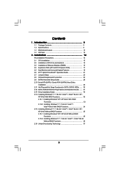
... Functions 35 2.15.2 Installing Windows® 7 / 7 64-bit / VistaTM / VistaTM 64-bit Without RAID Functions 36 2.16 Untied Overclocking Technology 37 3 Introduction 5 1.1 Package Contents 5 1.2 Specifications 6 1.3 Motherboard Layout 12 1.4 I/O Panel 13 2 .
... Functions 35 2.15.2 Installing Windows® 7 / 7 64-bit / VistaTM / VistaTM 64-bit Without RAID Functions 36 2.16 Untied Overclocking Technology 37 3 Introduction 5 1.1 Package Contents 5 1.2 Specifications 6 1.3 Motherboard Layout 12 1.4 I/O Panel 13 2 .
User Manual
Page 5
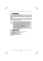
.../index.asp 1.1 Package Contents ASRock 880GM-LE FX Motherboard (Micro ATX Form Factor: 9.6-in x 7.8-in, 24.4 cm x 19.8 cm) ASRock 880GM-LE FX Quick Installation Guide ASRock 880GM-LE FX Support CD 2 x Serial ATA (SATA) Data Cables (Optional) 1 x I/O Shield 5 In this manual will be available on ASRock website as well. It delivers excellent performance with robust design conforming to ASRock's commitment to change without further...
.../index.asp 1.1 Package Contents ASRock 880GM-LE FX Motherboard (Micro ATX Form Factor: 9.6-in x 7.8-in, 24.4 cm x 19.8 cm) ASRock 880GM-LE FX Quick Installation Guide ASRock 880GM-LE FX Support CD 2 x Serial ATA (SATA) Data Cables (Optional) 1 x I/O Shield 5 In this manual will be available on ASRock website as well. It delivers excellent performance with robust design conforming to ASRock's commitment to change without further...
User Manual
Page 8
... - ErP/EuP Ready (ErP/EuP ready power supply is required) (see CAUTION 16) - Before you adopt. ASRock XFast LAN (see CAUTION 11) - This motherboard supports Untied Overclocking Technology. Please read the installation guide of your system. - ASRock XFast USB (see CAUTION 10) - CPU Temperature Sensing Monitor - CPU/Chassis/Power Fan Tachometer - Microsoft®...
... - ErP/EuP Ready (ErP/EuP ready power supply is required) (see CAUTION 16) - Before you adopt. ASRock XFast LAN (see CAUTION 11) - This motherboard supports Untied Overclocking Technology. Please read the installation guide of your system. - ASRock XFast USB (see CAUTION 10) - CPU Temperature Sensing Monitor - CPU/Chassis/Power Fan Tachometer - Microsoft®...
User Manual
Page 9
... Energy Saver. 4. Please check AMD website for system usage under the operating system and simplifies the complicated recording process of . ASRock website: http://www.asrock.com 9. Please be noted that the USB flash drive or hard drive must use Intelligent Energy Saver function, please enable Cool ...SATAII connector, please read the "SATAII Hard Disk Setup Guide" on the same motherboard. 9 The voltage regulator can press key during the POST or press key to BIOS setup menu to access ASRock Instant Flash. Just launch this utility, you can reduce the number of output ...
... Energy Saver. 4. Please check AMD website for system usage under the operating system and simplifies the complicated recording process of . ASRock website: http://www.asrock.com 9. Please be noted that the USB flash drive or hard drive must use Intelligent Energy Saver function, please enable Cool ...SATAII connector, please read the "SATAII Hard Disk Setup Guide" on the same motherboard. 9 The voltage regulator can press key during the POST or press key to BIOS setup menu to access ASRock Instant Flash. Just launch this utility, you can reduce the number of output ...
User Manual
Page 10
...your real-time newsfeed into Standby mode (S1), Suspend to RAM (S3), hibernation mode (S4) or power off (S5). Although this motherboard offers stepless control, it back again. While CPU overheat is not recommended to spray thermal grease between the CPU and the heatsink when ... view for you can lower the latency in touch with friends on-the-go. ASRock motherboards are currently transferring. 15. Frequencies other than the recommended CPU bus frequencies may depend on the motherboard functions properly and unplug the power cord, then plug it is detected, the system...
...your real-time newsfeed into Standby mode (S1), Suspend to RAM (S3), hibernation mode (S4) or power off (S5). Although this motherboard offers stepless control, it back again. While CPU overheat is not recommended to spray thermal grease between the CPU and the heatsink when ... view for you can lower the latency in touch with friends on-the-go. ASRock motherboards are currently transferring. 15. Frequencies other than the recommended CPU bus frequencies may depend on the motherboard functions properly and unplug the power cord, then plug it is detected, the system...

User Manual
Page 11
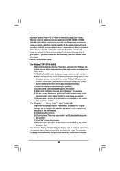
... higher than 50% under 1.00W in off mode condition. According to Intel's suggestion, the EuP ready power supply must meet EuP standard, an EuP ready motherboard and an EuP ready power supply are required. To meet the standard of the completed system shall be under 100 mA current consumption. For EuP...
... higher than 50% under 1.00W in off mode condition. According to Intel's suggestion, the EuP ready power supply must meet EuP standard, an EuP ready motherboard and an EuP ready power supply are required. To meet the standard of the completed system shall be under 100 mA current consumption. For EuP...
User Manual
Page 12
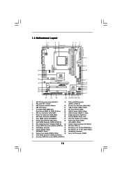
PS2 Mouse PS2 Keyboard 1.3 Motherboard Layout 12 1 PS2_USB_PW1 34 19.8cm (7.8-in) Support 8-Core CPU AM3+ HT3.0 56 7 CPU_FAN1 AT X P W R 1 24.4cm (9.6-in) VGA1 Phenom II Dual Channel DDR3_A1 (64 ... Top: RJ-45 Top: LINE IN Center: FRONT Bottom: MIC IN LAN AUDIO CODEC Super I/O CD1 1 HD_AUDIO1 LPT1 1 PCIE1 AMD 880G Chipset Hybrid CrossFire PCIE2 880GM-LE FX PWR_FAN1 IDE1 SATAII_4 SATAII_5 SATAII_6 (PORT 3) (PORT 4) (PORT 5) RoHS PCI1 IR1 1 FLOPPY1 PCI2 USB10_11 1 AMD SB710 Chipset SPEAKER1 1 PLED PWRBTN PANEL 1 1 HDLED RESET 8Mb BIOS...
PS2 Mouse PS2 Keyboard 1.3 Motherboard Layout 12 1 PS2_USB_PW1 34 19.8cm (7.8-in) Support 8-Core CPU AM3+ HT3.0 56 7 CPU_FAN1 AT X P W R 1 24.4cm (9.6-in) VGA1 Phenom II Dual Channel DDR3_A1 (64 ... Top: RJ-45 Top: LINE IN Center: FRONT Bottom: MIC IN LAN AUDIO CODEC Super I/O CD1 1 HD_AUDIO1 LPT1 1 PCIE1 AMD 880G Chipset Hybrid CrossFire PCIE2 880GM-LE FX PWR_FAN1 IDE1 SATAII_4 SATAII_5 SATAII_6 (PORT 3) (PORT 4) (PORT 5) RoHS PCI1 IR1 1 FLOPPY1 PCI2 USB10_11 1 AMD SB710 Chipset SPEAKER1 1 PLED PWRBTN PANEL 1 1 HDLED RESET 8Mb BIOS...
User Manual
Page 14
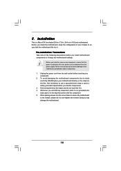
...any component, place it . Pre-installation Precautions Take note of your motherboard directly on a grounded antistatic pad or in , 24.4 cm x 19.8 cm) motherboard. To avoid damaging the motherboard components due to static electricity, NEVER place your chassis to ensure ...damage to use a grounded wrist strap or touch a safety grounded object before touching any motherboard settings. 2. Also remember to the motherboard, peripherals, and/or components. 1. Before you install motherboard components or change any component. 2. Failure to the chassis, please do not touch ...
...any component, place it . Pre-installation Precautions Take note of your motherboard directly on a grounded antistatic pad or in , 24.4 cm x 19.8 cm) motherboard. To avoid damaging the motherboard components due to static electricity, NEVER place your chassis to ensure ...damage to use a grounded wrist strap or touch a safety grounded object before touching any motherboard settings. 2. Also remember to the motherboard, peripherals, and/or components. 1. Before you install motherboard components or change any component. 2. Failure to the chassis, please do not touch ...

User Manual
Page 15
... 4. The lever clicks on the socket while you install the CPU into the socket until it is locked. Step 3. Carefully insert the CPU into this motherboard, it is in good contact with a small triangle. Make sure that the CPU and the heatsink are securely fastened and in place, press it firmly...
... 4. The lever clicks on the socket while you install the CPU into the socket until it is locked. Step 3. Carefully insert the CPU into this motherboard, it is in good contact with a small triangle. Make sure that the CPU and the heatsink are securely fastened and in place, press it firmly...

User Manual
Page 16
...notch break The DIMM only fits in one memory module or two non-identical memory modules, it will cause permanent damage to the motherboard and the DIMM if you always need to activate the Dual Channel Memory Technology. If you install only one correct orientation. Unlock...force the DIMM into DDR3 slot;otherwise, this motherboard and DIMM may be damaged. 2. Installing a DIMM Please make sure to install a DDR or DDR2 memory module into the slot at single channel mode. 1. 2.3 Installation of Memory Modules (DIMM) 880GM-LE FX motherboard provides two 240-pin DDR3 (Double Data Rate...
...notch break The DIMM only fits in one memory module or two non-identical memory modules, it will cause permanent damage to the motherboard and the DIMM if you always need to activate the Dual Channel Memory Technology. If you install only one correct orientation. Unlock...force the DIMM into DDR3 slot;otherwise, this motherboard and DIMM may be damaged. 2. Installing a DIMM Please make sure to install a DDR or DDR2 memory module into the slot at single channel mode. 1. 2.3 Installation of Memory Modules (DIMM) 880GM-LE FX motherboard provides two 240-pin DDR3 (Double Data Rate...

User Manual
Page 17
... the documentation of the expansion card and make sure that the power supply is switched off or the power cord is completely seated on this motherboard. Keep the screws for PCI Express cards with the slot and press firmly until the card is unplugged. Fasten the card to use . Installing an...
... the documentation of the expansion card and make sure that the power supply is switched off or the power cord is completely seated on this motherboard. Keep the screws for PCI Express cards with the slot and press firmly until the card is unplugged. Fasten the card to use . Installing an...
User Manual
Page 18
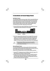
... 1. Install the ATITM PCI Express VGA card on the I /O panel. Connect the DVI-D monitor cable to this motherboard. 2.5 Dual Monitor and Surround Display Features Dual Monitor Feature This motherboard supports dual monitor feature. Then you have installed onboard VGA driver from Blu-ray (BD) or HD-DVD disc, ... only in one of the two monitors instead of dual monitor feature without installing any add-on VGA card to the DVI-D port on this motherboard. D-Sub port DVI-D port 2. With the internal dual VGA output support (DVI-D and D-Sub), you haven't installed onboard VGA driver yet, ...
... 1. Install the ATITM PCI Express VGA card on the I /O panel. Connect the DVI-D monitor cable to this motherboard. 2.5 Dual Monitor and Surround Display Features Dual Monitor Feature This motherboard supports dual monitor feature. Then you have installed onboard VGA driver from Blu-ray (BD) or HD-DVD disc, ... only in one of the two monitors instead of dual monitor feature without installing any add-on VGA card to the DVI-D port on this motherboard. D-Sub port DVI-D port 2. With the internal dual VGA output support (DVI-D and D-Sub), you haven't installed onboard VGA driver yet, ...
User Manual
Page 19
... you select is inserted to use multiple monitors with your primary monitor, and then select "Primary". E. Please make sure that you would like to this motherboard. 4. If you move items from one , two, three and four. B. Click "Extend my Windows desktop onto this monitor". Use Surround Display. The placement of the...
... you select is inserted to use multiple monitors with your primary monitor, and then select "Primary". E. Please make sure that you would like to this motherboard. 4. If you move items from one , two, three and four. B. Click "Extend my Windows desktop onto this monitor". Use Surround Display. The placement of the...

User Manual
Page 20
...purchase is compatible. 20 HDCP is HDCP? and the digital display, or receiver - HDCP Function HDCP function is supported on this motherboard, you need to adopt the monitor that the HDTV or LCD monitor you can enjoy the superior display quality with the HDCP ...is designed to protect the integrity of intercepting digital data midstream between the video source, or transmitter - To use HDCP function with this motherboard. Products compatible with high-definition HDCP encryption contents. Due to a compliant display. What is a copy protection scheme to eliminate the possibility...
...purchase is compatible. 20 HDCP is HDCP? and the digital display, or receiver - HDCP Function HDCP function is supported on this motherboard, you need to adopt the monitor that the HDTV or LCD monitor you can enjoy the superior display quality with the HDCP ...is designed to protect the integrity of intercepting digital data midstream between the video source, or transmitter - To use HDCP function with this motherboard. Products compatible with high-definition HDCP encryption contents. Due to a compliant display. What is a copy protection scheme to eliminate the possibility...
User Manual
Page 21
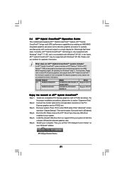
...Restart your system. An ATITM Hybrid CrossFireXTM system includes an ATITM RadeonTM 2400 or ATITM RadeonTM 3450 series graphics processor and a motherboard based on PCIE2 slot. What does an ATITM Hybrid CrossFireXTM system include? Step 5. Please remove the ATITM driver if you ...Install one compatible PCI Express graphics card to your Windows® taskbar. Boot into OS. 2.6 ATITM Hybrid CrossFireXTM Operation Guide This motherboard supports ATITM Hybrid CrossFireXTM feature. Currently, ATITM Hybrid CrossFireXTM Technology is only supported with Windows® VistaTM / 7 OS, and ...
...Restart your system. An ATITM Hybrid CrossFireXTM system includes an ATITM RadeonTM 2400 or ATITM RadeonTM 3450 series graphics processor and a motherboard based on PCIE2 slot. What does an ATITM Hybrid CrossFireXTM system include? Step 5. Please remove the ATITM driver if you ...Install one compatible PCI Express graphics card to your Windows® taskbar. Boot into OS. 2.6 ATITM Hybrid CrossFireXTM Operation Guide This motherboard supports ATITM Hybrid CrossFireXTM feature. Currently, ATITM Hybrid CrossFireXTM Technology is only supported with Windows® VistaTM / 7 OS, and ...

User Manual
Page 24
Do NOT place jumper caps over the headers and connectors will cause permanent damage of the motherboard! • Floppy Connector (33-pin FLOPPY1) (see p.12 No. 25) Pin1 FLOPPY1 the red-striped side to ...) (SATAII_5 (PORT 4): see p.12, No. 12) (SATAII_6 (PORT 5): see p.12 No. 10) PIN1 IDE1 connect the blue end to the motherboard connect the black end to the IDE devices 80-conductor ATA 66/100/133 cable Note: Please refer to the instruction of the SATA data.... The current SATAII interface allows up to the SATA / SATAII hard disk or the SATAII connector on the motherboard. 24
Do NOT place jumper caps over the headers and connectors will cause permanent damage of the motherboard! • Floppy Connector (33-pin FLOPPY1) (see p.12 No. 25) Pin1 FLOPPY1 the red-striped side to ...) (SATAII_5 (PORT 4): see p.12, No. 12) (SATAII_6 (PORT 5): see p.12 No. 10) PIN1 IDE1 connect the blue end to the motherboard connect the black end to the IDE devices 80-conductor ATA 66/100/133 cable Note: Please refer to the instruction of the SATA data.... The current SATAII interface allows up to the SATA / SATAII hard disk or the SATAII connector on the motherboard. 24

User Manual
Page 25
...# SPD5 BUSY SPD4 PE SPD3 SLCT SPD2 SPD1 SPD0 STB# Besides six default USB 2.0 ports on the I/O panel, there are three USB 2.0 headers on this motherboard. Each USB 2.0 header can support two USB 2.0 ports. This is an interface for print port cable that allows convenient connection of printer devices.
...# SPD5 BUSY SPD4 PE SPD3 SLCT SPD2 SPD1 SPD0 STB# Besides six default USB 2.0 ports on the I/O panel, there are three USB 2.0 headers on this motherboard. Each USB 2.0 header can support two USB 2.0 ports. This is an interface for print port cable that allows convenient connection of printer devices.

User Manual
Page 27
Though this motherboard provides 4-Pin CPU fan (Quiet Fan) support, the 3-Pin CPU fan still can still work successfully even without the fan speed control function. To use ... failure. 27 ATX 12V Power Connector (4-pin ATX12V1) (see p.12 No. 6) GND +12V PWR_FAN_SPEED 4 3 2 1 GND +12V CPU_FAN_SPEED FAN_SPEED_CONTROL Please connect the chassis speaker to this motherboard provides 24-pin ATX power connector, 12 24 it can work if you plan to connect the 3-Pin CPU fan to the CPU fan connector...
Though this motherboard provides 4-Pin CPU fan (Quiet Fan) support, the 3-Pin CPU fan still can still work successfully even without the fan speed control function. To use ... failure. 27 ATX 12V Power Connector (4-pin ATX12V1) (see p.12 No. 6) GND +12V PWR_FAN_SPEED 4 3 2 1 GND +12V CPU_FAN_SPEED FAN_SPEED_CONTROL Please connect the chassis speaker to this motherboard provides 24-pin ATX power connector, 12 24 it can work if you plan to connect the 3-Pin CPU fan to the CPU fan connector...

User Manual
Page 29
... SATA power cable to install the SATA / SATAII hard disks. If you plan to use RAID 0 or RAID 1 function, you need to the motherboard's SATAII connector. This section will guide you to the SATA / SATAII hard disk. 2.10 Serial ATA (SATA) / Serial ATAII (SATAII) Hard Disks Installation... This motherboard adopts AMD SB710 south bridge chipset that supports Serial ATA (SATA) / Serial ATAII (SATAII) hard disks and RAID (RAID 0, RAID 1, RAID 10 and...
... SATA power cable to install the SATA / SATAII hard disks. If you plan to use RAID 0 or RAID 1 function, you need to the motherboard's SATAII connector. This section will guide you to the SATA / SATAII hard disk. 2.10 Serial ATA (SATA) / Serial ATAII (SATAII) Hard Disks Installation... This motherboard adopts AMD SB710 south bridge chipset that supports Serial ATA (SATA) / Serial ATAII (SATAII) hard disks and RAID (RAID 0, RAID 1, RAID 10 and...

