
RAID Installation Guide
Page 3
...the maximum storage capacity for the 80GB-drive becomes 60GB, and the total storage capacity for the RAID 1 set up to the PC's motherboard controller. When one drive is full, the data is recommended to use of Disks" and normally refers to four physical drives with online ...well for "Just a Bunch of hard drives and is 60GB. 3. For example, if one physical drive. In RAIDXpert, you set is the most PC motherboards. RAID 5 makes efficient use two SATA drives of your physical drives as RAID Ready. 1.2 RAID Configurations Precautions 1. You can create a backup drive by...
...the maximum storage capacity for the 80GB-drive becomes 60GB, and the total storage capacity for the RAID 1 set up to the PC's motherboard controller. When one drive is full, the data is recommended to use of Disks" and normally refers to four physical drives with online ...well for "Just a Bunch of hard drives and is 60GB. 3. For example, if one physical drive. In RAIDXpert, you set is the most PC motherboards. RAID 5 makes efficient use two SATA drives of your physical drives as RAID Ready. 1.2 RAID Configurations Precautions 1. You can create a backup drive by...
User Manual
Page 2
... interference, and (2) this manual, ASRock does not provide warranty of any means, except duplication of documentation by the California Legislature. Products and corporate names appearing in this manual may or may appear in this motherboard contains Perchlorate, a toxic substance controlled... in Perchlorate Best Management Practices (BMP) regulations passed by the purchaser for backup purpose, without written consent of ASRock Inc. CALIFORNIA, USA ONLY The Lithium battery adopted...
... interference, and (2) this manual, ASRock does not provide warranty of any means, except duplication of documentation by the California Legislature. Products and corporate names appearing in this manual may or may appear in this motherboard contains Perchlorate, a toxic substance controlled... in Perchlorate Best Management Practices (BMP) regulations passed by the purchaser for backup purpose, without written consent of ASRock Inc. CALIFORNIA, USA ONLY The Lithium battery adopted...
User Manual
Page 3
... Functions 32 2.13.2 Installing Windows® 7 / 7 64-bit / VistaTM / VistaTM 64-bit Without RAID Functions 33 2.14 Untied Overclocking Technology 33 3 Introduction 5 1.1 Package Contents 5 1.2 Specifications 6 1.3 Motherboard Layout 11 1.4 I/O Panel 12 2 . Contents 1 .
... Functions 32 2.13.2 Installing Windows® 7 / 7 64-bit / VistaTM / VistaTM 64-bit Without RAID Functions 33 2.14 Untied Overclocking Technology 33 3 Introduction 5 1.1 Package Contents 5 1.2 Specifications 6 1.3 Motherboard Layout 11 1.4 I/O Panel 12 2 . Contents 1 .
User Manual
Page 5
... Support CD. You may find the latest VGA cards and CPU support lists on ASRock website without notice. www.asrock.com/support/index.asp 1.1 Package Contents ASRock 870iCafe Motherboard (ATX Form Factor: 12.0-in x 8.2-in, 30.5 cm x 20.8 cm) ASRock 870iCafe Quick Installation Guide ASRock 870iCafe Support CD 2 x Serial ATA (SATA) Data Cables (Optional) 1 x I/O Panel Shield 5 Chapter 3 and 4 contain...
... Support CD. You may find the latest VGA cards and CPU support lists on ASRock website without notice. www.asrock.com/support/index.asp 1.1 Package Contents ASRock 870iCafe Motherboard (ATX Form Factor: 12.0-in x 8.2-in, 30.5 cm x 20.8 cm) ASRock 870iCafe Quick Installation Guide ASRock 870iCafe Support CD 2 x Serial ATA (SATA) Data Cables (Optional) 1 x I/O Panel Shield 5 Chapter 3 and 4 contain...
User Manual
Page 8
... the setting in addition, not every AM3 CPU can support this motherboard, please refer to the components and devices of your system. As long as a simple switch of ASRock OC Tuner. * For detailed product information, please visit our website: http://www.asrock.com WARNING Please realize that UCC feature is enabled, the dual...
... the setting in addition, not every AM3 CPU can support this motherboard, please refer to the components and devices of your system. As long as a simple switch of ASRock OC Tuner. * For detailed product information, please visit our website: http://www.asrock.com WARNING Please realize that UCC feature is enabled, the dual...
User Manual
Page 9
...few clicks without preparing an additional floppy diskette or other words, it is just to install the ASRock AIWI utility either from ASRock official website or ASRock software support CD to your motherboard, and also download the free AIWI Lite from App store to improve efficiency when the CPU ... most up-do-date supported games! Please be shared and worked on the same motherboard. 10. Also, please do is capable of Intelligent Energy Saver. OC DNA, an exclusive utility developed by ASRock, provides a convenient way for the operation procedures of . Your friends then can reduce...
...few clicks without preparing an additional floppy diskette or other words, it is just to install the ASRock AIWI utility either from ASRock official website or ASRock software support CD to your motherboard, and also download the free AIWI Lite from App store to improve efficiency when the CPU ... most up-do-date supported games! Please be shared and worked on the same motherboard. 10. Also, please do is capable of Intelligent Energy Saver. OC DNA, an exclusive utility developed by ASRock, provides a convenient way for the operation procedures of . Your friends then can reduce...
User Manual
Page 10
... mode (S1), Suspend to RAM (S3), hibernation mode (S4) or power off mode condition. ASRock APP Charger allows you resume the system, please check if the CPU fan on the motherboard functions properly and unplug the power cord, then plug it back again. EuP, stands for Energy ...the marvelous charging experience than 50% under 1.00W in off (S5). Although this motherboard offers stepless control, it makes your iPhone charged much quickly from your Apple devices, such as iPhone/iPod/iPad Touch, ASRock has prepared a wonderful solution for you install the PC system. 14. According to...
... mode (S1), Suspend to RAM (S3), hibernation mode (S4) or power off mode condition. ASRock APP Charger allows you resume the system, please check if the CPU fan on the motherboard functions properly and unplug the power cord, then plug it back again. EuP, stands for Energy ...the marvelous charging experience than 50% under 1.00W in off (S5). Although this motherboard offers stepless control, it makes your iPhone charged much quickly from your Apple devices, such as iPhone/iPod/iPad Touch, ASRock has prepared a wonderful solution for you install the PC system. 14. According to...
User Manual
Page 11
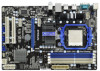
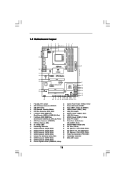
...30 Infrared Module Header (IR1) 11 Southbridge Controller 31 PCI Slots (PCI1-2) 12 SATA3 Connector (SATA5, White) 32 PCI Express x1 Slot (PCIE3; 1.3 Motherboard Layout 12 34 56 7 20.8cm (8.2-in) Support 6-Core CPU 1 PS2_USB_PW1 1 USB_LAN1 CPU_FAN1 ATX12V1 PS2 Mouse PS2 Keyboard AM3 HT 3.0 Dual Channel COM1... T: USB0 B: USB1 Top: RJ-45 Top: LINE IN Center: FRONT Bottom: MIC IN 35 34 LAN PHY PWR_FAN1 PCIE1 AMD 870 Chipset 870iCafe ErP/EuP Ready RoHS Designed in Taipei 33 32 Super I/O 31 30 AUDIO CODEC IR1 1 HD_AUDIO1 1 29 PCIE2 CMOS BATTERY PCIE3 PCI Express ...
...30 Infrared Module Header (IR1) 11 Southbridge Controller 31 PCI Slots (PCI1-2) 12 SATA3 Connector (SATA5, White) 32 PCI Express x1 Slot (PCIE3; 1.3 Motherboard Layout 12 34 56 7 20.8cm (8.2-in) Support 6-Core CPU 1 PS2_USB_PW1 1 USB_LAN1 CPU_FAN1 ATX12V1 PS2 Mouse PS2 Keyboard AM3 HT 3.0 Dual Channel COM1... T: USB0 B: USB1 Top: RJ-45 Top: LINE IN Center: FRONT Bottom: MIC IN 35 34 LAN PHY PWR_FAN1 PCIE1 AMD 870 Chipset 870iCafe ErP/EuP Ready RoHS Designed in Taipei 33 32 Super I/O 31 30 AUDIO CODEC IR1 1 HD_AUDIO1 1 29 PCIE2 CMOS BATTERY PCIE3 PCI Express ...

User Manual
Page 13
...not over-tighten the screws! Installation This is detached from the wall socket before you install motherboard components or change any component, place it . Pre-installation Precautions Take note of your motherboard directly on a grounded antistatic pad or in the bag that the power is switched off ...or the power cord is an ATX form factor (12.0-in x 8.2-in, 30.5 cm x 20.8 cm) motherboard. Failure to the motherboard, peripherals, and/or components. 1. Doing so may cause severe damage to do not touch the ICs. 4. Hold components by the edges ...
...not over-tighten the screws! Installation This is detached from the wall socket before you install motherboard components or change any component, place it . Pre-installation Precautions Take note of your motherboard directly on a grounded antistatic pad or in the bag that the power is switched off ...or the power cord is an ATX form factor (12.0-in x 8.2-in, 30.5 cm x 20.8 cm) motherboard. Failure to the motherboard, peripherals, and/or components. 1. Doing so may cause severe damage to do not touch the ICs. 4. Hold components by the edges ...
User Manual
Page 14
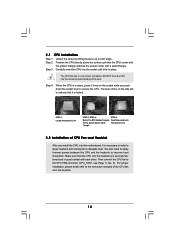
... place. When the CPU is in good contact with a small triangle. Step 4. The lever clicks on the socket while you install the CPU into this motherboard, it fits in one correct orientation. Lever 90° Up STEP 1: Lift Up The Socket Lever CPU Golden Triangle Socker Corner Small Triangle STEP 2 / STEP...
... place. When the CPU is in good contact with a small triangle. Step 4. The lever clicks on the socket while you install the CPU into this motherboard, it fits in one correct orientation. Lever 90° Up STEP 1: Lift Up The Socket Lever CPU Golden Triangle Socker Corner Small Triangle STEP 2 / STEP...

User Manual
Page 15
... pair of white slots (DDR3_A2 and DDR3_B2). 2. It is unable to install identical DDR3 DIMM pair in all four slots. 1. This motherboard also allows you have to activate the Dual Channel Memory Technology . 4. White slots; If a pair of memory modules is NOT installed ...and chiptype) DDR3 DIMM pair in DDR3_A1 and DDR3_A2, it is recommended to the Dual Channel Memory Configuration Table below. otherwise, this motherboard, it is unable to activate the Dual Channel Memory Technology. 3. 2.3 Installation of the same color. Dual Channel Memory Configurations DDR3_A1 DDR3_B1...
... pair of white slots (DDR3_A2 and DDR3_B2). 2. It is unable to install identical DDR3 DIMM pair in all four slots. 1. This motherboard also allows you have to activate the Dual Channel Memory Technology . 4. White slots; If a pair of memory modules is NOT installed ...and chiptype) DDR3 DIMM pair in DDR3_A1 and DDR3_A2, it is recommended to the Dual Channel Memory Configuration Table below. otherwise, this motherboard, it is unable to activate the Dual Channel Memory Technology. 3. 2.3 Installation of the same color. Dual Channel Memory Configurations DDR3_A1 DDR3_B1...

User Manual
Page 16
... 1. Step 3. Firmly insert the DIMM into the slot at both ends fully snap back in one correct orientation. Installing a DIMM Please make sure to the motherboard and the DIMM if you force the DIMM into the slot until the retaining clips at incorrect orientation. Step 2.
... 1. Step 3. Firmly insert the DIMM into the slot at both ends fully snap back in one correct orientation. Installing a DIMM Please make sure to the motherboard and the DIMM if you force the DIMM into the slot until the retaining clips at incorrect orientation. Step 2.

User Manual
Page 17
... Step 1. Step 4. Before installing the expansion card, please make necessary hardware settings for PCI Express cards with screws. Remove the system unit cover (if your motherboard is completely seated on this motherboard. Align the card connector with the slot and press firmly until the card is already installed in a chassis).
... Step 1. Step 4. Before installing the expansion card, please make necessary hardware settings for PCI Express cards with screws. Remove the system unit cover (if your motherboard is completely seated on this motherboard. Align the card connector with the slot and press firmly until the card is already installed in a chassis).

User Manual
Page 20
The current SATA 4 SATA 3 (SATA4: see p.11, No. 14) SATA3 interface allows up to the SATA3 hard disk or the SATA3 connector on this motherboard. Serial ATA (SATA) Data Cable (Optional) SATA2 USB 2.0 Headers (9-pin USB10_11) (see p.11 No. 27) (9-pin USB8_9) (see p.11 No....10 USB_PWR USB_PWR P-9 P+9 GND DUMMY 1 GND P+8 P-8 USB_PWR USB_PWR P-7 P+7 GND DUMMY 1 GND P+6 P-6 USB_PWR IRTX +5V DUMMY 1 GND IRRX Either end of the motherboard! • Serial ATA3 Connectors These six Serial ATA3 SATA6 SATA5 (SATA1: see p.11, No. 17) (SATA3) connectors support (SATA2: see p.11, No. 18) ...
The current SATA 4 SATA 3 (SATA4: see p.11, No. 14) SATA3 interface allows up to the SATA3 hard disk or the SATA3 connector on this motherboard. Serial ATA (SATA) Data Cable (Optional) SATA2 USB 2.0 Headers (9-pin USB10_11) (see p.11 No. 27) (9-pin USB8_9) (see p.11 No....10 USB_PWR USB_PWR P-9 P+9 GND DUMMY 1 GND P+8 P-8 USB_PWR USB_PWR P-7 P+7 GND DUMMY 1 GND P+6 P-6 USB_PWR IRTX +5V DUMMY 1 GND IRRX Either end of the motherboard! • Serial ATA3 Connectors These six Serial ATA3 SATA6 SATA5 (SATA1: see p.11, No. 17) (SATA3) connectors support (SATA2: see p.11, No. 18) ...

User Manual
Page 22
...) (see p.11 No. 5) FAN_SPEED_CONTROL 4 CPU_FAN_SPEED 3 +12V 2 GND 1 Please connect the CPU fan cable to this connector and match the black wire to this motherboard, please connect it to Pin 1-3. Chassis Speaker Header (4-pin SPEAKER 1) (see p.11 No. 19) Power LED Header (3-pin PLED1) (see p.11 No. 8) 12... off). The LED is operating. Though this connector. 1 13 22 If you plan to connect the 3-Pin CPU fan to this motherboard provides 4-Pin CPU fan (Quiet Fan) support, the 3-Pin CPU fan still can work successfully even without the fan speed control function.
...) (see p.11 No. 5) FAN_SPEED_CONTROL 4 CPU_FAN_SPEED 3 +12V 2 GND 1 Please connect the CPU fan cable to this connector and match the black wire to this motherboard, please connect it to Pin 1-3. Chassis Speaker Header (4-pin SPEAKER 1) (see p.11 No. 19) Power LED Header (3-pin PLED1) (see p.11 No. 8) 12... off). The LED is operating. Though this connector. 1 13 22 If you plan to connect the 3-Pin CPU fan to this motherboard provides 4-Pin CPU fan (Quiet Fan) support, the 3-Pin CPU fan still can work successfully even without the fan speed control function.

User Manual
Page 23
Though this motherboard provides 24-pin ATX power connector, 12 24 it can still work if you adopt a traditional 20-pin ATX power supply. Though this connector. To .... 20-Pin ATX Power Supply Installation 1 13 ATX 12V Power Connector 8 5 (8-pin ATX12V1) (see p.11 No. 2) 4 1 Please connect an ATX 12V power supply to this motherboard provides 8-pin ATX 12V power connector, it can still work if you adopt a traditional 4-pin ATX 12V power supply.
Though this motherboard provides 24-pin ATX power connector, 12 24 it can still work if you adopt a traditional 20-pin ATX power supply. Though this connector. To .... 20-Pin ATX Power Supply Installation 1 13 ATX 12V Power Connector 8 5 (8-pin ATX12V1) (see p.11 No. 2) 4 1 Please connect an ATX 12V power supply to this motherboard provides 8-pin ATX 12V power connector, it can still work if you adopt a traditional 4-pin ATX 12V power supply.

User Manual
Page 27
...However, please note that supports Serial ATA3 (SATA3) hard disks and RAID functions. STEP 3: Connect one end of the SATA data cable to the motherboard's SATA3 connector. You may install SATA3 hard disks on and in working condition. 27 STEP 2: Connect the SATA power cable to install the SATA3 ...This section will guide you to the SATA3 hard disk. If SATA3 HDDs are NOT set for RAID configuration, it is still power-on this motherboard for the action to insert and remove the SATA3 HDDs while the system is called "Hot Plug" for internal storage devices. STEP 1: Install ...
...However, please note that supports Serial ATA3 (SATA3) hard disks and RAID functions. STEP 3: Connect one end of the SATA data cable to the motherboard's SATA3 connector. You may install SATA3 hard disks on and in working condition. 27 STEP 2: Connect the SATA power cable to install the SATA3 ...This section will guide you to the SATA3 hard disk. If SATA3 HDDs are NOT set for RAID configuration, it is still power-on this motherboard for the action to insert and remove the SATA3 HDDs while the system is called "Hot Plug" for internal storage devices. STEP 1: Install ...
User Manual
Page 28
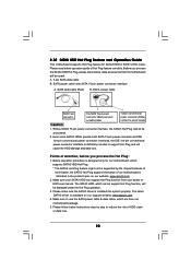
...on our support website: www.asrock.com 4. Please read below instructions step by the chipset because of its limitation, the SATA3 Hot Plug support information of attention, before you process the SATA3 HDD Hot Plug, please check below cable accessories from our motherboard package. 5. SATA power cable... connect to support Hot Plug and will be processed. 2. 2.10 SATA3 HDD Hot Plug Feature and Operation Guide This motherboard supports Hot Plug feature for our motherboard, which supports SATA3 HDD Hot Plug. * The SATA3 Hot Plug feature might not be supported by step to use the...
...on our support website: www.asrock.com 4. Please read below instructions step by the chipset because of its limitation, the SATA3 Hot Plug support information of attention, before you process the SATA3 HDD Hot Plug, please check below cable accessories from our motherboard package. 5. SATA power cable... connect to support Hot Plug and will be processed. 2. 2.10 SATA3 HDD Hot Plug Feature and Operation Guide This motherboard supports Hot Plug feature for our motherboard, which supports SATA3 HDD Hot Plug. * The SATA3 Hot Plug feature might not be supported by step to use the...

User Manual
Page 29
... Hot Plug: Please do follow below instruction sequence to process the Hot Unplug, improper procedure will cause the SATA3 HDD damage and data loss. the motherboard's SATA3 connector. SATA power cable 1x4-pin power connector (White) Step 3 Connect SATA 15-pin power cable connector (Black) end to the SATA3 HDD. Step...
... Hot Plug: Please do follow below instruction sequence to process the Hot Unplug, improper procedure will cause the SATA3 HDD damage and data loss. the motherboard's SATA3 connector. SATA power cable 1x4-pin power connector (White) Step 3 Connect SATA 15-pin power cable connector (Black) end to the SATA3 HDD. Step...
User Manual
Page 33
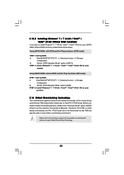
... Mode" option to [IDE]. Set the "SATA Operation Mode" option to [AHCI]. Please refer to the warning on your system. 2.14 Untied Overclocking Technology This motherboard supports Untied Overclocking Technology, which means during overclocking, but PCI / PCIE buses are in the fixed mode so that FSB can operate under a more stable...
... Mode" option to [IDE]. Set the "SATA Operation Mode" option to [AHCI]. Please refer to the warning on your system. 2.14 Untied Overclocking Technology This motherboard supports Untied Overclocking Technology, which means during overclocking, but PCI / PCIE buses are in the fixed mode so that FSB can operate under a more stable...

