
User Manual
Page 3
Installation 10 2.1 Screw Holes 10 2.2 Pre-installation Precautions 10 2.3 CPU Installation 11 2.4 Installation of CPU Fan and Heatsink 13 2.5 Installation of Memory Modules (DIMM 14 2.6 Expansion Slots (PCI, AMR, and AGP Slots 15 2.7 Jumpers Setup 16 2.8 Onboard Headers and Connectors 17 2.9 Serial ATA (SATA)... Configuration 29 3.3.5 PCIPnP Configuration 31 3.3.6 Floppy Configuration 31 3.3.7 Super IO Configuration 32 3.3.8 USB Configuration 33 3 Contents 1. Introduction 5 1.1 Package Contents 5 1.2 Specifications 6 1.3 Motherboard Layout 8 1.4 ASRock I/O Plus 9 TM 2.
Installation 10 2.1 Screw Holes 10 2.2 Pre-installation Precautions 10 2.3 CPU Installation 11 2.4 Installation of CPU Fan and Heatsink 13 2.5 Installation of Memory Modules (DIMM 14 2.6 Expansion Slots (PCI, AMR, and AGP Slots 15 2.7 Jumpers Setup 16 2.8 Onboard Headers and Connectors 17 2.9 Serial ATA (SATA)... Configuration 29 3.3.5 PCIPnP Configuration 31 3.3.6 Floppy Configuration 31 3.3.7 Super IO Configuration 32 3.3.8 USB Configuration 33 3 Contents 1. Introduction 5 1.1 Package Contents 5 1.2 Specifications 6 1.3 Motherboard Layout 8 1.4 ASRock I/O Plus 9 TM 2.
User Manual
Page 5
... Cable One Serial ATA (SATA) HDD Power Cable(Optional) One ASRock I/O PlusTM Shield One COM Port Bracket 5 Introduction Thank you for a 3.5-in , 24.4 cm x 20.8 cm) ASRock 775VM8 Quick Installation Guide ASRock 775VM8 Support CD (including LGA 775 CPU Installation Live Demo) One 80...purchasing ASRock 775VM8 motherboard, a reliable motherboard produced under ASRock's consistently stringent quality control. In case any modifications of this manual occur, the updated version will be available on ASRock website as well. You may find the latest memory and CPU support lists on ASRock website...
... Cable One Serial ATA (SATA) HDD Power Cable(Optional) One ASRock I/O PlusTM Shield One COM Port Bracket 5 Introduction Thank you for a 3.5-in , 24.4 cm x 20.8 cm) ASRock 775VM8 Quick Installation Guide ASRock 775VM8 Support CD (including LGA 775 CPU Installation Live Demo) One 80...purchasing ASRock 775VM8 motherboard, a reliable motherboard produced under ASRock's consistently stringent quality control. In case any modifications of this manual occur, the updated version will be available on ASRock website as well. You may find the latest memory and CPU support lists on ASRock website...

User Manual
Page 6
... 800/533 MHz, with Intel® Hyper-Threading Technology ready (see CAUTION 1) South Bridge: VIA VT8237R, supports USB 2.0, ATA 133, SATA 1.5Gb/s Memory: 2 DDR DIMM Slots: DDR1 and DDR2 1 DDR DIMM Slot Supports PC3200 (DDR400), Max. 1GB, 2 DDR DIMM Slots Supports PC2700 (DDR333) / ...3u (10/100 Ethernet), supports Wake-On-LAN Hardware Monitor: CPU temperature sensing Chassis temperature sensing CPU overheat shutdown to protect CPU life (ASRock U-COP)(see CAUTION 2) CPU fan tachometer Chassis fan tachometer Voltage monitoring: +12V, +5V, +3.3V, Vcore PCI slots: 3 slots with...
... 800/533 MHz, with Intel® Hyper-Threading Technology ready (see CAUTION 1) South Bridge: VIA VT8237R, supports USB 2.0, ATA 133, SATA 1.5Gb/s Memory: 2 DDR DIMM Slots: DDR1 and DDR2 1 DDR DIMM Slot Supports PC3200 (DDR400), Max. 1GB, 2 DDR DIMM Slots Supports PC2700 (DDR333) / ...3u (10/100 Ethernet), supports Wake-On-LAN Hardware Monitor: CPU temperature sensing Chassis temperature sensing CPU overheat shutdown to protect CPU life (ASRock U-COP)(see CAUTION 2) CPU fan tachometer Chassis fan tachometer Voltage monitoring: +12V, +5V, +3.3V, Vcore PCI slots: 3 slots with...
User Manual
Page 8
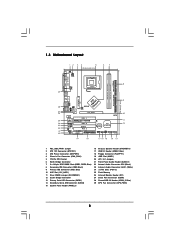
...Header (AUDIO1) 22 Internal Audio Connector: CD1 (Black) 23 Internal Audio Connector: AUX1 (White) 24 3 x PCI Slots (PCI1- 3) 25 Flash Memory 26 Infrared Module Header (IR1) 27 Serial Port Connector (COM1) 28 Shared USB 2.0 Header (USB4_5, Blue) 29 CPU Fan Connector (CPU_FAN1) 8 1.3...B: USB5 1 IR1 USB4_5 ATXPWR1 AGP 8X VPIMACh80ip0set IDE2 Super I/O LAN PHY 4Mb BIOS AUX1 CD1 Audio CODEC 1 AUDIO1 JR1 JL1 1.5V_AGP1 PCI 1 ` 775VM8 PCI 2 USB2.0 PCI 3 5.1CH FLOPPY1 AMR1 CLRCMOS1 CMOS Battery VIA VT8237R 1 USB67 PANEL 1 PLED PWRBTN 1 1 SPEAKER1 HDLED RESET SATA2 IDE1 SATA SATA1...
...Header (AUDIO1) 22 Internal Audio Connector: CD1 (Black) 23 Internal Audio Connector: AUX1 (White) 24 3 x PCI Slots (PCI1- 3) 25 Flash Memory 26 Infrared Module Header (IR1) 27 Serial Port Connector (COM1) 28 Shared USB 2.0 Header (USB4_5, Blue) 29 CPU Fan Connector (CPU_FAN1) 8 1.3...B: USB5 1 IR1 USB4_5 ATXPWR1 AGP 8X VPIMACh80ip0set IDE2 Super I/O LAN PHY 4Mb BIOS AUX1 CD1 Audio CODEC 1 AUDIO1 JR1 JL1 1.5V_AGP1 PCI 1 ` 775VM8 PCI 2 USB2.0 PCI 3 5.1CH FLOPPY1 AMR1 CLRCMOS1 CMOS Battery VIA VT8237R 1 USB67 PANEL 1 PLED PWRBTN 1 1 SPEAKER1 HDLED RESET SATA2 IDE1 SATA SATA1...
User Manual
Page 14
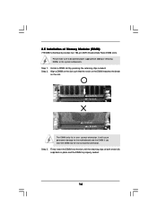
... properly seated. 14 Step 1. Align a DIMM on the slot such that the notch on the DIMM matches the break on the slot. 2.5 Installation of Memory Modules (DIMM) 775VM8 motherboard provides two 184-pin DDR (Double Data Rate) DIMM slots. Unlock a DIMM slot by pressing the retaining clips outward. Firmly insert the DIMM...
... properly seated. 14 Step 1. Align a DIMM on the slot such that the notch on the DIMM matches the break on the slot. 2.5 Installation of Memory Modules (DIMM) 775VM8 motherboard provides two 184-pin DDR (Double Data Rate) DIMM slots. Unlock a DIMM slot by pressing the retaining clips outward. Firmly insert the DIMM...
User Manual
Page 23
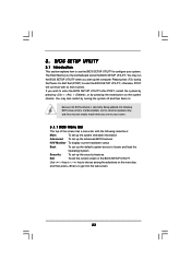
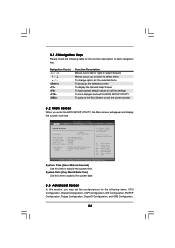
..., otherwise, POST will continue with its test routines. You may not exactly match what you wish to get into the sub screen. 23 The Flash Memory on the system chassis. Because the BIOS software is constantly being updated, the following BIOS setup screens and descriptions are for reference purpose only, and...
..., otherwise, POST will continue with its test routines. You may not exactly match what you wish to get into the sub screen. 23 The Flash Memory on the system chassis. Because the BIOS software is constantly being updated, the following BIOS setup screens and descriptions are for reference purpose only, and...
User Manual
Page 24
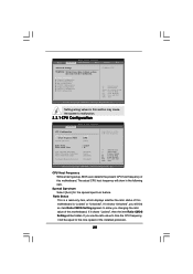
...UTILITY Main Advanced H/W Monitor Boot Security Exit System Overview System Time System Date [17:00:09] [Thu 04/28/2005] BIOS Version : 775VM8 BIOS P1.00 Processor Type : Intel (R) CPU 3.20 GHz Processor Speed : 3200 MHz Cache Size : 1024KB Microcode Update : 0F34/0E Total... Memory DIMM 1 DIMM 2 : 256MB with 64MB shared memory : 256MB/166MHz (DDR333) : None Use [Enter], [TAB] or [SHIFT-TAB] to configure system Time. +Tab F1 F9 F10 ESC Select ...
...UTILITY Main Advanced H/W Monitor Boot Security Exit System Overview System Time System Date [17:00:09] [Thu 04/28/2005] BIOS Version : 775VM8 BIOS P1.00 Processor Type : Intel (R) CPU 3.20 GHz Processor Speed : 3200 MHz Cache Size : 1024KB Microcode Update : 0F34/0E Total... Memory DIMM 1 DIMM 2 : 256MB with 64MB shared memory : 256MB/166MHz (DDR333) : None Use [Enter], [TAB] or [SHIFT-TAB] to configure system Time. +Tab F1 F9 F10 ESC Select ...
User Manual
Page 25
... CPU Host Frequency Actual Frequency (MHz) Spread Spectrum Ratio Status Ratio Actual Value CPU Thermal Throttling Hyper Threading Technology Max CPUID Value Limit No-Excute Memory Protection [Auto] [200] [Auto] : Locked : 16 [Enabled] [Auto] [Disabled] [Disabled] Select how to malfunction. Setting wrong values in this motherboard is "Locked" or "Unlocked". CPU...
... CPU Host Frequency Actual Frequency (MHz) Spread Spectrum Ratio Status Ratio Actual Value CPU Thermal Throttling Hyper Threading Technology Max CPUID Value Limit No-Excute Memory Protection [Auto] [200] [Auto] : Locked : 16 [Enabled] [Auto] [Disabled] [Disabled] Select how to malfunction. Setting wrong values in this motherboard is "Locked" or "Unlocked". CPU...
User Manual
Page 26
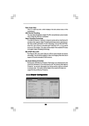
...Intel Pentium®4 processor that supports Hyper-Threading technology and an operating system that cannot support CPUs with "No Execute (NX) Memory Protection" can prevent data pages from being used by malicious software to keep the CPU from overheated. CPU Thermal Throttling You .... Hyper Threading Technology To enable this motherboard. This option will be hidden if the current CPU does not support No-Excute Memory Protection. 3.3.2 Chipset Configuration BIOS SETUP UTILITY Advanced Chipset Configuration DRAM Frequency Flexibility Option DRAM CAS# Latency DRAM Command Rate DRAM ...
...Intel Pentium®4 processor that supports Hyper-Threading technology and an operating system that cannot support CPUs with "No Execute (NX) Memory Protection" can prevent data pages from being used by malicious software to keep the CPU from overheated. CPU Thermal Throttling You .... Hyper Threading Technology To enable this motherboard. This option will be hidden if the current CPU does not support No-Excute Memory Protection. 3.3.2 Chipset Configuration BIOS SETUP UTILITY Advanced Chipset Configuration DRAM Frequency Flexibility Option DRAM CAS# Latency DRAM Command Rate DRAM ...
User Manual
Page 27
...Disabled]. AGP Fast Write This allows you may set to [Enabled]. The default value of this option is set the share memory size to a section of memory accessing. DRAM CAS# Latency Use this item to select among [Normal] and [High] for AGP Voltage. AGP Voltage Use...[166MHz (DDR 333)], [200MHz (DDR 400)]. Configuration options: [Auto], [2.5], [2], and [3]. DRAM Voltage Use this to adjust the means of the PCI memory address range used for DRAM Command Rate. Primary Graphics Adapter This allows you may select [Auto], [8X] or [4X] as the primary graphics adapter. ...
...Disabled]. AGP Fast Write This allows you may set to [Enabled]. The default value of this option is set the share memory size to a section of memory accessing. DRAM CAS# Latency Use this item to select among [Normal] and [High] for AGP Voltage. AGP Voltage Use...[166MHz (DDR 333)], [200MHz (DDR 400)]. Configuration options: [Auto], [2.5], [2], and [3]. DRAM Voltage Use this to adjust the means of the PCI memory address range used for DRAM Command Rate. Primary Graphics Adapter This allows you may select [Auto], [8X] or [4X] as the primary graphics adapter. ...

