User Manual
Page 11
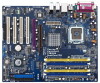
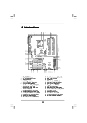
...Module Header (IR1) 28 Internal Audio Connector: CD1 (Black) 29 ATX Power Connector (ATXPWR1) 11 1.5 Motherboard Layout 1 2 3 45 24.4cm (9.6 in) 1 PS2 Mouse PS2_USB_PWR1 ATX12V1 PS2 Keyboard CPU_FAN1 67 ... AGP 8X 1.5V_AGP1 PCI EXPRESS PCIE_GRAPHICS1 Quad Core CPU RAID IDE1 IDE2 ATA133 PCI 1 LAN PHY 4CoreDual-VSTA 1 HD_AUDIO1 PCI 2 USB2.0 PCI 3 CMOS Battery CLRCMOS1 Audio CODEC HDMI_SPDIF1 GAME1 1 1 PCI...ATX 12V Connector (ATX12V1) 3 775-Pin CPU Socket 4 North Bridge Controller 5 CPU Fan Connector (CPU_FAN1) 6 2 x 240-pin DDRII DIMM Slots (Dual Channel A:...
...Module Header (IR1) 28 Internal Audio Connector: CD1 (Black) 29 ATX Power Connector (ATXPWR1) 11 1.5 Motherboard Layout 1 2 3 45 24.4cm (9.6 in) 1 PS2 Mouse PS2_USB_PWR1 ATX12V1 PS2 Keyboard CPU_FAN1 67 ... AGP 8X 1.5V_AGP1 PCI EXPRESS PCIE_GRAPHICS1 Quad Core CPU RAID IDE1 IDE2 ATA133 PCI 1 LAN PHY 4CoreDual-VSTA 1 HD_AUDIO1 PCI 2 USB2.0 PCI 3 CMOS Battery CLRCMOS1 Audio CODEC HDMI_SPDIF1 GAME1 1 1 PCI...ATX 12V Connector (ATX12V1) 3 775-Pin CPU Socket 4 North Bridge Controller 5 CPU Fan Connector (CPU_FAN1) 6 2 x 240-pin DDRII DIMM Slots (Dual Channel A:...

User Manual
Page 13
...4CoreDual-VSTA is detached from the wall socket before you install the motherboard, study the configuration of the following precautions before installing or removing the motherboard. To avoid damaging the motherboard components due to static electricity, NEVER place your chassis to use a grounded wrist strap or touch a safety grounded object before touching any motherboard... power cord is an ATX form factor (12.0" x 9.6", 30.5 x 24.4 cm) motherboard. Make sure to the motherboard, peripherals, and/or components. 13 Failure to do so may cause physical injuries to you ...
...4CoreDual-VSTA is detached from the wall socket before you install the motherboard, study the configuration of the following precautions before installing or removing the motherboard. To avoid damaging the motherboard components due to static electricity, NEVER place your chassis to use a grounded wrist strap or touch a safety grounded object before touching any motherboard... power cord is an ATX form factor (12.0" x 9.6", 30.5 x 24.4 cm) motherboard. Make sure to the motherboard, peripherals, and/or components. 13 Failure to do so may cause physical injuries to you ...

User Manual
Page 15
... of the CPU with right hand thumb and peel the cap from the socket while pressing on load plate, engage the load lever. This cap must be placed if returning the motherboard for after service. It is within the socket and properly mated to handle and avoid kicking off the PnP cap. 2. ...Close the socket: Step 4-1. Verify that the CPU is recommended to use the cap tab to the...
... of the CPU with right hand thumb and peel the cap from the socket while pressing on load plate, engage the load lever. This cap must be placed if returning the motherboard for after service. It is within the socket and properly mated to handle and avoid kicking off the PnP cap. 2. ...Close the socket: Step 4-1. Verify that the CPU is recommended to use the cap tab to the...

User Manual
Page 16
... and lock. Then connect the CPU fan to the CPU fan connector on the socket surface. Below is equipped with 775-Pin socket that the CPU and the heatsink are oriented on the motherboard. Step 4. Ensure fan cables are securely fastened and in good contact with thumb ... heatsink. Step 1. Step 6. Ensure that supports Intel 775-LAND CPU. Step 2. Place the heatsink onto the socket. Before you installed the heatsink, you press down on the motherboard. Connect fan header with fan operation or contact other . Apply thermal interface material onto center of the heatsink for...
... and lock. Then connect the CPU fan to the CPU fan connector on the socket surface. Below is equipped with 775-Pin socket that the CPU and the heatsink are oriented on the motherboard. Step 4. Ensure fan cables are securely fastened and in good contact with thumb ... heatsink. Step 1. Step 6. Ensure that supports Intel 775-LAND CPU. Step 2. Place the heatsink onto the socket. Before you installed the heatsink, you press down on the motherboard. Connect fan header with fan operation or contact other . Apply thermal interface material onto center of the heatsink for...

Quick Installation Guide
Page 2
... Slots (PCI1- 4) 26 PCI Express Graphics Slot 27 Infrared Module Header (IR1) 28 Internal Audio Connector: CD1 (Black) 29 ATX Power Connector (ATXPWR1) 2 ASRock 4CoreDual-VSTA Motherboard Motherboard Layout English 1 PS2_USB_PWR1 Jumper 2 ATX 12V Connector (ATX12V1) 3 775-Pin CPU Socket 4 North Bridge Controller 5 CPU Fan Connector (CPU_FAN1) 6 2 x 240-pin DDRII DIMM Slots (Dual Channel A: DDRII_1, DDRII_2;
... Slots (PCI1- 4) 26 PCI Express Graphics Slot 27 Infrared Module Header (IR1) 28 Internal Audio Connector: CD1 (Black) 29 ATX Power Connector (ATXPWR1) 2 ASRock 4CoreDual-VSTA Motherboard Motherboard Layout English 1 PS2_USB_PWR1 Jumper 2 ATX 12V Connector (ATX12V1) 3 775-Pin CPU Socket 4 North Bridge Controller 5 CPU Fan Connector (CPU_FAN1) 6 2 x 240-pin DDRII DIMM Slots (Dual Channel A: DDRII_1, DDRII_2;

Quick Installation Guide
Page 10
... CPU surface is unclean or if there is found. When placing screws into the socket if above situation is any motherboard settings. 1. Do not force to the motherboard, peripherals, and/or components. 2. Otherwise, the CPU will be seriously damaged. 10 ASRock 4CoreDual-VSTA Motherboard English Installation Pre-installation Precautions Take note of Intel 775-LAND CPU, please...
... CPU surface is unclean or if there is found. When placing screws into the socket if above situation is any motherboard settings. 1. Do not force to the motherboard, peripherals, and/or components. 2. Otherwise, the CPU will be seriously damaged. 10 ASRock 4CoreDual-VSTA Motherboard English Installation Pre-installation Precautions Take note of Intel 775-LAND CPU, please...

Quick Installation Guide
Page 11
...Insert the 775-LAND CPU: Step 2-1. Pin1 orientation key notch orientation key notch Pin1 alignment key alignment key 775-LAND CPU 775-Pin Socket For proper inserting, please ensure to clear retention tab. Orient the CPU with black lines. Remove PnP Cap (Pick and Place Cap...the socket: Step 1-1. black line black line Step 2-2. Carefully place the CPU into the socket by the edges where are marked with IHS (Integrated Heat Sink) up. Step 1. Step 1-3. Verify that the CPU is within the socket and properly mated to assist in removal. 11 ASRock 4CoreDual-VSTA Motherboard ...
...Insert the 775-LAND CPU: Step 2-1. Pin1 orientation key notch orientation key notch Pin1 alignment key alignment key 775-LAND CPU 775-Pin Socket For proper inserting, please ensure to clear retention tab. Orient the CPU with black lines. Remove PnP Cap (Pick and Place Cap...the socket: Step 1-1. black line black line Step 2-2. Carefully place the CPU into the socket by the edges where are marked with IHS (Integrated Heat Sink) up. Step 1. Step 1-3. Verify that the CPU is within the socket and properly mated to assist in removal. 11 ASRock 4CoreDual-VSTA Motherboard ...

Quick Installation Guide
Page 12
... lightly on fastener caps with the CPU fan connector on the motherboard (CPU_FAN1, see page 2, No. 5). Repeat with fan operation or contact other components. 12 ASRock 4CoreDual-VSTA Motherboard Secure excess cable with tie-wrap to the CPU fan connector on the motherboard. Close the socket: Step 4-1. Step 4-3. Apply thermal interface material onto center of your CPU...
... lightly on fastener caps with the CPU fan connector on the motherboard (CPU_FAN1, see page 2, No. 5). Repeat with fan operation or contact other components. 12 ASRock 4CoreDual-VSTA Motherboard Secure excess cable with tie-wrap to the CPU fan connector on the motherboard. Close the socket: Step 4-1. Step 4-3. Apply thermal interface material onto center of your CPU...


