
User Manual
Page 13
...the load plate to fully open position at approximately 100 degrees. Pin1 orientation key notch orientation key notch Pin1 alignment key alignment key 775-LAND CPU 775-Pin Socket 13 black line black line Step 1. Rotate the load lever to fully open position at approximately 135 degrees. Step 2. Step ... Hold the CPU by depressing down and out on the socket. 2.3 CPU Installation For the installation of Intel 775-LAND CPU, please follow the steps below. 775-Pin Socket Overview Before you insert the 775-LAND CPU into the socket if above situation is any bent pin on the hook ...
...the load plate to fully open position at approximately 100 degrees. Pin1 orientation key notch orientation key notch Pin1 alignment key alignment key 775-LAND CPU 775-Pin Socket 13 black line black line Step 1. Rotate the load lever to fully open position at approximately 135 degrees. Step 2. Step ... Hold the CPU by depressing down and out on the socket. 2.3 CPU Installation For the installation of Intel 775-LAND CPU, please follow the steps below. 775-Pin Socket Overview Before you insert the 775-LAND CPU into the socket if above situation is any bent pin on the hook ...

User Manual
Page 15
... and Heatsink This motherboard is an example to dissipate heat. Step 2. Place the heatsink onto the socket. Step 6. 2.4 Installation of the heatsink for 775-LAND CPU. Ensure that supports Intel 775-LAND CPU. Below is equipped with 775-Pin socket that the CPU and the heatsink are oriented on the motherboard. Step 4. Rotate the fastener...
... and Heatsink This motherboard is an example to dissipate heat. Step 2. Place the heatsink onto the socket. Step 6. 2.4 Installation of the heatsink for 775-LAND CPU. Ensure that supports Intel 775-LAND CPU. Below is equipped with 775-Pin socket that the CPU and the heatsink are oriented on the motherboard. Step 4. Rotate the fastener...

Quick Installation Guide
Page 2
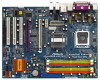
Motherboard Layout English 1 PS2_USB_PWR1 Jumper 2 ATX 12V Connector (ATX12V1) 3 FSB1 / FSB2 Jumpers 4 775-Pin CPU Socket 5 CPU Fan Connector (CPU_FAN1) 6 2 x 240-pin DDRII DIMM Slots (Dual Channel A: DDRII_1, DDRII_3; Yellow) 7 2 x 240-pin DDRII DIMM Slots (Dual Channel B: DDRII_2, DDRII_4; Orange) 8 IDE1 ... (PCIE2) 32 North Bridge Controller 33 PCI Express x1 Slot (PCIE1) 34 SLI / XFIRE Power Connector 35 ATX Power Connector (ATXPWR1) 36 eSATAII Connector (eSATAII) 2 ASRock 4Core1333-eSATA2 Motherboard
Motherboard Layout English 1 PS2_USB_PWR1 Jumper 2 ATX 12V Connector (ATX12V1) 3 FSB1 / FSB2 Jumpers 4 775-Pin CPU Socket 5 CPU Fan Connector (CPU_FAN1) 6 2 x 240-pin DDRII DIMM Slots (Dual Channel A: DDRII_1, DDRII_3; Yellow) 7 2 x 240-pin DDRII DIMM Slots (Dual Channel B: DDRII_2, DDRII_4; Orange) 8 IDE1 ... (PCIE2) 32 North Bridge Controller 33 PCI Express x1 Slot (PCIE1) 34 SLI / XFIRE Power Connector 35 ATX Power Connector (ATXPWR1) 36 eSATAII Connector (eSATAII) 2 ASRock 4Core1333-eSATA2 Motherboard

Quick Installation Guide
Page 9
Whenever you handle components. 3. Otherwise, the CPU will be seriously damaged. 9 ASRock 4Core1333-eSATA2 Motherboard English Failure to do not touch the ICs. 4. Unplug the power cord from the wall socket before touching any motherboard settings. 1. Hold components by the edges and do so may damage the motherboard. ...holes to secure the motherboard to use a grounded wrist strap or touch a safety grounded object before you insert the 775-LAND CPU into the socket, please check if the CPU surface is unclean or if there is found. To avoid damaging the motherboard components ...
Whenever you handle components. 3. Otherwise, the CPU will be seriously damaged. 9 ASRock 4Core1333-eSATA2 Motherboard English Failure to do not touch the ICs. 4. Unplug the power cord from the wall socket before touching any motherboard settings. 1. Hold components by the edges and do so may damage the motherboard. ...holes to secure the motherboard to use a grounded wrist strap or touch a safety grounded object before you insert the 775-LAND CPU into the socket, please check if the CPU surface is unclean or if there is found. To avoid damaging the motherboard components ...

Quick Installation Guide
Page 10
... the CPU by using a purely vertical motion. Pin1 orientation key notch orientation key notch Pin1 alignment key alignment key 775-LAND CPU 775-Pin Socket For proper inserting, please ensure to fully open position at approximately 135 degrees. Step 2-4. Rotate the load lever to... at approximately 100 degrees. Step 2-3. Verify that the CPU is within the socket and properly mated to assist in removal. 10 ASRock 4Core1333-eSATA2 Motherboard Step 3. Step 1-2. Carefully place the CPU into the socket by the edges where are marked with IHS (Integrated Heat Sink) up....
... the CPU by using a purely vertical motion. Pin1 orientation key notch orientation key notch Pin1 alignment key alignment key 775-LAND CPU 775-Pin Socket For proper inserting, please ensure to fully open position at approximately 135 degrees. Step 2-4. Rotate the load lever to... at approximately 100 degrees. Step 2-3. Verify that the CPU is within the socket and properly mated to assist in removal. 10 ASRock 4Core1333-eSATA2 Motherboard Step 3. Step 1-2. Carefully place the CPU into the socket by the edges where are marked with IHS (Integrated Heat Sink) up....

Quick Installation Guide
Page 11
... see page 2, No. 5). Apply thermal interface material onto center of your CPU fan and heatsink. Place the heatsink onto the socket. Align fasteners with remaining fasteners. While pressing down lightly on the motherboard. Step 4-2. Repeat with the motherboard throughholes. 1. It ...be placed if returning the motherboard for 775-LAND CPU. If you press down on side closest to the instruction manuals of IHS on the motherboard. Step 5. Step 6. Secure excess cable with fan operation or contact other components. 11 ASRock 4Core1333-eSATA2 Motherboard English
... see page 2, No. 5). Apply thermal interface material onto center of your CPU fan and heatsink. Place the heatsink onto the socket. Align fasteners with remaining fasteners. While pressing down lightly on the motherboard. Step 4-2. Repeat with the motherboard throughholes. 1. It ...be placed if returning the motherboard for 775-LAND CPU. If you press down on side closest to the instruction manuals of IHS on the motherboard. Step 5. Step 6. Secure excess cable with fan operation or contact other components. 11 ASRock 4Core1333-eSATA2 Motherboard English