User Manual
Page 4
... 40 3.1 Introduction 40 3.1.1 BIOS Menu Bar 40 3.1.2 Navigation Keys 41 3.2 Main Screen 41 3.3 Advanced Screen 41 3.3.1 CPU Configuration 42 3.3.2 Chipset Configuration 44 3.3.3 ACPI Configuration 46 3.3.4 IDE Configuration 47 3.3.5 PCIPnP ...
... 40 3.1 Introduction 40 3.1.1 BIOS Menu Bar 40 3.1.2 Navigation Keys 41 3.2 Main Screen 41 3.3 Advanced Screen 41 3.3.1 CPU Configuration 42 3.3.2 Chipset Configuration 44 3.3.3 ACPI Configuration 46 3.3.4 IDE Configuration 47 3.3.5 PCIPnP ...
User Manual
Page 5
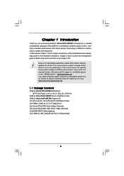
...introduction of the motherboard and step-bystep guide to BIOS setup and information of the Support CD. Because the motherboard specifications and the BIOS software might be updated, the content of this ...asrock.com/support/index.asp 1.1 Package Contents ASRock 4Core1333-eSATA2 Motherboard (ATX Form Factor: 12.0-in x 9.0-in, 30.5 cm x 22.9 cm) ASRock 4Core1333-eSATA2 Quick Installation Guide ASRock 4Core1333-eSATA2 Support CD One 80-conductor Ultra ATA 66/100 IDE Ribbon Cable One Ribbon Cable for purchasing ASRock 4Core1333-eSATA2 motherboard, a reliable motherboard produced under ASRock...
...introduction of the motherboard and step-bystep guide to BIOS setup and information of the Support CD. Because the motherboard specifications and the BIOS software might be updated, the content of this ...asrock.com/support/index.asp 1.1 Package Contents ASRock 4Core1333-eSATA2 Motherboard (ATX Form Factor: 12.0-in x 9.0-in, 30.5 cm x 22.9 cm) ASRock 4Core1333-eSATA2 Quick Installation Guide ASRock 4Core1333-eSATA2 Support CD One 80-conductor Ultra ATA 66/100 IDE Ribbon Cable One Ribbon Cable for purchasing ASRock 4Core1333-eSATA2 motherboard, a reliable motherboard produced under ASRock...

User Manual
Page 7
... Intel Matrix Storage), NCQ and AHCI functions (see CAUTION 10) - 1 x eSATAII 3.0Gb/s connector (shared with 1 SATAII port) (see CAUTION 13) - 4Mb AMI BIOS - Front panel audio connector - 1 x USB 2.0 header (supports 2 USB 2.0 ports) (see CAUTION 12) - 1 x WiFi header (see CAUTION 11) - 1...HDMI_SPDIF header - 1 x IEEE 1394 header - CPU/Chassis FAN connector - 24 pin ATX power connector - 4 pin 12V power connector - AMI Legal BIOS - Chassis Temperature Sensing - FCC, CE, WHQL 7 SLI/XFIRE power connector - Supports jumperfree - CD in header - Drivers, Utilities, AntiVirus Software (Trial...
... Intel Matrix Storage), NCQ and AHCI functions (see CAUTION 10) - 1 x eSATAII 3.0Gb/s connector (shared with 1 SATAII port) (see CAUTION 13) - 4Mb AMI BIOS - Front panel audio connector - 1 x USB 2.0 header (supports 2 USB 2.0 ports) (see CAUTION 12) - 1 x WiFi header (see CAUTION 11) - 1...HDMI_SPDIF header - 1 x IEEE 1394 header - CPU/Chassis FAN connector - 24 pin ATX power connector - 4 pin 12V power connector - AMI Legal BIOS - Chassis Temperature Sensing - FCC, CE, WHQL 7 SLI/XFIRE power connector - Supports jumperfree - CD in header - Drivers, Utilities, AntiVirus Software (Trial...
User Manual
Page 8
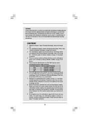
.... 2. CAUTION! 1. CPU FSB Frequency Memory Support Frequency 1333 DDRII667, DDRII800 1066 DDRII667, DDRII800 800 DDRII667, DDRII800 6. bit with overclocking, including adjusting the setting in the BIOS, applying Untied Overclocking Technology, or using the thirdparty overclocking tools. Although this motherboard, please read "Installation of your own risk and expense. mended to read...
.... 2. CAUTION! 1. CPU FSB Frequency Memory Support Frequency 1333 DDRII667, DDRII800 1066 DDRII667, DDRII800 800 DDRII667, DDRII800 6. bit with overclocking, including adjusting the setting in the BIOS, applying Untied Overclocking Technology, or using the thirdparty overclocking tools. Although this motherboard, please read "Installation of your own risk and expense. mended to read...

User Manual
Page 26
...Enter Advanced Settings, and then select Chipset Configuration. Front Panel Audio Header (9-pin HD_AUDIO1) GND PRESENCE# MIC_RET OUT_RET This is an interface for ASRock DeskExpress. D. System Panel Header (9-pin PANEL1) (see p.10 No. 25) 1 OUT2_L J_SENSE OUT2_R MIC2_R MIC2_L convenient connection and control of.... B. MIC_RET and OUT_RET are for AC'97 audio panel. Connect Audio_R (RIN) to OUT2_R and Audio_L (LIN) to Ground (GND). Enter BIOS Setup Utility. For Windows® 2000 / XP / XP 64-bit OS: Click "Audio I/O", select "Connector Settings" , choose "Disable front...
...Enter Advanced Settings, and then select Chipset Configuration. Front Panel Audio Header (9-pin HD_AUDIO1) GND PRESENCE# MIC_RET OUT_RET This is an interface for ASRock DeskExpress. D. System Panel Header (9-pin PANEL1) (see p.10 No. 25) 1 OUT2_L J_SENSE OUT2_R MIC2_R MIC2_L convenient connection and control of.... B. MIC_RET and OUT_RET are for AC'97 audio panel. Connect Audio_R (RIN) to OUT2_R and Audio_L (LIN) to Ground (GND). Enter BIOS Setup Utility. For Windows® 2000 / XP / XP 64-bit OS: Click "Audio I/O", select "Connector Settings" , choose "Disable front...

User Manual
Page 34
... message on the screen, "Do you want to install Windows® 2000 / XP / XP 64-bit on the support CD driver page. Enter BIOS SETUP UTILITY Advanced screen IDE Configuration. A. Please follow below steps. A. Then you see these messages, Please insert a diskette into the floppy diskette. ...34 Formatting the floppy diskette will lose ALL data in the option "Configure SATA as the boot device. STEP 1: Set up BIOS. B. Set "ATA/IDE Configuration" to format the floppy diskette and copy SATA / SATAII drivers into the floppy drive. Please insert a floppy ...
... message on the screen, "Do you want to install Windows® 2000 / XP / XP 64-bit on the support CD driver page. Enter BIOS SETUP UTILITY Advanced screen IDE Configuration. A. Please follow below steps. A. Then you see these messages, Please insert a diskette into the floppy diskette. ...34 Formatting the floppy diskette will lose ALL data in the option "Configure SATA as the boot device. STEP 1: Set up BIOS. B. Set "ATA/IDE Configuration" to format the floppy diskette and copy SATA / SATAII drivers into the floppy drive. Please insert a floppy ...

User Manual
Page 35
... hard disk. At the beginning of Windows setup, press F6 to install a third-party RAID driver. STEP 3: Use "RAID Installation Guide" to set up system BIOS as step 2 of page 34. After making a SATA / SATAII driver diskette and using RAID migration feature of Intel Matrix Storage. A "RAID Ready" system can start...
... hard disk. At the beginning of Windows setup, press F6 to install a third-party RAID driver. STEP 3: Use "RAID Installation Guide" to set up system BIOS as step 2 of page 34. After making a SATA / SATAII driver diskette and using RAID migration feature of Intel Matrix Storage. A "RAID Ready" system can start...
User Manual
Page 37
...® RAID drivers. STEP 2: Use "RAID Installation Guide" to set the option to [RAID]. page, please insert the ASRock Support CD into your system. Enter BIOS SETUP UTILITY Advanced screen IDE Configuration. Before you start to configure the RAID function, you need to create RAID array one by... Guide and the document in the support CD, "Guide to Intel Matrix Storage Manager", which is located in the folder at the same time under BIOS environment. A. When you see "Where do not create RAID 0 and RAID 5 or RAID 1 and RAID 5 at the following path: .. \ Intel Matrix ...
...® RAID drivers. STEP 2: Use "RAID Installation Guide" to set the option to [RAID]. page, please insert the ASRock Support CD into your system. Enter BIOS SETUP UTILITY Advanced screen IDE Configuration. Before you start to configure the RAID function, you need to create RAID array one by... Guide and the document in the support CD, "Guide to Intel Matrix Storage Manager", which is located in the folder at the same time under BIOS environment. A. When you see "Where do not create RAID 0 and RAID 5 or RAID 1 and RAID 5 at the following path: .. \ Intel Matrix ...
User Manual
Page 38
... IDE Configuration. Set "ATA/IDE Configuration" to [Enhanced], and then in the option "Configure SATA as ", please set the option to [IDE]. Enter BIOS SETUP UTILITY Advanced screen IDE Configuration. B. STEP 2: Install Windows® 2000 / XP / XP 64-bit OS on your system. Please make a SATA...Windows® 2000 / XP / XP 64-bit / VistaTM / VistaTM 64-bit OS on your SATA / SATAII HDDs without NCQ function STEP 1: Set up BIOS. When prompted, insert the SATA / SATAII driver diskette containing the Intel® AHCI driver. A. 2.17 Installing Windows® 2000 / XP / XP 64-bit...
... IDE Configuration. Set "ATA/IDE Configuration" to [Enhanced], and then in the option "Configure SATA as ", please set the option to [IDE]. Enter BIOS SETUP UTILITY Advanced screen IDE Configuration. B. STEP 2: Install Windows® 2000 / XP / XP 64-bit OS on your system. Please make a SATA...Windows® 2000 / XP / XP 64-bit / VistaTM / VistaTM 64-bit OS on your SATA / SATAII HDDs without NCQ function STEP 1: Set up BIOS. When prompted, insert the SATA / SATAII driver diskette containing the Intel® AHCI driver. A. 2.17 Installing Windows® 2000 / XP / XP 64-bit...

User Manual
Page 39
...without RAID functions, please follow below steps. B. STEP 2: Install Windows® VistaTM / VistaTM 64-bit OS on your system. Enter BIOS SETUP UTILITY Advanced screen IDE Configuration. Set "ATA/IDE Configuration" to [Enhanced], and then in the option "Configure SATA as ", ...selection from [Auto] to [CPU, PCIE, Async.]. Using SATA / SATAII HDDs and eSATAII devices with NCQ function STEP 1: Set Up BIOS. STEP 2: Install Windows® VistaTM / VistaTM 64-bit OS on your system. 2.18 Untied Overclocking Technology This motherboard supports Untied Overclocking ...
...without RAID functions, please follow below steps. B. STEP 2: Install Windows® VistaTM / VistaTM 64-bit OS on your system. Enter BIOS SETUP UTILITY Advanced screen IDE Configuration. Set "ATA/IDE Configuration" to [Enhanced], and then in the option "Configure SATA as ", ...selection from [Auto] to [CPU, PCIE, Async.]. Using SATA / SATAII HDDs and eSATAII devices with NCQ function STEP 1: Set Up BIOS. STEP 2: Install Windows® VistaTM / VistaTM 64-bit OS on your system. 2.18 Untied Overclocking Technology This motherboard supports Untied Overclocking ...
User Manual
Page 40
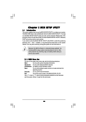
... is constantly being updated, the following selections: Main To set up the system time/date information Advanced To set up the advanced BIOS features H/W Monitor To display current hardware status Boot To set up the default system device to get into the sub screen. 40 If you start ... turning the system off and then back on. Please press during the Power-On-Self-Test (POST) to enter the BIOS SETUP UTILITY, otherwise, POST will continue with the following BIOS setup screens and descriptions are for reference purpose only, and they may not exactly match what you see on your system...
... is constantly being updated, the following selections: Main To set up the system time/date information Advanced To set up the advanced BIOS features H/W Monitor To display current hardware status Boot To set up the default system device to get into the sub screen. 40 If you start ... turning the system off and then back on. Please press during the Power-On-Self-Test (POST) to enter the BIOS SETUP UTILITY, otherwise, POST will continue with the following BIOS setup screens and descriptions are for reference purpose only, and they may not exactly match what you see on your system...

User Manual
Page 41
... UTILITY Main Advanced H/W Monitor Boot Security Exit System Overview System Time System Date [14:00:09] [Fri 07/20/2007] BIOS Version : 4Core1333-eSATA2 P1.00 Processor Type : Intel (R) CPU 2160 @ 1.80GHz (64bit) Processor Speed : 1800MHz Microcode Update : 6F2/56 Cache Size : 1024KB Total Memory DDRII 1 DDRII 2 ... selected screen To display the General Help Screen To load optimal default values for all the settings To save changes and exit the BIOS SETUP UTILITY To jump to configure system Time. +Tab F1 F9 F10 ESC Select Screen Select Item Change Field Select Field General...
... UTILITY Main Advanced H/W Monitor Boot Security Exit System Overview System Time System Date [14:00:09] [Fri 07/20/2007] BIOS Version : 4Core1333-eSATA2 P1.00 Processor Type : Intel (R) CPU 2160 @ 1.80GHz (64bit) Processor Speed : 1800MHz Microcode Update : 6F2/56 Cache Size : 1024KB Total Memory DDRII 1 DDRII 2 ... selected screen To display the General Help Screen To load optimal default values for all the settings To save changes and exit the BIOS SETUP UTILITY To jump to configure system Time. +Tab F1 F9 F10 ESC Select Screen Select Item Change Field Select Field General...
User Manual
Page 42
... Use this option to adjust CPU frequency. Setting wrong values in below sections may cause the system to malfunction. 3.3.1 CPU Configuration BIOS SETUP UTILITY Advanced CPU Configuration Overclock Mode CPU Frequency (MHz) PCIE Frequency (MHz) Boot Failure Guard Spread Spectrum Ratio Actual Value ... [Auto], [CPU, PCIE, Sync.] and [CPU, PCIE, Async.]. Overclock Mode Use this section may cause system to malfunction. BIOS SETUP UTILITY Main Advanced H/W Monitor Boot Security Exit Advanced Settings WARNING : Setting wrong values in this to select Overclock Mode.
... Use this option to adjust CPU frequency. Setting wrong values in below sections may cause the system to malfunction. 3.3.1 CPU Configuration BIOS SETUP UTILITY Advanced CPU Configuration Overclock Mode CPU Frequency (MHz) PCIE Frequency (MHz) Boot Failure Guard Spread Spectrum Ratio Actual Value ... [Auto], [CPU, PCIE, Sync.] and [CPU, PCIE, Async.]. Overclock Mode Use this section may cause system to malfunction. BIOS SETUP UTILITY Main Advanced H/W Monitor Boot Security Exit Advanced Settings WARNING : Setting wrong values in this to select Overclock Mode.
User Manual
Page 44
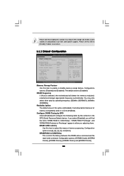
... to allow remapping of memory accessing. The default value is [Disabled]. Flexibility Option The default value of overlapped PCI memory above issue occurs. 3.3.2 Chipset Configuration BIOS SETUP UTILITY Advanced Chipset Configuration Memory Remap Feature [Disabled] DRAM Frequency [Auto] Flexibility Option [Disabled] Configure DRAM Timing by the contents in the SPD (Serial...
... to allow remapping of memory accessing. The default value is [Disabled]. Flexibility Option The default value of overlapped PCI memory above issue occurs. 3.3.2 Chipset Configuration BIOS SETUP UTILITY Advanced Chipset Configuration Memory Remap Feature [Disabled] DRAM Frequency [Auto] Flexibility Option [Disabled] Configure DRAM Timing by the contents in the SPD (Serial...
User Manual
Page 46
... Change Option General Help Load Defaults Save and Exit Exit v02.54 (C) Copyright 1985-2005, American Megatrends, Inc. Select [Auto] will be hidden. 3.3.3 ACPI Configuration BIOS SETUP UTILITY Advanced ACPI Configuration Suspend To RAM Repost Video on STR Resume Restore on STR Resume" will enable this feature if the OS supports...
... Change Option General Help Load Defaults Save and Exit Exit v02.54 (C) Copyright 1985-2005, American Megatrends, Inc. Select [Auto] will be hidden. 3.3.3 ACPI Configuration BIOS SETUP UTILITY Advanced ACPI Configuration Suspend To RAM Repost Video on STR Resume Restore on STR Resume" will enable this feature if the OS supports...
User Manual
Page 47
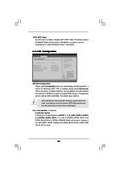
...] when Native OS (Win 2000/XP) is [AHCI]. The default value is used . If it is set to submit Windows® VistaTM certification. 3.3.4 IDE Configuration BIOS SETUP UTILITY Advanced IDE Configuration ATA/IDE Configuration Configure SATA as ", you are allowed to set this option to [Enabled] if you install legacy OS...
...] when Native OS (Win 2000/XP) is [AHCI]. The default value is used . If it is set to submit Windows® VistaTM certification. 3.3.4 IDE Configuration BIOS SETUP UTILITY Advanced IDE Configuration ATA/IDE Configuration Configure SATA as ", you are allowed to set this option to [Enabled] if you install legacy OS...

User Manual
Page 48
... (Port0), SATAII_BLACK (Port1) SATAII_BLUE (Port0) SATAII_RED (Port2), SATAII_ORANGE (Port3) SATAII_RED (Port2) [IDE1, SATA1, SATA3] SATAII_BLACK (Port1) SATAII_ORANGE (Port3) BIOS SETUP UTILITY Advanced Primary IDE Master Device Vendor Size LBA Mode Block Mode PIO Mode Async DMA Ultra DMA S.M.A.R.T. After selecting the hard disk information... into BIOS, use of device connected to choose [SATA0, 1, 2, 3], [IDE1, SATA1, SATA3], and [SATA0, SATA2, IDE1] when...
... (Port0), SATAII_BLACK (Port1) SATAII_BLUE (Port0) SATAII_RED (Port2), SATAII_ORANGE (Port3) SATAII_RED (Port2) [IDE1, SATA1, SATA3] SATAII_BLACK (Port1) SATAII_ORANGE (Port3) BIOS SETUP UTILITY Advanced Primary IDE Master Device Vendor Size LBA Mode Block Mode PIO Mode Async DMA Ultra DMA S.M.A.R.T. After selecting the hard disk information... into BIOS, use of device connected to choose [SATA0, 1, 2, 3], [IDE1, SATA1, SATA3], and [SATA0, SATA2, IDE1] when...
User Manual
Page 50
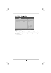
3.3.5 PCIPnP Configuration BIOS SETUP UTILITY Advanced Advanced PCI / PnP Settings PCI Latency Timer PCI IDE BusMaster [32] [Enabled] Value in units of PCI clocks for PCI device latency ...
3.3.5 PCIPnP Configuration BIOS SETUP UTILITY Advanced Advanced PCI / PnP Settings PCI Latency Timer PCI IDE BusMaster [32] [Enabled] Value in units of PCI clocks for PCI device latency ...

User Manual
Page 51
...Option General Help Load Defaults Save and Exit Exit v02.54 (C) Copyright 1985-2005, American Megatrends, Inc. 3.3.7 Super IO Configuration BIOS SETUP UTILITY Advanced Configure Win627EHF Super IO Chipset OnBoard Floppy Controller Serial Port Address Parallel Port Address Parallel Port Mode EPP Version ECP Mode... IRQ OnBoard Game Port OnBoard MIDI Port [Enabled] [3F8 / IRQ4] [378] [ECP + EPP] [1.9] [DMA3] [IRQ7] [Auto] [Disabled] Allow BIOS to Enable or Disable Floppy Controller. +F1 F9 F10 ESC Select Screen Select Item Change Option General Help Load Defaults Save and Exit Exit v02...
...Option General Help Load Defaults Save and Exit Exit v02.54 (C) Copyright 1985-2005, American Megatrends, Inc. 3.3.7 Super IO Configuration BIOS SETUP UTILITY Advanced Configure Win627EHF Super IO Chipset OnBoard Floppy Controller Serial Port Address Parallel Port Address Parallel Port Mode EPP Version ECP Mode... IRQ OnBoard Game Port OnBoard MIDI Port [Enabled] [3F8 / IRQ4] [378] [ECP + EPP] [1.9] [DMA3] [IRQ7] [Auto] [Disabled] Allow BIOS to Enable or Disable Floppy Controller. +F1 F9 F10 ESC Select Screen Select Item Change Option General Help Load Defaults Save and Exit Exit v02...

User Manual
Page 53
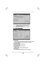
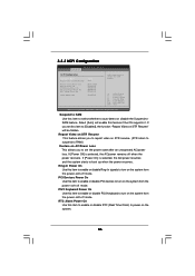
... will start to monitor the status of the hardware on your system, including the parameters of USB controller. 3.3.8 USB Configuration BIOS SETUP UTILITY Advanced USB Configuration USB Controller USB 2.0 Support Legacy USB Support [Enabled] [Enabled] [Disabled] To enable or disable...to enable or disable the use of the CPU temperature, motherboard temperature, CPU fan speed, chassis fan speed, and the critical voltage. etc. BIOS SETUP UTILITY Main Advanced H/W Monitor Boot Security Exit Hardware Health Event Monitoring CPU Temperature M / B Temperature : 37 C / 98 F :...
... will start to monitor the status of the hardware on your system, including the parameters of USB controller. 3.3.8 USB Configuration BIOS SETUP UTILITY Advanced USB Configuration USB Controller USB 2.0 Support Legacy USB Support [Enabled] [Enabled] [Disabled] To enable or disable...to enable or disable the use of the CPU temperature, motherboard temperature, CPU fan speed, chassis fan speed, and the critical voltage. etc. BIOS SETUP UTILITY Main Advanced H/W Monitor Boot Security Exit Hardware Health Event Monitoring CPU Temperature M / B Temperature : 37 C / 98 F :...


