Installation Guide
Page 13
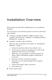
...f Connect the interface cables to the controller card. Installing the Battery Backup Unit" on the controller. (For details, see "Installing the Hardware" on the system. a Connect the interface cables to the drives. www.3ware.com 5 d Insert the controller card into the computer. charge, which... you have a Battery Backup Unit (BBU), install it on page 99.) „ Install the controller, cables, and drives. Installation Overview Details about each step...
...f Connect the interface cables to the controller card. Installing the Battery Backup Unit" on the controller. (For details, see "Installing the Hardware" on the system. a Connect the interface cables to the drives. www.3ware.com 5 d Insert the controller card into the computer. charge, which... you have a Battery Backup Unit (BBU), install it on page 99.) „ Install the controller, cables, and drives. Installation Overview Details about each step...
Installation Guide
Page 15
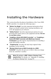
... A. Installing the Hardware This section describes the physical installation of the 3ware 9000 RAID controllers. Installing the Battery Backup Unit" on page 99. www.3ware.com 7 It contains the following topics: „ "Before You ...Begin" provides important information about things you should consider before starting installation, and tools and equipment you change from one controller to protect your equipment and data. Note: If you have a BBU...
... A. Installing the Hardware This section describes the physical installation of the 3ware 9000 RAID controllers. Installing the Battery Backup Unit" on page 99. www.3ware.com 7 It contains the following topics: „ "Before You ...Begin" provides important information about things you should consider before starting installation, and tools and equipment you change from one controller to protect your equipment and data. Note: If you have a BBU...
Installation Guide
Page 20
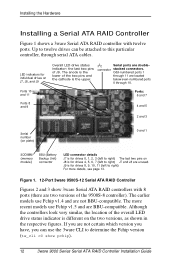
...3ware Serial ATA RAID controllers with twelve ports. I2C Serial ports are BBU-compatible. LED indicators for individual drives on J7, J8, and J9 Overall LED drive status indicator: the last two pins of the overall LED drive status indicator is different on J8 is the lower of the 9500S-8 controller...). Up to twelve drives can use Pchip v1.4 and are unused. Figure 1. 12-Port 3ware 9500S-12 Serial ATA RAID Controller Figures 2 and 3 show pchip). 12 3ware 9000 Series Serial ATA RAID Controller Installation Guide The anode is for...
...3ware Serial ATA RAID controllers with twelve ports. I2C Serial ports are BBU-compatible. LED indicators for individual drives on J7, J8, and J9 Overall LED drive status indicator: the last two pins of the overall LED drive status indicator is different on J8 is the lower of the 9500S-8 controller...). Up to twelve drives can use Pchip v1.4 and are unused. Figure 1. 12-Port 3ware 9500S-12 Serial ATA RAID Controller Figures 2 and 3 show pchip). 12 3ware 9000 Series Serial ATA RAID Controller Installation Guide The anode is for...
Installation Guide
Page 21
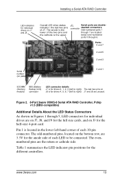
... is the lower of each LED to right) The last two pins on J3 for the half-size 4-port card. www.3ware.com 13 Figure 2. 8-Port 3ware 9500S-8 Serial ATA RAID Controller, Pchip v1.5 (BBU-compatible) Additional Details About the LED Status Connectors As shown in the lower left to be connected. The odd-numbered pins...
... is the lower of each LED to right) The last two pins on J3 for the half-size 4-port card. www.3ware.com 13 Figure 2. 8-Port 3ware 9500S-8 Serial ATA RAID Controller, Pchip v1.5 (BBU-compatible) Additional Details About the LED Status Connectors As shown in the lower left to be connected. The odd-numbered pins...
Installation Guide
Page 23
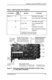
... J7 is for drives 0, 1, 2, 3 (left to right) J8 is for individual drives on J7 and J8 are unused. Installing a Serial ATA RAID Controller Table 1: LED Indicator Pin Positions Controller LED Header Pin Pair 9500S-12 J7 : : : : : 0 1 2 3 NU Comment Orientation Horizontal Port number/NU (Not Used) J8 : : : : : Orientation Horizontal 4 5 6 7 NU Port ... and the cathode is the upper. Odd-numbered ports 1 through 7 are double- The anode is the lower of J9. Figure 3. 8-Port 3ware 9500S-8 Serial ATA RAID Controller, Pchip v1.4 (Non-BBU Compatible) www.3ware.com 15
... J7 is for drives 0, 1, 2, 3 (left to right) J8 is for individual drives on J7 and J8 are unused. Installing a Serial ATA RAID Controller Table 1: LED Indicator Pin Positions Controller LED Header Pin Pair 9500S-12 J7 : : : : : 0 1 2 3 NU Comment Orientation Horizontal Port number/NU (Not Used) J8 : : : : : Orientation Horizontal 4 5 6 7 NU Port ... and the cathode is the upper. Odd-numbered ports 1 through 7 are double- The anode is the lower of J9. Figure 3. 8-Port 3ware 9500S-8 Serial ATA RAID Controller, Pchip v1.4 (Non-BBU Compatible) www.3ware.com 15
Installation Guide
Page 24
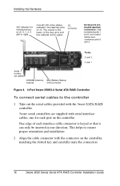
..., one direction. Ports: 2 and 3 0 and 1 Serial number (on plate) SODIMM (memory module) BBU (Battery Backup Unit) connector Figure 4. 4-Port 3ware 9500S-4 Serial ATA RAID Controller To connect serial cables to right) Overall LED drive status indicator: the last two pins of each port on... the controller. Installing the Hardware LED indicators for each interface cable connector is the upper. ...
..., one direction. Ports: 2 and 3 0 and 1 Serial number (on plate) SODIMM (memory module) BBU (Battery Backup Unit) connector Figure 4. 4-Port 3ware 9500S-4 Serial ATA RAID Controller To connect serial cables to right) Overall LED drive status indicator: the last two pins of each port on... the controller. Installing the Hardware LED indicators for each interface cable connector is the upper. ...

Installation Guide
Page 27
For more details, see page 16. Figure 5. 12-Port 3ware 9500S-12MI Serial ATA RAID Controller Models 9500S-12MI and 9500S-8MI, have : „ For use the InfiniBand 4x cable, which has multi-lane connectors on each of which can be installed in Figure 6. ... Internal Connectors Installing a Serial ATA RAID Controller with Multi-lane Internal Connectors I2C LED indicators for connector individual drives on J8 and J9 is for drives 8, 9, 10, 11 (top to bottom) J9 are unused. Ports 8 to 11 Ports 4 to 7 Ports 0 to 3 Serial number (on plate) BBU (Battery Backup Unit) connector SODIMM ...
For more details, see page 16. Figure 5. 12-Port 3ware 9500S-12MI Serial ATA RAID Controller Models 9500S-12MI and 9500S-8MI, have : „ For use the InfiniBand 4x cable, which has multi-lane connectors on each of which can be installed in Figure 6. ... Internal Connectors Installing a Serial ATA RAID Controller with Multi-lane Internal Connectors I2C LED indicators for connector individual drives on J8 and J9 is for drives 8, 9, 10, 11 (top to bottom) J9 are unused. Ports 8 to 11 Ports 4 to 7 Ports 0 to 3 Serial number (on plate) BBU (Battery Backup Unit) connector SODIMM ...
Installation Guide
Page 46
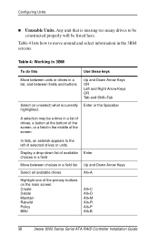
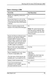
... drives Highlight one of the primary buttons on the main screen: Create Delete Maintain Rebuild Policy BBU Enter Up and Down Arrow Keys Alt+A Alt+C Alt+D Alt+M Alt+R Alt+P Alt+B 38 3ware 9000 Series Serial ATA RAID Controller Installation Guide Display a drop-down list of available choices in a field Move between fields and buttons...
... drives Highlight one of the primary buttons on the main screen: Create Delete Maintain Rebuild Policy BBU Enter Up and Down Arrow Keys Alt+A Alt+C Alt+D Alt+M Alt+R Alt+P Alt+B 38 3ware 9000 Series Serial ATA RAID Controller Installation Guide Display a drop-down list of available choices in a field Move between fields and buttons...
Installation Guide
Page 47
... can see the software versions (BIOS, Firmware, monitor), serial number, controller and model number, cache memory size, slot # of the 3ware card, and whether or not BBU-support is available.) Shift+F5 Return to the main 3ware BIOS Manager screen, from the Advanced Details screen Any key Move a highlighted...will become the bootable unit, if you install the OS.) Page Up Page Down [Available only when there are saved when you have multiple 3ware Esc controllers in your system, return to starting values for this Use these keys Specify (or unspecify) a drive as a S hot spare Unlock the...
... can see the software versions (BIOS, Firmware, monitor), serial number, controller and model number, cache memory size, slot # of the 3ware card, and whether or not BBU-support is available.) Shift+F5 Return to the main 3ware BIOS Manager screen, from the Advanced Details screen Any key Move a highlighted...will become the bootable unit, if you install the OS.) Page Up Page Down [Available only when there are saved when you have multiple 3ware Esc controllers in your system, return to starting values for this Use these keys Specify (or unspecify) a drive as a S hot spare Unlock the...
Installation Guide
Page 107
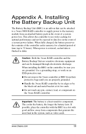
...Use a grounding strap, or work on an ESD-protective mat. „ Do not remove the 3ware controller or BBU from components that can be sure you are properly grounded. „ Handle the 3ware RAID controller by its edges or by the black rail and metal bracket at its two ends. „ Do...of time (up to data loss in the event of a system power failure. Caution: Both the 3ware RAID controller and the Battery Backup Unit are grounded. If possible, place the controller with the BBU in a slot with good airflow, away from their protective bags until you are sensitive electronic equipment ...
...Use a grounding strap, or work on an ESD-protective mat. „ Do not remove the 3ware controller or BBU from components that can be sure you are properly grounded. „ Handle the 3ware RAID controller by its edges or by the black rail and metal bracket at its two ends. „ Do...of time (up to data loss in the event of a system power failure. Caution: Both the 3ware RAID controller and the Battery Backup Unit are grounded. If possible, place the controller with the BBU in a slot with good airflow, away from their protective bags until you are sensitive electronic equipment ...
Installation Guide
Page 108
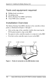
... on the BBU a) Clips b) BBU connector c) post Figure 1. Installing the Battery Backup Unit Tools and equipment required „ Phillips-head screwdriver „ Grounding strap „ Battery Backup Unit (BBU) and battery „ 3ware 9000 series controller Installation Overview The Battery Backup Unit (BBU) attaches to post on the BBU (bottom view) 100 3ware 9000 Series Serial ATA RAID Controller Installation...
... on the BBU a) Clips b) BBU connector c) post Figure 1. Installing the Battery Backup Unit Tools and equipment required „ Phillips-head screwdriver „ Grounding strap „ Battery Backup Unit (BBU) and battery „ 3ware 9000 series controller Installation Overview The Battery Backup Unit (BBU) attaches to post on the BBU (bottom view) 100 3ware 9000 Series Serial ATA RAID Controller Installation...
Installation Guide
Page 109
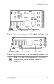
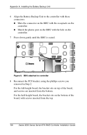
Installation Overview a) Slots on the edge b) BBU receptacle c) Hole for post Figure 3. www.3ware.com 101 Points of connection on the half-height controller (top view) Note: If your 9000 series controller does not have the BBU receptacle, contact technical support for post Figure 2. Points of connection on the full-height controller (top view) a) Slots on the edge b) BBU receptacle c) Hole for assistance.
Installation Overview a) Slots on the edge b) BBU receptacle c) Hole for post Figure 3. www.3ware.com 101 Points of connection on the half-height controller (top view) Note: If your 9000 series controller does not have the BBU receptacle, contact technical support for post Figure 2. Points of connection on the full-height controller (top view) a) Slots on the edge b) BBU receptacle c) Hole for assistance.
Installation Guide
Page 111
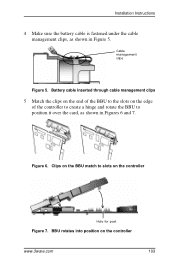
Figure 6. Clips on the BBU match to position it over the card, as shown in Figures 6 and 7. Battery cable inserted through cable management clips 5 Match the clips on the end of the BBU to the slots on the edge of the controller to create a hinge and rotate the BBU to slots on the controller www.3ware.com 103 Installation Instructions 4 Make sure the battery cable is fastened under the cable management clips, as shown in Figure 5. BBU rotates into position on the controller Hole for post Figure 7. Cable management clips Figure 5.
Figure 6. Clips on the BBU match to position it over the card, as shown in Figures 6 and 7. Battery cable inserted through cable management clips 5 Match the clips on the end of the BBU to the slots on the edge of the controller to create a hinge and rotate the BBU to slots on the controller www.3ware.com 103 Installation Instructions 4 Make sure the battery cable is fastened under the cable management clips, as shown in Figure 5. BBU rotates into position on the controller Hole for post Figure 7. Cable management clips Figure 5.
Installation Guide
Page 112
... the board, and screws are inserted from the top. 104 3ware 9000 Series Serial ATA RAID Controller Installation Guide BBU attached to the controller with these connectors: „ Mate the connector on the BBU with the receptacle on the controller. „ Match the plastic post on the BBU with screws inserted from the bottom. Appendix A. Installing the Battery...
... the board, and screws are inserted from the top. 104 3ware 9000 Series Serial ATA RAID Controller Installation Guide BBU attached to the controller with these connectors: „ Mate the connector on the BBU with the receptacle on the controller. „ Match the plastic post on the BBU with screws inserted from the bottom. Appendix A. Installing the Battery...
Installation Guide
Page 113
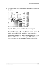
Installation Instructions 9 Insert the battery power connector into the power receptacle on 3ware controllers. Battery power connector and power receptacle The controller is now ready to be replaced. www.3ware.com 105 Figures 10 and 11 show the BBU fully installed on the BBU. For details, see 3ware 9000 Series Serial ATA RAID Controller User Guide. Figure 9. You can check the status of the battery, and run a battery test to determine if the battery needs to install in your system.
Installation Instructions 9 Insert the battery power connector into the power receptacle on 3ware controllers. Battery power connector and power receptacle The controller is now ready to be replaced. www.3ware.com 105 Figures 10 and 11 show the BBU fully installed on the BBU. For details, see 3ware 9000 Series Serial ATA RAID Controller User Guide. Figure 9. You can check the status of the battery, and run a battery test to determine if the battery needs to install in your system.
Installation Guide
Page 114
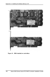
Installing the Battery Backup Unit Figure 10. BBU installed on controllers 106 3ware 9000 Series Serial ATA RAID Controller Installation Guide Appendix A.
Installing the Battery Backup Unit Figure 10. BBU installed on controllers 106 3ware 9000 Series Serial ATA RAID Controller Installation Guide Appendix A.
Installation Guide
Page 115
... battery has an expected life span of the battery, and test it. For details, see instructions in 3ware 9000 Series Serial ATA RAID Controller User Guide. To obtain a replacement battery, contact AMCC. You can check the current status of one ...to two years depending on usage. For proper battery disposal resources, contact RBRC, The Rechargeable Battery Recycling Corporation (www.rbrc.com). Replacing the Battery Replacing the Battery The Battery Backup Unit (BBU...
... battery has an expected life span of the battery, and test it. For details, see instructions in 3ware 9000 Series Serial ATA RAID Controller User Guide. To obtain a replacement battery, contact AMCC. You can check the current status of one ...to two years depending on usage. For proper battery disposal resources, contact RBRC, The Rechargeable Battery Recycling Corporation (www.rbrc.com). Replacing the Battery Replacing the Battery The Battery Backup Unit (BBU...
Installation Guide
Page 116
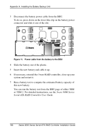
... to compute the estimated battery capacity of the slot. For detailed instructions, see the 3ware 9000 Series Serial ATA RAID Controller User Guide. 108 3ware 9000 Series Serial ATA RAID Controller Installation Guide Power cable from the BBU page of either 3BM or 3DM 2. You can run the battery test from the ...battery to the BBU 4 Slide the battery out of the plastic. 5 Insert the new battery and cable it up. 6 If necessary, reinstall the 3ware RAID controller, close up your system and restart it out of this new battery. Figure ...
... to compute the estimated battery capacity of the slot. For detailed instructions, see the 3ware 9000 Series Serial ATA RAID Controller User Guide. 108 3ware 9000 Series Serial ATA RAID Controller Installation Guide Power cable from the BBU page of either 3BM or 3DM 2. You can run the battery test from the ...battery to the BBU 4 Slide the battery out of the plastic. 5 Insert the new battery and cable it up. 6 If necessary, reinstall the 3ware RAID controller, close up your system and restart it out of this new battery. Figure ...
Installation Guide
Page 120
Appendix C. Products or parts replaced under this provision shall become the property of purchase. 112 3ware 9000 Series Serial ATA RAID Controller Installation Guide Software Warranty: AMCC will replace a defective media purchased with this product which proves defective by reason of...against defects in material and workmanship for a period of thirty-six (36) months from the date of original purchase. Battery Backup Unit (BBU) Hardware. 1-Year Hardware Warranty: AMCC warrants this product against defects in material and workmanship for a period of twelve (12) months from...
Appendix C. Products or parts replaced under this provision shall become the property of purchase. 112 3ware 9000 Series Serial ATA RAID Controller Installation Guide Software Warranty: AMCC will replace a defective media purchased with this product which proves defective by reason of...against defects in material and workmanship for a period of thirty-six (36) months from the date of original purchase. Battery Backup Unit (BBU) Hardware. 1-Year Hardware Warranty: AMCC warrants this product against defects in material and workmanship for a period of twelve (12) months from...
Installation Guide
Page 125
... in 38 A Accelerated Graphics Port (AGP) 8 auto-carving 33, 47 B backplane, using with multi-lane connectors 19 BBU (battery backup unit) installation 99 replacing the battery 99 BIOS Manager 34 C cable length, routing space, air flow 8 ...Compliance and Conformity 109 configuring BIOS Manager 34 determining RAID level to use 31 initializing units 49 RAID concepts and levels 28 units 40 using 3BM 38 D distributed parity 29 drive capacity 32 drive... I initializing units 49 installing cables 8 drive considerations 9 driver under FreeBSD 87 www.3ware.com 117
... in 38 A Accelerated Graphics Port (AGP) 8 auto-carving 33, 47 B backplane, using with multi-lane connectors 19 BBU (battery backup unit) installation 99 replacing the battery 99 BIOS Manager 34 C cable length, routing space, air flow 8 ...Compliance and Conformity 109 configuring BIOS Manager 34 determining RAID level to use 31 initializing units 49 RAID concepts and levels 28 units 40 using 3BM 38 D distributed parity 29 drive capacity 32 drive... I initializing units 49 installing cables 8 drive considerations 9 driver under FreeBSD 87 www.3ware.com 117