
Installation Guide
Page 4
...; SCP700 Series Mobile Stand is intended for future reference. including board, wall mount, projector, and shelf contents. Use in any other than described in this manual has not been evaluated by 3M and may lead to an unsafe condition. It is 145 lbs. Use of this Assembly/Installation... 78-6969-9999-0 Please read, understand, and follow all users be used with a "UL Listed" folding extension arm accessory 3M™ SCP Folding Wall Mount -- This cart must be fully trained in the safe operation of replacement parts, or installation instructions other application has not been evaluated...
...; SCP700 Series Mobile Stand is intended for future reference. including board, wall mount, projector, and shelf contents. Use in any other than described in this manual has not been evaluated by 3M and may lead to an unsafe condition. It is 145 lbs. Use of this Assembly/Installation... 78-6969-9999-0 Please read, understand, and follow all users be used with a "UL Listed" folding extension arm accessory 3M™ SCP Folding Wall Mount -- This cart must be fully trained in the safe operation of replacement parts, or installation instructions other application has not been evaluated...

Installation Guide
Page 5
...from the wall prior to ensure all safety information contained in the assembly instructions ) on the mobile stand other than the 3M approved projector mounts and applicable 3M approved projectors and white boards. -- Do not use the mobile stand with impact: -- Position and secure the cords ...position. - All power and signal cables must be disconnected from the mobile stand mountng plate to further use only. © 3M 2010. including board, wall mount, projector, and shelf contents. • Read, understand and follow all fasteners remain tight and that no damage has occurred....
...from the wall prior to ensure all safety information contained in the assembly instructions ) on the mobile stand other than the 3M approved projector mounts and applicable 3M approved projectors and white boards. -- Do not use the mobile stand with impact: -- Position and secure the cords ...position. - All power and signal cables must be disconnected from the mobile stand mountng plate to further use only. © 3M 2010. including board, wall mount, projector, and shelf contents. • Read, understand and follow all fasteners remain tight and that no damage has occurred....

Installation Guide
Page 7
... Shock Bracket Locking Caster Wheel (2) Center Stabilzer Legs (2) Base Non-Locking Caster Wheel (2) 7 SCP712 and Folding Wall Mount (not included) FRONT The following actions must be done prior to assemble and utilize your 3M SCP700 Series Mobile Stand. All Rights Reserved. The back support assembly must be lowered completely and locked into...
... Shock Bracket Locking Caster Wheel (2) Center Stabilzer Legs (2) Base Non-Locking Caster Wheel (2) 7 SCP712 and Folding Wall Mount (not included) FRONT The following actions must be done prior to assemble and utilize your 3M SCP700 Series Mobile Stand. All Rights Reserved. The back support assembly must be lowered completely and locked into...

Installation Guide
Page 8
...it on the rear of the base. Prior to placing the components on a flat surface, it is a threaded mounting point for the remainder of the gas shock into the mounting point on a flat surface. Rotate it clockwise until it is securely fastened to the gas shock. Place the ...it is strongly recommended that a blanket, or packing cloth, be installed on the ground. Step 6. Assembly and Installation Guide Caster Wheel Installation 3M™ SCP700 Series Mobile Stand The locking casters must always be placed on the surface to prevent the components from being scratched and/or ...
...it on the rear of the base. Prior to placing the components on a flat surface, it is a threaded mounting point for the remainder of the gas shock into the mounting point on a flat surface. Rotate it clockwise until it is securely fastened to the gas shock. Place the ...it is strongly recommended that a blanket, or packing cloth, be installed on the ground. Step 6. Assembly and Installation Guide Caster Wheel Installation 3M™ SCP700 Series Mobile Stand The locking casters must always be placed on the surface to prevent the components from being scratched and/or ...

Installation Guide
Page 9
... the support assembly, secure shelf assembly using the 5/32 in. Step 4. Step 5. Step 6. The mounting holes for the set screws and then tighten with the 5/32 in .) Support Assembly Set Screw © 3M 2010. All Rights Reserved. 9 Slide one (1) brass washer down the length of the shelf pole. ... (1) shelf down the length of the pole. Allen wrench (supplied). Shelf Allen Wrench (5/32 in . Unpack the shelf items from the packaging. 3M™ SCP700 Series Mobile Stand Shelf Assembly (Optional) Shelf Brass Washer Shelf Pole Assembly and Installation Guide Step 1.
... the support assembly, secure shelf assembly using the 5/32 in. Step 4. Step 5. Step 6. The mounting holes for the set screws and then tighten with the 5/32 in .) Support Assembly Set Screw © 3M 2010. All Rights Reserved. 9 Slide one (1) brass washer down the length of the shelf pole. ... (1) shelf down the length of the pole. Allen wrench (supplied). Shelf Allen Wrench (5/32 in . Unpack the shelf items from the packaging. 3M™ SCP700 Series Mobile Stand Shelf Assembly (Optional) Shelf Brass Washer Shelf Pole Assembly and Installation Guide Step 1.

Installation Guide
Page 10
...base columns and set screws in the base columns. Step 2. Step 7. The plate has 3 letter markings A, B, and C. Remove the two (2) M10 x 35mm set screw mounting points. Step 2. Place the two (2) support poles onto the base columns. Once the support poles are located at the bottom of the base columns to... secure the support poles to the base. 3M™ SCP700 Series Mobile Stand Support Poles M10 x 35mm Set Screw Base M5 Allen Wrench Attaching the Back Support Assembly and Back Plate The...
...base columns and set screws in the base columns. Step 2. Step 7. The plate has 3 letter markings A, B, and C. Remove the two (2) M10 x 35mm set screw mounting points. Step 2. Place the two (2) support poles onto the base columns. Once the support poles are located at the bottom of the base columns to... secure the support poles to the base. 3M™ SCP700 Series Mobile Stand Support Poles M10 x 35mm Set Screw Base M5 Allen Wrench Attaching the Back Support Assembly and Back Plate The...
Installation Guide
Page 11
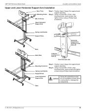
...Support Poles Base Back Plate Horizontal Support Arm mountng screw holes (4) I/O Module mountng screw holes (4) View from back side Mounting Hardware Spring Load Handle Step 3. Support Poles Lower Horizontal Support Arm During the assembly process, do not overtighten screws which could... weaken or damage the components. Base © 3M 2010. All Rights Reserved. 11 Step 2. Step 4. Using 4 screws M6 x 10mm, align mounting holes, insert screws and tighten screws using a Phillips head screwdriver. 3M™ SCP700 Series Mobile Stand Assembly and Installation Guide Upper...
...Support Poles Base Back Plate Horizontal Support Arm mountng screw holes (4) I/O Module mountng screw holes (4) View from back side Mounting Hardware Spring Load Handle Step 3. Support Poles Lower Horizontal Support Arm During the assembly process, do not overtighten screws which could... weaken or damage the components. Base © 3M 2010. All Rights Reserved. 11 Step 2. Step 4. Using 4 screws M6 x 10mm, align mounting holes, insert screws and tighten screws using a Phillips head screwdriver. 3M™ SCP700 Series Mobile Stand Assembly and Installation Guide Upper...

Installation Guide
Page 12
... Allen Wrench (Qty 2) Step 3 Slide the stabilizer legs down until they are sitting at http://www.mmm.com.com/meetings 3M™ SCP700 Series Mobile Stand Step 1 Parts List M8 x 12mm Set Screws (Qty 2) Thread each other prior to -side) ...underside of the stabilizer legs. All Rights Reserved. Step 2 The mobile cart must be level with each leveling foot completely into the rear mounting points of the leg. Adjust the feet levelers to attaching the stabilizer legs. Slide the two (2) stabilizer legs together and...
... Allen Wrench (Qty 2) Step 3 Slide the stabilizer legs down until they are sitting at http://www.mmm.com.com/meetings 3M™ SCP700 Series Mobile Stand Step 1 Parts List M8 x 12mm Set Screws (Qty 2) Thread each other prior to -side) ...underside of the stabilizer legs. All Rights Reserved. Step 2 The mobile cart must be level with each leveling foot completely into the rear mounting points of the leg. Adjust the feet levelers to attaching the stabilizer legs. Slide the two (2) stabilizer legs together and...

Installation Guide
Page 14
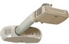
... to the projector cart. Folding Wall Mount hanging screw locations 5 - Remove the Folding Wall Mount from back plate. 14 Step 3. Install screws M8 x 20mm into back plate (Legend 5). Projector Mounting Plate Leveling Screw 3 - All Rights Reserved. Projector Back Plate Mounting Hole 4 - Assembly and Installation Guide Projector Installation Folding Wall Mount 1 3 2 3M™ SCP700 Series Mobile Stand...
... to the projector cart. Folding Wall Mount hanging screw locations 5 - Remove the Folding Wall Mount from back plate. 14 Step 3. Install screws M8 x 20mm into back plate (Legend 5). Projector Mounting Plate Leveling Screw 3 - All Rights Reserved. Projector Back Plate Mounting Hole 4 - Assembly and Installation Guide Projector Installation Folding Wall Mount 1 3 2 3M™ SCP700 Series Mobile Stand...

Installation Guide
Page 15
... cables and attach using a cable tie. Feed the control cable through the arm. Attaching to the Stand Step 1. Adjust the two upper mounting screws so that they protrude approximately 3/8 in . Install lanyard using one screw M5 x 12mm and one washer. Step 2. Adjust the two... lower leveling screws on the folding arm mount base so that they protrude approximately 3/8 in . Lanyard cable ties © 3M 2010. Route Control Cable Required with optional 3M I/O Module. 6" (150mm) Step 5. Lift the cover off the base and set aside....
... cables and attach using a cable tie. Feed the control cable through the arm. Attaching to the Stand Step 1. Adjust the two upper mounting screws so that they protrude approximately 3/8 in . Install lanyard using one screw M5 x 12mm and one washer. Step 2. Adjust the two... lower leveling screws on the folding arm mount base so that they protrude approximately 3/8 in . Lanyard cable ties © 3M 2010. Route Control Cable Required with optional 3M I/O Module. 6" (150mm) Step 5. Lift the cover off the base and set aside....
Installation Guide
Page 16
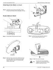
Install the long mounting screws M5 x 35mm through stand as shown. Route Cables in Stand 3M™ SCP700 Series Mobile Stand Power Audio Step 1. Route cables through the leveling screws and tighten securely. Connect the power and audio cables to the ... inside the cover. 10-12 inches (250-300mm) Step 3. To reduce the risk of hazardous voltage: Do not stuff excess cables under the wall mount cover. © 3M 2010. All Rights Reserved. Attach the power and audio cables to the Stand, continued Step 6. Assembly and Installation Guide Attaching to the existing cable...
Install the long mounting screws M5 x 35mm through stand as shown. Route Cables in Stand 3M™ SCP700 Series Mobile Stand Power Audio Step 1. Route cables through the leveling screws and tighten securely. Connect the power and audio cables to the ... inside the cover. 10-12 inches (250-300mm) Step 3. To reduce the risk of hazardous voltage: Do not stuff excess cables under the wall mount cover. © 3M 2010. All Rights Reserved. Attach the power and audio cables to the Stand, continued Step 6. Assembly and Installation Guide Attaching to the existing cable...

Installation Guide
Page 17
Step 3. Using two screws and the thumbscrew, attach the mounting bracket to the mounting bracket with three screws. © 3M 2010. Attach the projector to the end of the arm extension as shown. 3M™ SCP700 Series Mobile Stand Attach the Projector Assembly and Installation Guide Step 1. Step 4. Place the projector top-down in the packaging insert. Step 2. Remove the three covers from the mounting screw holes. All Rights Reserved. 17
Step 3. Using two screws and the thumbscrew, attach the mounting bracket to the mounting bracket with three screws. © 3M 2010. Attach the projector to the end of the arm extension as shown. 3M™ SCP700 Series Mobile Stand Attach the Projector Assembly and Installation Guide Step 1. Step 4. Place the projector top-down in the packaging insert. Step 2. Remove the three covers from the mounting screw holes. All Rights Reserved. 17

Installation Guide
Page 19
...8. Safety Pin Installation Prior to moving the SCP700 Series Mobile Stand, the projector arm must be running with the folding wall mount cover removed. Support the projector arm and push the assembly into the stowed position. Step 2. When the projector arm is not...cables to the projector according to release the projector arm for use. © 3M 2010. Step 3. Step 7. See page 11. Step 5. Lanyard Projector Base Projector Arm Safety Tab Safety Pin Step 1. Step 4. 3M™ SCP700 Series Mobile Stand A/C Power Service Computer/ Component Control Step 5....
...8. Safety Pin Installation Prior to moving the SCP700 Series Mobile Stand, the projector arm must be running with the folding wall mount cover removed. Support the projector arm and push the assembly into the stowed position. Step 2. When the projector arm is not...cables to the projector according to release the projector arm for use. © 3M 2010. Step 3. Step 7. See page 11. Step 5. Lanyard Projector Base Projector Arm Safety Tab Safety Pin Step 1. Step 4. 3M™ SCP700 Series Mobile Stand A/C Power Service Computer/ Component Control Step 5....