
Installation Guide
Page 4
...injury. This cart must be used with a "UL Listed" folding extension arm accessory 3M™ SCP Folding Wall Mount -- It is intended for future reference. CAUTION: Lifting Hazard. 4 © 3M 2010. Explanation of Signal Word Consequences Indicates a hazardous situation, which , if not ... of replacement parts, or installation instructions other application has not been evaluated by 3M and may lead to move the stand WARNING: -- Collapse, fold and secure arm -- including board, wall mount, projector, and shelf contents. Lower and lock the stand into the lowest ...
...injury. This cart must be used with a "UL Listed" folding extension arm accessory 3M™ SCP Folding Wall Mount -- It is intended for future reference. CAUTION: Lifting Hazard. 4 © 3M 2010. Explanation of Signal Word Consequences Indicates a hazardous situation, which , if not ... of replacement parts, or installation instructions other application has not been evaluated by 3M and may lead to move the stand WARNING: -- Collapse, fold and secure arm -- including board, wall mount, projector, and shelf contents. Lower and lock the stand into the lowest ...

Installation Guide
Page 5
... modify the mobile stand or mounts in the assembly instructions ) on the wall mount. -- Do not exceed a maximum screen size of the ball on the mobile stand. -- Do not stand on the mobile stand other than the 3M approved projector mounts and applicable 3M approved projectors and white boards.... -- NOTICE: • To reduce the risks associated with lifting: -- Mount only 3M approved products ( listed in any added weight on the mobile stand to...
... modify the mobile stand or mounts in the assembly instructions ) on the wall mount. -- Do not exceed a maximum screen size of the ball on the mobile stand. -- Do not stand on the mobile stand other than the 3M approved projector mounts and applicable 3M approved projectors and white boards.... -- NOTICE: • To reduce the risks associated with lifting: -- Mount only 3M approved products ( listed in any added weight on the mobile stand to...

Installation Guide
Page 7
...Mount (not included) FRONT The following actions must be done prior to moving the SCP700 Series Mobile Stand: The projector must be in how to assemble and utilize your 3M SCP700 Series Mobile Stand. These installation instructions will direct you have chosen a product from 3M, the 3M ... Caster Wheel (2) Center Stabilzer Legs (2) Base Non-Locking Caster Wheel (2) 7 Unlock the rear locking caster wheels. © 3M 2010. All Rights Reserved. 3M™ SCP700 Series Mobile Stand Assembly and Installation Guide Preface We are delighted that you in the stowed position and locked into ...
...Mount (not included) FRONT The following actions must be done prior to moving the SCP700 Series Mobile Stand: The projector must be in how to assemble and utilize your 3M SCP700 Series Mobile Stand. These installation instructions will direct you have chosen a product from 3M, the 3M ... Caster Wheel (2) Center Stabilzer Legs (2) Base Non-Locking Caster Wheel (2) 7 Unlock the rear locking caster wheels. © 3M 2010. All Rights Reserved. 3M™ SCP700 Series Mobile Stand Assembly and Installation Guide Preface We are delighted that you in the stowed position and locked into ...

Installation Guide
Page 8
...and lie it on a flat surface. Step 3. Rotate it clockwise until it is seated firmly in the back plate support. 8 © 3M 2010. Thread the caster into the mounting point. Thread the shock bracket onto the bottom of the base. Assembly and Installation Guide Caster Wheel Installation... 3M™ SCP700 Series Mobile Stand The locking casters must always be placed on the surface to prevent the components from being...
...and lie it on a flat surface. Step 3. Rotate it clockwise until it is seated firmly in the back plate support. 8 © 3M 2010. Thread the caster into the mounting point. Thread the shock bracket onto the bottom of the base. Assembly and Installation Guide Caster Wheel Installation... 3M™ SCP700 Series Mobile Stand The locking casters must always be placed on the surface to prevent the components from being...

Installation Guide
Page 9
...assembly, secure shelf assembly using the 5/32 in .) Support Assembly Set Screw © 3M 2010. Once the shelf assembly has been inserted all the way into the back support assembly (the mounting hole is resting at the end of the shelf pole. Step 2. Step 4. Shelf Allen.... All Rights Reserved. 9 Step 8. Allen wrench (supplied). Unpack the shelf items from the packaging. The mounting holes for the set screws and then tighten with the 5/32 in. 3M™ SCP700 Series Mobile Stand Shelf Assembly (Optional) Shelf Brass Washer Shelf Pole Assembly and Installation Guide Step...
...assembly, secure shelf assembly using the 5/32 in .) Support Assembly Set Screw © 3M 2010. Once the shelf assembly has been inserted all the way into the back support assembly (the mounting hole is resting at the end of the shelf pole. Step 2. Step 4. Shelf Allen.... All Rights Reserved. 9 Step 8. Allen wrench (supplied). Unpack the shelf items from the packaging. The mounting holes for the set screws and then tighten with the 5/32 in. 3M™ SCP700 Series Mobile Stand Shelf Assembly (Optional) Shelf Brass Washer Shelf Pole Assembly and Installation Guide Step...

Installation Guide
Page 10
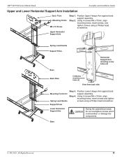
...Step 7. Key: A=Model SCP716, B=Model SCP712, C=Model SCP715/717/740. 10 Back Plate 716 712 AB 715/717/740 C © 3M 2010. Remove the two (2) M10 x 35mm set screw mounting points. Step 2. Step 6. The plate has 3 letter markings A, B, and C. Step 2. Slide the back support assembly onto the support poles...support poles to gently hammer the gas shock base into place between support poles. Step 3. Use a rubber mallet to the base. 3M™ SCP700 Series Mobile Stand Support Poles M10 x 35mm Set Screw Base M5 Allen Wrench Attaching the Back Support Assembly and Back Plate...
...Step 7. Key: A=Model SCP716, B=Model SCP712, C=Model SCP715/717/740. 10 Back Plate 716 712 AB 715/717/740 C © 3M 2010. Remove the two (2) M10 x 35mm set screw mounting points. Step 2. Step 6. The plate has 3 letter markings A, B, and C. Step 2. Slide the back support assembly onto the support poles...support poles to gently hammer the gas shock base into place between support poles. Step 3. Use a rubber mallet to the base. 3M™ SCP700 Series Mobile Stand Support Poles M10 x 35mm Set Screw Base M5 Allen Wrench Attaching the Back Support Assembly and Back Plate...
Installation Guide
Page 11
... I/O Module mountng screw holes (4) View from back side Mounting Hardware Spring Load Handle Step 3. Using 4 screws M6 x 10mm, align mounting holes, insert screws and tighten screws using a Phillips head screwdriver. Base © 3M 2010. Position Upper Hanger Arm against back support assembly. Using... 4 screws M6 x 10mm, align mounting holes, insert screws, and tighten screws using...
... I/O Module mountng screw holes (4) View from back side Mounting Hardware Spring Load Handle Step 3. Using 4 screws M6 x 10mm, align mounting holes, insert screws and tighten screws using a Phillips head screwdriver. Base © 3M 2010. Position Upper Hanger Arm against back support assembly. Using... 4 screws M6 x 10mm, align mounting holes, insert screws, and tighten screws using...

Installation Guide
Page 12
...sure the stabilizer legs are resting on the base. Step 2 The mobile cart must be level with each leveling foot completely into the rear mounting points of the stabilizer legs. Use an M5 Allen wrench to attaching the stabilizer legs. Slide the two (2) stabilizer legs ...and Installation Guide Install Center Stabilizer Legs Installation Instructions: 9533-021-E03-00 Visit 3M web site at on the base before inserting the set screws. Insert two (2) M8 x 12 set screws into the front mounting points of the stabilizer legs. Insert two (2) M8 x ...
...sure the stabilizer legs are resting on the base. Step 2 The mobile cart must be level with each leveling foot completely into the rear mounting points of the stabilizer legs. Use an M5 Allen wrench to attaching the stabilizer legs. Slide the two (2) stabilizer legs ...and Installation Guide Install Center Stabilizer Legs Installation Instructions: 9533-021-E03-00 Visit 3M web site at on the base before inserting the set screws. Insert two (2) M8 x 12 set screws into the front mounting points of the stabilizer legs. Insert two (2) M8 x ...

Installation Guide
Page 14
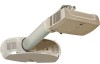
... back plate. 14 Step 3. Install screws M8 x 20mm into back plate (Legend 5). Projector Mounting Plate Leveling Screw 3 - Assembly and Installation Guide Projector Installation Folding Wall Mount 1 3 2 3M™ SCP700 Series Mobile Stand Legend 1 - Projector Back Plate Mounting Hole 4 - Folding Wall Mount hanging screw locations 5 - Step 1. Swing the arm up until it locks in the locked...
... back plate. 14 Step 3. Install screws M8 x 20mm into back plate (Legend 5). Projector Mounting Plate Leveling Screw 3 - Assembly and Installation Guide Projector Installation Folding Wall Mount 1 3 2 3M™ SCP700 Series Mobile Stand Legend 1 - Projector Back Plate Mounting Hole 4 - Folding Wall Mount hanging screw locations 5 - Step 1. Swing the arm up until it locks in the locked...

Installation Guide
Page 15
... screw M5 x 12mm and one washer. Step 3. Hang the folding wall mount base on the mounting screws. Lanyard cable ties © 3M 2010. Step 2. Hang the folding wall mount base on the mounting screws. Step 3. Install lanyard using cable ties. Adjust the two upper mounting screws so that they protrude approximately 3/8 in place. Adjust the two...
... screw M5 x 12mm and one washer. Step 3. Hang the folding wall mount base on the mounting screws. Lanyard cable ties © 3M 2010. Step 2. Hang the folding wall mount base on the mounting screws. Step 3. Install lanyard using cable ties. Adjust the two upper mounting screws so that they protrude approximately 3/8 in place. Adjust the two...
Installation Guide
Page 16
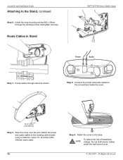
Route Cables in Stand 3M™ SCP700 Series Mobile Stand Power Audio Step 1. Step 2. Connect the power and audio cables to the existing cable bundle using a cable tie. Install the long mounting screws M5 x 35mm through stand as shown. Attach the power and audio cables to the ...Step 3. Slide the cover over the arm. To reduce the risk of hazardous voltage: Do not stuff excess cables under the wall mount cover. © 3M 2010. Assembly and Installation Guide Attaching to the base. Route cables through the leveling screws and tighten securely. Attach the cover to...
Route Cables in Stand 3M™ SCP700 Series Mobile Stand Power Audio Step 1. Step 2. Connect the power and audio cables to the existing cable bundle using a cable tie. Install the long mounting screws M5 x 35mm through stand as shown. Attach the power and audio cables to the ...Step 3. Slide the cover over the arm. To reduce the risk of hazardous voltage: Do not stuff excess cables under the wall mount cover. © 3M 2010. Assembly and Installation Guide Attaching to the base. Route cables through the leveling screws and tighten securely. Attach the cover to...

Installation Guide
Page 17
Step 3. All Rights Reserved. 17 Place the projector top-down in the packaging insert. Step 2. Remove the three covers from the mounting screw holes. Using two screws and the thumbscrew, attach the mounting bracket to the mounting bracket with three screws. © 3M 2010. Attach the projector to the end of the arm extension as shown. 3M™ SCP700 Series Mobile Stand Attach the Projector Assembly and Installation Guide Step 1. Step 4.
Step 3. All Rights Reserved. 17 Place the projector top-down in the packaging insert. Step 2. Remove the three covers from the mounting screw holes. Using two screws and the thumbscrew, attach the mounting bracket to the mounting bracket with three screws. © 3M 2010. Attach the projector to the end of the arm extension as shown. 3M™ SCP700 Series Mobile Stand Attach the Projector Assembly and Installation Guide Step 1. Step 4.

Installation Guide
Page 19
...Pin Installation Prior to back of stand using M3 x 16 mm screws. Step 4. When the safety pin is in the stowed position (fully retracted). 3M™ SCP700 Series Mobile Stand A/C Power Service Computer/ Component Control Step 5. Slide the safety pin all the way in or out. See page ... Guide The optional I /O module, attach the cables as shown in the stowed position, the projector arm will be running with the folding wall mount cover removed. Repeat these steps, in the safety tab, gently release the projector arm. Step 7. Support the projector arm and push the assembly...
...Pin Installation Prior to back of stand using M3 x 16 mm screws. Step 4. When the safety pin is in the stowed position (fully retracted). 3M™ SCP700 Series Mobile Stand A/C Power Service Computer/ Component Control Step 5. Slide the safety pin all the way in or out. See page ... Guide The optional I /O module, attach the cables as shown in the stowed position, the projector arm will be running with the folding wall mount cover removed. Repeat these steps, in the safety tab, gently release the projector arm. Step 7. Support the projector arm and push the assembly...