
Getting Started Guide
Page 2
... environmental standards. Ensuring that all operations. 3Com Corporation 350 Campus Drive Marlborough MA USA 01752-3064 Copyright © 2005, 3Com Corporation. No part of safely. IAll other countries. 3Com, the 3Com logo and SuperStack are associated. Ensuring that all waste conforms... rights only as translation, transformation, or adaptation) without written permission from sustainable, managed forests; Regulated Materials Statement 3Com products do not contain any time. Novell and NetWare are committed to remove or deface any portion of all operations...
... environmental standards. Ensuring that all operations. 3Com Corporation 350 Campus Drive Marlborough MA USA 01752-3064 Copyright © 2005, 3Com Corporation. No part of safely. IAll other countries. 3Com, the 3Com logo and SuperStack are associated. Ensuring that all waste conforms... rights only as translation, transformation, or adaptation) without written permission from sustainable, managed forests; Regulated Materials Statement 3Com products do not contain any time. Novell and NetWare are committed to remove or deface any portion of all operations...
Getting Started Guide
Page 3
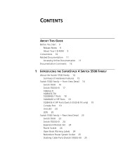
...TX/ 1000BASE-T Ports 18 1000BASE-X SFP Ports 19 100BASE-X SFP Ports (Switch 5500-EI FX only) 19 Console Port 19 Unit LED 20 LEDs 20 Switch 5500 Family - Rear View Detail 23 Switch 5500 23 Switch 5500G-EI 24 Expansion Module Slot 24 Power Socket 24 Open Book Warning ... 25 Stacking Cable Ports (Switch 5500G-EI) 25 CONTENTS ABOUT THIS GUIDE Before You Start 9 Release Notes 9 About Your CD-ROM 9 Conventions 10 Related Documentation 11 Accessing Online Documentation 11 Documentation Comments 12 1 INTRODUCING THE SUPERSTACK 4 SWITCH 5500 FAMILY About the Switch 5500 Family 14 Summary of Hardware...
...TX/ 1000BASE-T Ports 18 1000BASE-X SFP Ports 19 100BASE-X SFP Ports (Switch 5500-EI FX only) 19 Console Port 19 Unit LED 20 LEDs 20 Switch 5500 Family - Rear View Detail 23 Switch 5500 23 Switch 5500G-EI 24 Expansion Module Slot 24 Power Socket 24 Open Book Warning ... 25 Stacking Cable Ports (Switch 5500G-EI) 25 CONTENTS ABOUT THIS GUIDE Before You Start 9 Release Notes 9 About Your CD-ROM 9 Conventions 10 Related Documentation 11 Accessing Online Documentation 11 Documentation Comments 12 1 INTRODUCING THE SUPERSTACK 4 SWITCH 5500 FAMILY About the Switch 5500 Family 14 Summary of Hardware...

Getting Started Guide
Page 9
... the release notes differ from the information in this guide, follow the instructions in your Switch 5500. refer to "Related Documentation" on the 3Com World Wide Web site: http://www.3com.com/ ABOUT THIS GUIDE This guide provides all the information you need to install and ... the documents and CD-ROM that accompany your network. Before You Start This section contains information about the Switch 5500 - a powerful and easy-to-use 3Com® SuperStack® 4 Switch 5500 in Adobe Acrobat Reader Portable Document Format (PDF) or HTML on page 11 for installing and setting up...
... the release notes differ from the information in this guide, follow the instructions in your Switch 5500. refer to "Related Documentation" on the 3Com World Wide Web site: http://www.3com.com/ ABOUT THIS GUIDE This guide provides all the information you need to install and ... the documents and CD-ROM that accompany your network. Before You Start This section contains information about the Switch 5500 - a powerful and easy-to-use 3Com® SuperStack® 4 Switch 5500 in Adobe Acrobat Reader Portable Document Format (PDF) or HTML on page 11 for installing and setting up...

Getting Started Guide
Page 11
... This guide is also supplied under the Help button on the web interface. ■ SuperStack 4 Switch 5500 Configuration Guide This guide contains information on the features supported by your Switch and how they can be displayed automatically. 2 Select the Documentation section from the CD-... in PDF format on the CD-ROM that accompanies the Switch. ■ Release Notes These notes provide information about the web interface and command line interface that accompanies your Switch. ■ SuperStack 4 Switch 5500 Command Reference Guide This guide contains detailed information about the...
... This guide is also supplied under the Help button on the web interface. ■ SuperStack 4 Switch 5500 Configuration Guide This guide contains information on the features supported by your Switch and how they can be displayed automatically. 2 Select the Documentation section from the CD-... in PDF format on the CD-ROM that accompanies the Switch. ■ Release Notes These notes provide information about the web interface and command line interface that accompanies your Switch. ■ SuperStack 4 Switch 5500 Command Reference Guide This guide contains detailed information about the...

Getting Started Guide
Page 12
..., Document part number (on the CD-ROM. Your suggestions are very important to comments and questions about this document to 3Com at this e-mail address. Example: Part Number DUA1725-0AAA01 3Com SuperStack 4 Switch 5500 Getting Started Guide Page 21 Please note that we can only respond to us. 12 ABOUT THIS GUIDE Documentation Comments ■...
..., Document part number (on the CD-ROM. Your suggestions are very important to comments and questions about this document to 3Com at this e-mail address. Example: Part Number DUA1725-0AAA01 3Com SuperStack 4 Switch 5500 Getting Started Guide Page 21 Please note that we can only respond to us. 12 ABOUT THIS GUIDE Documentation Comments ■...

Getting Started Guide
Page 13
Rear View Detail ■ Default Settings It covers summary information about the Switch 5500 Family and how they can be used in your network. Front View Detail ■ Switch 5500 Family - 1 INTRODUCING THE SUPERSTACK 4 SWITCH 5500 FAMILY This chapter contains introductory information about the hardware and the following topics: ■ About the Switch 5500 Family ■ Switch 5500 Family -
Rear View Detail ■ Default Settings It covers summary information about the Switch 5500 Family and how they can be used in your network. Front View Detail ■ Switch 5500 Family - 1 INTRODUCING THE SUPERSTACK 4 SWITCH 5500 FAMILY This chapter contains introductory information about the hardware and the following topics: ■ About the Switch 5500 Family ■ Switch 5500 Family -
Getting Started Guide
Page 14
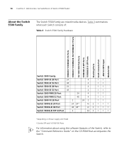
... Slot Switch 5500 Family Switch 5500-SI 28 Port 24 4 11 Switch 5500-SI 52 Port 48 4 11 Switch 5500-EI 28 Port 24 4 11 Switch 5500-EI 52 Port 48 4 11 Switch 5500 PWR 28 Port 24 4 11 Switch 5500 PWR 52 Port 48 4 11 Switch 5500 FX 28 Port 2 24 2 11 Switch 5500G-EI... 10/100/100 Ports For information about using the software features of the Switch, refer to the "Command Reference Guide" on the CD-ROM that accompanies the Switch. 14 CHAPTER 1: INTRODUCING THE SUPERSTACK 4 SWITCH 5500 FAMILY About the Switch 5500 Family The Switch 5500 Family are mixed media devices.
... Slot Switch 5500 Family Switch 5500-SI 28 Port 24 4 11 Switch 5500-SI 52 Port 48 4 11 Switch 5500-EI 28 Port 24 4 11 Switch 5500-EI 52 Port 48 4 11 Switch 5500 PWR 28 Port 24 4 11 Switch 5500 PWR 52 Port 48 4 11 Switch 5500 FX 28 Port 2 24 2 11 Switch 5500G-EI... 10/100/100 Ports For information about using the software features of the Switch, refer to the "Command Reference Guide" on the CD-ROM that accompanies the Switch. 14 CHAPTER 1: INTRODUCING THE SUPERSTACK 4 SWITCH 5500 FAMILY About the Switch 5500 Family The Switch 5500 Family are mixed media devices.
Getting Started Guide
Page 16
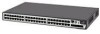
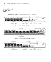
... LED RPS LED Mode LED 10/100BASE-TX Ports Figure 3 Switch 5500-EI 28-Port PWR - front view PWR LED 1000BASE-X Ports Port Status LEDs Console Port RPS LED 3CR17171-91 SuperStack 4 Switch 5500 PWR 28 Port Green=Status Yellow=Packet Red=PoE 10/100BASE-TX...Power LED 16 CHAPTER 1: INTRODUCING THE SUPERSTACK 4 SWITCH 5500 FAMILY Switch 5500 Family - front view Port Status LEDs Console Port RPS LED 10/100BASE-TX Ports 1000BASE-X Ports Unit LED Mode LED Power LED Figure 2 Switch 5500 SI and EI 52-Port - Front View Detail Switch 5500 Figure 1 Switch 5500 SI and EI 28-Port -
... LED RPS LED Mode LED 10/100BASE-TX Ports Figure 3 Switch 5500-EI 28-Port PWR - front view PWR LED 1000BASE-X Ports Port Status LEDs Console Port RPS LED 3CR17171-91 SuperStack 4 Switch 5500 PWR 28 Port Green=Status Yellow=Packet Red=PoE 10/100BASE-TX...Power LED 16 CHAPTER 1: INTRODUCING THE SUPERSTACK 4 SWITCH 5500 FAMILY Switch 5500 Family - front view Port Status LEDs Console Port RPS LED 10/100BASE-TX Ports 1000BASE-X Ports Unit LED Mode LED Power LED Figure 2 Switch 5500 SI and EI 52-Port - Front View Detail Switch 5500 Figure 1 Switch 5500 SI and EI 28-Port -
Getting Started Guide
Page 17
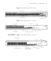
... view PWR LED 1000BASE-X Ports Port Status LEDs Speed Duplex Console Port RPS LED 3CR17181-91 SuperStack 4 Switch 5500-EI 28-Port FX 100Base-FX 1000Base-X 10/100/100BASE-T Green=Speed Yellow=Duplex RPS PWR... 7 19 8 20 9 21 10 22 11 23 12 24 21 22 23 Unit LED PWR LED RPS LED 3CR17251-91 SuperStack 4 Switch 5500G-EI 24-Port PWR Mode: 24 Console Unit 100% Green=Status 80% Yellow=Packet 60% Red=POE RPS MOD 40...LEDs Console Port Unit LED RPS LED Mode LED 3CR17172-91 SuperStack 4 Switch 5500 PWR 52 Port Green=Status Yellow=Packet Red=PoE 10/100BASE-TX Ports Figure...
... view PWR LED 1000BASE-X Ports Port Status LEDs Speed Duplex Console Port RPS LED 3CR17181-91 SuperStack 4 Switch 5500-EI 28-Port FX 100Base-FX 1000Base-X 10/100/100BASE-T Green=Speed Yellow=Duplex RPS PWR... 7 19 8 20 9 21 10 22 11 23 12 24 21 22 23 Unit LED PWR LED RPS LED 3CR17251-91 SuperStack 4 Switch 5500G-EI 24-Port PWR Mode: 24 Console Unit 100% Green=Status 80% Yellow=Packet 60% Red=POE RPS MOD 40...LEDs Console Port Unit LED RPS LED Mode LED 3CR17172-91 SuperStack 4 Switch 5500 PWR 52 Port Green=Status Yellow=Packet Red=PoE 10/100BASE-TX Ports Figure...

Getting Started Guide
Page 18
...to connect the unit to these sockets. They cannot be connected to a traditional PBX or public telephone network. 18 CHAPTER 1: INTRODUCING THE SUPERSTACK 4 SWITCH 5500 FAMILY Figure 7 Switch 5500G-EI (48 port) - Either shielded or unshielded data cables with shielded or unshielded jacks can be used as Auto MDIX (cross-...=1000Mbps Yellow=10/100Mbps D(Duplex):Green=Full Duplex Yellow=Half Duplex 1000Base-X 1000Base-X Power LED RPS LED 25/11 SD 3CR17259-91 SuperStack 4 Switch 5500G-EI SFP 24-Port 26/12 SD 27/23 SD 28/24 SD 10/100/1000Base-TX PWR RPS STK MOD 1000BASE-X ...
...to connect the unit to these sockets. They cannot be connected to a traditional PBX or public telephone network. 18 CHAPTER 1: INTRODUCING THE SUPERSTACK 4 SWITCH 5500 FAMILY Figure 7 Switch 5500G-EI (48 port) - Either shielded or unshielded data cables with shielded or unshielded jacks can be used as Auto MDIX (cross-...=1000Mbps Yellow=10/100Mbps D(Duplex):Green=Full Duplex Yellow=Half Duplex 1000Base-X 1000Base-X Power LED RPS LED 25/11 SD 3CR17259-91 SuperStack 4 Switch 5500G-EI SFP 24-Port 26/12 SD 27/23 SD 28/24 SD 10/100/1000Base-TX PWR RPS STK MOD 1000BASE-X ...

Getting Started Guide
Page 20
20 CHAPTER 1: INTRODUCING THE SUPERSTACK 4 SWITCH 5500 FAMILY Unit LED The Unit LED is a seven segment display visible ... Problems Indicated by LEDs" on using the LEDs for problem solving, see "Checking for Correct Operation of the Switch. Yellow flashing The port has failed POST. Yellow flashing The port has failed post. The Unit LED can be... blinking off for every packet received or transmitted. Yellow PoE error, no power supplied on the front of the Switch, and how to read their status according to unit being delivered. 10/100BASE-T/TX Ports LEDS Speed Green A...
20 CHAPTER 1: INTRODUCING THE SUPERSTACK 4 SWITCH 5500 FAMILY Unit LED The Unit LED is a seven segment display visible ... Problems Indicated by LEDs" on using the LEDs for problem solving, see "Checking for Correct Operation of the Switch. Yellow flashing The port has failed POST. Yellow flashing The port has failed post. The Unit LED can be... blinking off for every packet received or transmitted. Yellow PoE error, no power supplied on the front of the Switch, and how to read their status according to unit being delivered. 10/100BASE-T/TX Ports LEDS Speed Green A...

Getting Started Guide
Page 22
...download is OK. Loop cable is functioning without the loop connection. Off The Module is installed and operating normally. Module LED (Switch 5500G-EI only) Green The Module is not installed. Speed Green 10/100/1000 Port Speed and Activity, 1000 SFP Status ... connected. During software download, a clockwise cycling bar appears in progress. Green flashing 't' The Switch is over temperature and unit temperature is in progress. 22 CHAPTER 1: INTRODUCING THE SUPERSTACK 4 SWITCH 5500 FAMILY LED Color Indicates Unit LED Green Power on Self Test (POST) is critical. RPS ...
...download is OK. Loop cable is functioning without the loop connection. Off The Module is installed and operating normally. Module LED (Switch 5500G-EI only) Green The Module is not installed. Speed Green 10/100/1000 Port Speed and Activity, 1000 SFP Status ... connected. During software download, a clockwise cycling bar appears in progress. Green flashing 't' The Switch is over temperature and unit temperature is in progress. 22 CHAPTER 1: INTRODUCING THE SUPERSTACK 4 SWITCH 5500 FAMILY LED Color Indicates Unit LED Green Power on Self Test (POST) is critical. RPS ...

Getting Started Guide
Page 24
...or carrying out any supply voltage in the range 100-240 VAC. 24 CHAPTER 1: INTRODUCING THE SUPERSTACK 4 SWITCH 5500 FAMILY Switch 5500G-EI Power Socket Switch 5500G PoE PSU 24-Port NULL Figure 11 Switch 5500G-EI - rear view Stack LEDs Expansion Module Slot -52 - -55V;19.5A Redundant Power...=Stack Fault Stacking Cable Port (Up) Stacking Cable Port (Down) Expansion Module You can use this guide. VORSICHT:Bevor Sie Komponenten der Switch 5500-Baureihe installieren oder deinstallieren und bevor Sie Wartungsarbeiten ausführen, müssen Sie die in Appendix A of this slot to fit ...
...or carrying out any supply voltage in the range 100-240 VAC. 24 CHAPTER 1: INTRODUCING THE SUPERSTACK 4 SWITCH 5500 FAMILY Switch 5500G-EI Power Socket Switch 5500G PoE PSU 24-Port NULL Figure 11 Switch 5500G-EI - rear view Stack LEDs Expansion Module Slot -52 - -55V;19.5A Redundant Power...=Stack Fault Stacking Cable Port (Up) Stacking Cable Port (Down) Expansion Module You can use this guide. VORSICHT:Bevor Sie Komponenten der Switch 5500-Baureihe installieren oder deinstallieren und bevor Sie Wartungsarbeiten ausführen, müssen Sie die in Appendix A of this slot to fit ...

Getting Started Guide
Page 26
... Protocol (LACP) Spanning Tree Protocol Smart Auto-sensing Switch 5500 Family Enabled Auto-negotiated Auto-negotiated Enabled on the Switch 5500G-EI (when a PoE PSU is returned to the untagged Default VLAN (VLAN 1) with IEEE Std 802.1Q-1998 learning operational. 26 CHAPTER 1: INTRODUCING THE SUPERSTACK 4 SWITCH 5500 FAMILY Default Settings Table 6 shows the default settings...
... Protocol (LACP) Spanning Tree Protocol Smart Auto-sensing Switch 5500 Family Enabled Auto-negotiated Auto-negotiated Enabled on the Switch 5500G-EI (when a PoE PSU is returned to the untagged Default VLAN (VLAN 1) with IEEE Std 802.1Q-1998 learning operational. 26 CHAPTER 1: INTRODUCING THE SUPERSTACK 4 SWITCH 5500 FAMILY Default Settings Table 6 shows the default settings...

Getting Started Guide
Page 38
...Switch if the length is connected. The -48V DC power will take priority over the AC mains and will be powered by the RPS only. The earthing cable is only required if the Switch is connected to the Switch..., the circuit breaker in Appendix C on ) position and the Switch will power the Switch if it is Earthing Cable suitable....recommended cable length should not exceed 3 metres (9.84 feet). 38 CHAPTER 2: INSTALLING THE SWITCH Figure 14 RPS Connection to the closed (on page 139. Alternatively use the earthing ...
...Switch if the length is connected. The -48V DC power will take priority over the AC mains and will be powered by the RPS only. The earthing cable is only required if the Switch is connected to the Switch..., the circuit breaker in Appendix C on ) position and the Switch will power the Switch if it is Earthing Cable suitable....recommended cable length should not exceed 3 metres (9.84 feet). 38 CHAPTER 2: INSTALLING THE SWITCH Figure 14 RPS Connection to the closed (on page 139. Alternatively use the earthing ...

Getting Started Guide
Page 40
...can be positioned at each other end of SuperStack® units, the smaller units must use the self-adhesive rubber feet supplied. The Switch powers-up to get your power outlet. 40 CHAPTER 2: INSTALLING THE SWITCH The Switch 5500 supports 3Com 802.3af equipment. Placing Units On Top... of Each Other If the Switch units are mixing a variety of the power cord into your Switch 5500 powered-up the Switch. Power over Ethernet Configuration chapter in the marked ...
...can be positioned at each other end of SuperStack® units, the smaller units must use the self-adhesive rubber feet supplied. The Switch powers-up to get your power outlet. 40 CHAPTER 2: INSTALLING THE SWITCH The Switch 5500 supports 3Com 802.3af equipment. Placing Units On Top... of Each Other If the Switch units are mixing a variety of the power cord into your Switch 5500 powered-up the Switch. Power over Ethernet Configuration chapter in the marked ...

Getting Started Guide
Page 54
...to allocate IP information, or ■ flexibility is deployed onto a different subnet, it will automatically reconfigure itself with the Switch or on the 3Com Web site. 54 CHAPTER 3: SETTING UP FOR MANAGEMENT be allocated to the Configuration Guide on page 61. For detailed ... your DHCP/BootP server. For a detailed description of you can begin management. Refer to the "SuperStack 4 Switch 5500 Command Reference Guide" on page 50. Preparing for Once your Switch's initial set up is supplied with an appropriate IP address, instead of how automatic IP configuration operates...
...to allocate IP information, or ■ flexibility is deployed onto a different subnet, it will automatically reconfigure itself with the Switch or on the 3Com Web site. 54 CHAPTER 3: SETTING UP FOR MANAGEMENT be allocated to the Configuration Guide on page 61. For detailed ... your DHCP/BootP server. For a detailed description of you can begin management. Refer to the "SuperStack 4 Switch 5500 Command Reference Guide" on page 50. Preparing for Once your Switch's initial set up is supplied with an appropriate IP address, instead of how automatic IP configuration operates...

Getting Started Guide
Page 68
... as default. The default write community string is public. You can access and change the default passwords, you intend to manage the Switch using the command line interface system management snmp community command - These default users are in snmp menu in Table 18. To change ...no security - the user can access and change any manageable parameters manager manager - The Switch has three default user names, and each user name has a different password and level of the "SuperStack 4 Switch Command Reference Guide" for the users defined on as possible, even if you do this ...
... as default. The default write community string is public. You can access and change the default passwords, you intend to manage the Switch using the command line interface system management snmp community command - These default users are in snmp menu in Table 18. To change ...no security - the user can access and change any manageable parameters manager manager - The Switch has three default user names, and each user name has a different password and level of the "SuperStack 4 Switch Command Reference Guide" for the users defined on as possible, even if you do this ...

Getting Started Guide
Page 69
... admin user in the User View. Configuration Conversion Utility The 3Com Switch 5500 Family Configuration Conversion Utility (CCU) enables you to login and carry out initial Switch setup. To set a password for a number of 3Com SuperStack II and SuperStack 3 devices to the Configuration Guide that accompanies your Switch. For information on the CD that is supplied with your...
... admin user in the User View. Configuration Conversion Utility The 3Com Switch 5500 Family Configuration Conversion Utility (CCU) enables you to login and carry out initial Switch setup. To set a password for a number of 3Com SuperStack II and SuperStack 3 devices to the Configuration Guide that accompanies your Switch. For information on the CD that is supplied with your...
Getting Started Guide
Page 72
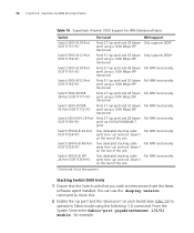
... enter fabric-port gigabitethernet 1/0/51 enable, for XRN Distributed Fabric Switch Port used XRN support Switch 5500-SI 28-Port (3CR17151-91) Ports 27 (up port) and 28 (down Only supports DDM* port) using a 1000 Mbps SFP transceiver Switch 5500-SI 52-Port (3CR17152-91) Ports 51 (up port) and ... the 'up ' and one 'down ') on the rear of the unit. 72 CHAPTER 4: CREATING AN XRN STACKING FABRIC Table 19 SuperStack 4 Switch 5500 Support for example. Switch 5500G-EI 48-Port Two dedicated stacking cable Full XRN functionality (3CR17255-91) ports (one 'up ' and one 'down') on the...
... enter fabric-port gigabitethernet 1/0/51 enable, for XRN Distributed Fabric Switch Port used XRN support Switch 5500-SI 28-Port (3CR17151-91) Ports 27 (up port) and 28 (down Only supports DDM* port) using a 1000 Mbps SFP transceiver Switch 5500-SI 52-Port (3CR17152-91) Ports 51 (up port) and ... the 'up ' and one 'down ') on the rear of the unit. 72 CHAPTER 4: CREATING AN XRN STACKING FABRIC Table 19 SuperStack 4 Switch 5500 Support for example. Switch 5500G-EI 48-Port Two dedicated stacking cable Full XRN functionality (3CR17255-91) ports (one 'up ' and one 'down') on the...
