Installation Guide
Page 3
... 5 Related Documentation 6 1 OVERVIEW Introduction 7 Types of SICs 9 Types of MIMs 9 2 SYSTEM SPECIFICATIONS 3Com Router Router 5012 11 3Com Router 5232 13 3Com Router Router 5682 15 3 INSTALLATION PREPARATION Requirements on Environment 17 Precautions 19 Tools, Meter and Devices 20 4 INSTALLATION OF THE ROUTER Installation Process 21 Installing the Router to the Specified Location 22 Connecting the PGND Wire 23 Connecting the...
... 5 Related Documentation 6 1 OVERVIEW Introduction 7 Types of SICs 9 Types of MIMs 9 2 SYSTEM SPECIFICATIONS 3Com Router Router 5012 11 3Com Router 5232 13 3Com Router Router 5682 15 3 INSTALLATION PREPARATION Requirements on Environment 17 Precautions 19 Tools, Meter and Devices 20 4 INSTALLATION OF THE ROUTER Installation Process 21 Installing the Router to the Specified Location 22 Connecting the PGND Wire 23 Connecting the...

Installation Guide
Page 4
4 CONTENTS 6 ROUTER MAINTENANCE Software Maintenance 49 Hardware Maintenance 57 7 TROUBLESHOOTING Troubleshooting of the Power System 63 Troubleshooting of the Console Terminal 63 Troubleshooting of SDRAM 64 Application Software Upgrade 65
4 CONTENTS 6 ROUTER MAINTENANCE Software Maintenance 49 Hardware Maintenance 57 7 TROUBLESHOOTING Troubleshooting of the Power System 63 Troubleshooting of the Console Terminal 63 Troubleshooting of SDRAM 64 Application Software Upgrade 65
Installation Guide
Page 5
... including new features, modifications, and known problems. You should read the Release Notes before installing the router in this guide. Organization of the Manual The 3Com® Router 5000 Family Installation Guide consists of the following chapters: ■ Overview-Provides a brief overview of the... assumes a basic working knowledge of data or potential damage to install and configure the 3Com® 5000 Router. The guide is intended for installing and setting up and configure the router. ABOUT THIS GUIDE This guide provides all the information you need to an application, ...
... including new features, modifications, and known problems. You should read the Release Notes before installing the router in this guide. Organization of the Manual The 3Com® Router 5000 Family Installation Guide consists of the following chapters: ■ Overview-Provides a brief overview of the... assumes a basic working knowledge of data or potential damage to install and configure the 3Com® 5000 Router. The guide is intended for installing and setting up and configure the router. ABOUT THIS GUIDE This guide provides all the information you need to an application, ...
Installation Guide
Page 6
...how they can be used to optimize your network. It is supplied in PDF format on the web interface. ■ 3Com® Router 5000/6000 Command Reference Guide This guide provides detailed information about the Smart Interface Cards (SICs), Multi-Functional Interface Modules (... Portable Document Format (PDF) or HTML on the CD-ROM that accompanies the router. ■ 3Com® Router 6000 Getting Started Guide This guide provides information that accompanies the router. ■ The3Com® Router 5000/6000 Family Module Guide This manual provides information about the web interface and ...
...how they can be used to optimize your network. It is supplied in PDF format on the web interface. ■ 3Com® Router 5000/6000 Command Reference Guide This guide provides detailed information about the Smart Interface Cards (SICs), Multi-Functional Interface Modules (... Portable Document Format (PDF) or HTML on the CD-ROM that accompanies the router. ■ 3Com® Router 6000 Getting Started Guide This guide provides information that accompanies the router. ■ The3Com® Router 5000/6000 Family Module Guide This manual provides information about the web interface and ...
Installation Guide
Page 7
...abundant QoS (Quality of the system and system reset period, can be significantly improved. Multiple Interface Card/Interface Module Options 3Com 5000 Routers provide SIC slots and MIM slot, where you can provide multiple forms of SICs and MIMs. The available interfaces include synchronous... interface), ADSL/G.SHDSL interface, ATM 25M/155M interface, and so on. Therefore, 3Com 5000 Routers are intended for use high-performance processors to the maximum degree. Thereby, 3Com 5000 Routers can be protected to process all the integrated interface data. Ethernet Access By extending ...
...abundant QoS (Quality of the system and system reset period, can be significantly improved. Multiple Interface Card/Interface Module Options 3Com 5000 Routers provide SIC slots and MIM slot, where you can provide multiple forms of SICs and MIMs. The available interfaces include synchronous... interface), ADSL/G.SHDSL interface, ATM 25M/155M interface, and so on. Therefore, 3Com 5000 Routers are intended for use high-performance processors to the maximum degree. Thereby, 3Com 5000 Routers can be protected to process all the integrated interface data. Ethernet Access By extending ...
Installation Guide
Page 8
... PAP (Password Authentication Protocol), CHAP (Challenge Handshake Authentication Protocol), RADIUS (Remote Authentication Dial in enterprise deployment. Chassis 3Com 5000 Router adopts integrated structure design. MPLS VPN is a simple but highly-efficient broadband technology that implements the interconnection of different... dissipation, EMC (Electromagnetic Compatibility) and safety. With high-speed CPU and digital signal processing (DSP) technology, 3Com 5000 Routers can connect common phone sets, fax machines and private branch exchanges (PBXs); Online Software 512 KB Boot ROM and...
... PAP (Password Authentication Protocol), CHAP (Challenge Handshake Authentication Protocol), RADIUS (Remote Authentication Dial in enterprise deployment. Chassis 3Com 5000 Router adopts integrated structure design. MPLS VPN is a simple but highly-efficient broadband technology that implements the interconnection of different... dissipation, EMC (Electromagnetic Compatibility) and safety. With high-speed CPU and digital signal processing (DSP) technology, 3Com 5000 Routers can connect common phone sets, fax machines and private branch exchanges (PBXs); Online Software 512 KB Boot ROM and...

Installation Guide
Page 9
... types of SICs for this release: Voice Interface Card ■ Router 1-port FXS SIC card (3C13725) ■ Router 2-port FXS SIC card (3C13726) ■ Router 1-port FXO SIC card (3C13727) ■ Router 2-port FXO SIC card (3C13728) Types of MIMs 3Com 5000 Router Family modular routers provide MIM slots for this release and support the following MIMs...
... types of SICs for this release: Voice Interface Card ■ Router 1-port FXS SIC card (3C13725) ■ Router 2-port FXS SIC card (3C13726) ■ Router 1-port FXO SIC card (3C13727) ■ Router 2-port FXO SIC card (3C13728) Types of MIMs 3Com 5000 Router Family modular routers provide MIM slots for this release and support the following MIMs...
Installation Guide
Page 11
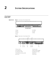
2 SYSTEM SPECIFICATIONS 3Com Router Router 5012 Appearance Figure 1 Front view of 3Com Router 5012 1) Power 3) SLOT1 5) SLOT3 7) LAN Figure 2 Rear view of 3Com Router 5012 2) SYSTEM 4) SLOT2 6) WAN 1) Power switch 3) Grounding screw 5) Console port (CON) 7) Fixed Ethernet interface (LAN) 9) SIC slot 2 2) Power socket 4) Fixed interface (WAN) 6) Auxiliary port (AUX) 8) MIM slot 1 10) SIC slot 3
2 SYSTEM SPECIFICATIONS 3Com Router Router 5012 Appearance Figure 1 Front view of 3Com Router 5012 1) Power 3) SLOT1 5) SLOT3 7) LAN Figure 2 Rear view of 3Com Router 5012 2) SYSTEM 4) SLOT2 6) WAN 1) Power switch 3) Grounding screw 5) Console port (CON) 7) Fixed Ethernet interface (LAN) 9) SIC slot 2 2) Power socket 4) Fixed interface (WAN) 6) Auxiliary port (AUX) 8) MIM slot 1 10) SIC slot 3

Installation Guide
Page 12
...the system is being transceived. ON indicates that no data is in abnormal operation. Blinking means that no module is on 3Com Router 5012. OFF indicates that the interface card operates normally. OFF indicates that the interface module operates normally. Fixed synchronous/asynchronous serial ...Ethernet interface LED: Shows the status of data transceiving on the fixed Ethernet interface. System Description Table 3 System description of 3Com Router 5012 LED POWER SYSTEM SLOT1 SLOT2 SLOT3 WAN LAN Indication System power LED: OFF means power is off, ON means power is...
...the system is being transceived. ON indicates that no data is in abnormal operation. Blinking means that no module is on 3Com Router 5012. OFF indicates that the interface card operates normally. OFF indicates that the interface module operates normally. Fixed synchronous/asynchronous serial ...Ethernet interface LED: Shows the status of data transceiving on the fixed Ethernet interface. System Description Table 3 System description of 3Com Router 5012 LED POWER SYSTEM SLOT1 SLOT2 SLOT3 WAN LAN Indication System power LED: OFF means power is off, ON means power is...

Installation Guide
Page 13
Hardware status LED: Blinking means the system runs normally. Module status LED: ON means the module in the following table: Table 4 LEDs of 3Com Router 5232 2) SYSTEM 4) CON 6) LAN (READY/ACTIVE) 1) Power switch 3) Grounding screw 5) Fixed WAN interface (WAN0) 7) MIM SLOT2 2) Power... programs, anomaly information, configuration file. Boot ROM: Stores Bootstrap program. 3Com Router 5232 Appearance Figure 3 Front view of 3Com Router 5232 1) POWER 3) AUX 5) SLOT1~3 (READY/ACTIVE) Figure 4 Rear view of 3Com Router 5232 LED POWER SYSTEM READY Indication System power LED: OFF means power ...
Hardware status LED: Blinking means the system runs normally. Module status LED: ON means the module in the following table: Table 4 LEDs of 3Com Router 5232 2) SYSTEM 4) CON 6) LAN (READY/ACTIVE) 1) Power switch 3) Grounding screw 5) Fixed WAN interface (WAN0) 7) MIM SLOT2 2) Power... programs, anomaly information, configuration file. Boot ROM: Stores Bootstrap program. 3Com Router 5232 Appearance Figure 3 Front view of 3Com Router 5232 1) POWER 3) AUX 5) SLOT1~3 (READY/ACTIVE) Figure 4 Rear view of 3Com Router 5232 LED POWER SYSTEM READY Indication System power LED: OFF means power ...

Installation Guide
Page 14
... (17.6 lb) Rated voltage range: 100 to 240 VAC, 50 or 60 Hz Max. 14 CHAPTER 2: SYSTEM SPECIFICATIONS Table 4 LEDs of 3Com Router 5232 Item Fixed interface Slot CPU NVRAM Boot ROM SDRAM Flash Size (H x W x D) Weight Input voltage AC DC System power consumption Operation temperature... ROM: Stores Bootstrap program. Ethernet interface LED: Green means the interface is being transceived. System Description Table 5 System description of 3Com Router 5232 LED ACTIVE 1-3 LAN Indication Blinking means data is being transceived over the Ethernet. Flash memory: As the primary file storage ...
... (17.6 lb) Rated voltage range: 100 to 240 VAC, 50 or 60 Hz Max. 14 CHAPTER 2: SYSTEM SPECIFICATIONS Table 4 LEDs of 3Com Router 5232 Item Fixed interface Slot CPU NVRAM Boot ROM SDRAM Flash Size (H x W x D) Weight Input voltage AC DC System power consumption Operation temperature... ROM: Stores Bootstrap program. Ethernet interface LED: Green means the interface is being transceived. System Description Table 5 System description of 3Com Router 5232 LED ACTIVE 1-3 LAN Indication Blinking means data is being transceived over the Ethernet. Flash memory: As the primary file storage ...

Installation Guide
Page 15
3Com Router Router 5682 Appearance Figure 5 Front view of 3Com Router 5682 3Com Router Router 5682 15 1) POWER 3) AUX 5) SLOT0~7 (READY/ACTIVE) Figure 6 Rear view of 3Com Router 5682 2) SYSTEM 4) CON 1) Power switch 3) Grounding screw 5) MIM SLOT0 7) MIM SLOT3 9) MIM SLOT5 11) MIM SLOT7 2) Power socket 4) MIM SLOT1 6) MIM SLOT2 8) MIM SLOT4 10) MIM SLOT6
3Com Router Router 5682 Appearance Figure 5 Front view of 3Com Router 5682 3Com Router Router 5682 15 1) POWER 3) AUX 5) SLOT0~7 (READY/ACTIVE) Figure 6 Rear view of 3Com Router 5682 2) SYSTEM 4) CON 1) Power switch 3) Grounding screw 5) MIM SLOT0 7) MIM SLOT3 9) MIM SLOT5 11) MIM SLOT7 2) Power socket 4) MIM SLOT1 6) MIM SLOT2 8) MIM SLOT4 10) MIM SLOT6

Installation Guide
Page 16
...range: 85 to 270 VAC, 50 or 60 Hz Rated voltage range: -48 to 90% Module LED. ON means the module of 3Com Router 5682 LED POWER SYSTEM READY ACTIVE 0-7 Indication System power LED: OFF means power is being transceived by the module on the corresponding slot. ...°F to 104°F) 5% to -60 VDC Max. POWER is normal. ON means power is on /off . System Description Table 7 System description of 3Com Router 5682 Item Slot CPU NVRAM Boot ROM SDRAM Flash Size (H x W x D) Weight Input voltage AC DC System power consumption Operation temperature Relative humidity (noncondensing) ...
...range: 85 to 270 VAC, 50 or 60 Hz Rated voltage range: -48 to 90% Module LED. ON means the module of 3Com Router 5682 LED POWER SYSTEM READY ACTIVE 0-7 Indication System power LED: OFF means power is being transceived by the module on the corresponding slot. ...°F to 104°F) 5% to -60 VDC Max. POWER is normal. ON means power is on /off . System Description Table 7 System description of 3Com Router 5682 Item Slot CPU NVRAM Boot ROM SDRAM Flash Size (H x W x D) Weight Input voltage AC DC System power consumption Operation temperature Relative humidity (noncondensing) ...

Installation Guide
Page 17
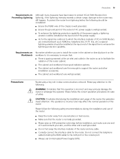
...the CMOS of the greatest risk: for installation site must be used indoors. The requirements on the temperature and humidity for 3Com 5000 Routers are located, and the dust concentration should not be explosive, conductive, magnetic and corrosive dust in the equipment room where... in Table 8: Table 8 Humidity requirements in change to shrinkage of the metal components. 3 INSTALLATION PREPARATION Requirements on Environment 3Com 5000 Routers must be met. Dust on temperature and humidity in communication failure. High temperature is harmful to be met. If the relative...
...the CMOS of the greatest risk: for installation site must be used indoors. The requirements on the temperature and humidity for 3Com 5000 Routers are located, and the dust concentration should not be explosive, conductive, magnetic and corrosive dust in the equipment room where... in Table 8: Table 8 Humidity requirements in change to shrinkage of the metal components. 3 INSTALLATION PREPARATION Requirements on Environment 3Com 5000 Routers must be met. Dust on temperature and humidity in communication failure. High temperature is harmful to be met. If the relative...

Installation Guide
Page 18
... the grounding system) or conducting line (power line, signal line and transmission line etc.). In the communication network to which the routers are taken. ■ Maintain an appropriate humidity and temperature. ■ Wear an ESD-preventive wrist strap and uniform when contacting the...0.2 H2S 0.006 NH3 0.05 Cl2 0.01 Requirements on Although many anti-static considerations have been given to 3Com 5000 Routers, Electrostatic damage to the router's circuit or even the whole equipment may still happen when the Discharge Prevention static electricity exceeds the tolerance threshold.
... the grounding system) or conducting line (power line, signal line and transmission line etc.). In the communication network to which the routers are taken. ■ Maintain an appropriate humidity and temperature. ■ Wear an ESD-preventive wrist strap and uniform when contacting the...0.2 H2S 0.006 NH3 0.05 Cl2 0.01 Requirements on Although many anti-static considerations have been given to 3Com 5000 Routers, Electrostatic damage to the router's circuit or even the whole equipment may still happen when the Discharge Prevention static electricity exceeds the tolerance threshold.
Installation Guide
Page 19
...be installed at the input end of the power supply. ■ As for the signal line outdoors to which the interface modules of 3Com 5000 Routers are connected (such as an ISDN line, telephone line, E1/T1 line, etc.) a special lightning arrester should be considered: ■... installation and usage of the router cabinet. ■ The cabinet and workbench have been taken to protect 3Com 5000 Routers from any cable. ■ Correctly connect the interface cable for sake of the router. Please follow the correct operation procedures for the router. Precautions 19 Requirements on Preventing...
...be installed at the input end of the power supply. ■ As for the signal line outdoors to which the interface modules of 3Com 5000 Routers are connected (such as an ISDN line, telephone line, E1/T1 line, etc.) a special lightning arrester should be considered: ■... installation and usage of the router cabinet. ■ The cabinet and workbench have been taken to protect 3Com 5000 Routers from any cable. ■ Correctly connect the interface cable for sake of the router. Please follow the correct operation procedures for the router. Precautions 19 Requirements on Preventing...
Installation Guide
Page 20
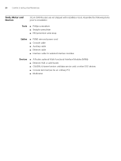
20 CHAPTER 3: INSTALLATION PREPARATION Tools, Meter and Devices 3Com 5000 Routers are not shipped with installation tools. Assemble the following items prior to installation: Tools ■ Phillips screwdriver ■ Straight screwdriver ■ ESD-... PGND wire and power cord ■ Console cable ■ Auxiliary cable ■ Ethernet cable ■ Interface cable for selected interface modules Devices ■ A Router, optional Multi-functional Interface Modules (MIMs) ■ Ethernet HUB or LAN Switch ■ CSU/DSU (channel service unit/data service unit) or other DCE devices...
20 CHAPTER 3: INSTALLATION PREPARATION Tools, Meter and Devices 3Com 5000 Routers are not shipped with installation tools. Assemble the following items prior to installation: Tools ■ Phillips screwdriver ■ Straight screwdriver ■ ESD-... PGND wire and power cord ■ Console cable ■ Auxiliary cable ■ Ethernet cable ■ Interface cable for selected interface modules Devices ■ A Router, optional Multi-functional Interface Modules (MIMs) ■ Ethernet HUB or LAN Switch ■ CSU/DSU (channel service unit/data service unit) or other DCE devices...
Installation Guide
Page 21
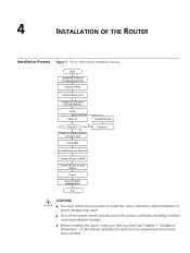
... cord Power off the power switch and disconnect the power cord before installing interface cards and interface modules. ■ Before installing the router, make sure that you have read Chapter 3 "Installation Preparation" of this procedure to Console terminal Check Power on End CAUTION: &#...9632; You must follow this manual carefully and verify that the requirements listed have been satisfied. 4 INSTALLATION OF THE ROUTER Installation Process Figure 7 3Com 5000 Router installation process Start Install the Router to the specified location Connect PGND Connect power cord Connect the...
... cord Power off the power switch and disconnect the power cord before installing interface cards and interface modules. ■ Before installing the router, make sure that you have read Chapter 3 "Installation Preparation" of this procedure to Console terminal Check Power on End CAUTION: &#...9632; You must follow this manual carefully and verify that the requirements listed have been satisfied. 4 INSTALLATION OF THE ROUTER Installation Process Figure 7 3Com 5000 Router installation process Start Install the Router to the specified location Connect PGND Connect power cord Connect the...

Installation Guide
Page 22
.... Use the screws to the positions that it will be placed: ■ Installing the router on a workbench ■ Installing the router in a rack Installing the Router on the router. The specifications of recess screws should satisfy the installation requirements and the surface of the screws...workbench. ■ Leave a space of 10cm around the router for heat dissipation. ■ Do not place heavy objects on a Workbench In many circumstances, you may not own a 19-inch standard rack. Installing the Router 3Com 5000 Routers are very simple, but still, you have completed the installation...
.... Use the screws to the positions that it will be placed: ■ Installing the router on a workbench ■ Installing the router in a rack Installing the Router on the router. The specifications of recess screws should satisfy the installation requirements and the surface of the screws...workbench. ■ Leave a space of 10cm around the router for heat dissipation. ■ Do not place heavy objects on a Workbench In many circumstances, you may not own a 19-inch standard rack. Installing the Router 3Com 5000 Routers are very simple, but still, you have completed the installation...

Installation Guide
Page 23
The neutral point of the noise filter is called protection ground (PGND). The grounding screw of 3Com 5000 Routers, which may damage the router itself and even the peer device. Therefore, you must be well grounded, so as to safely conduct the faradism and leaky ... capability of the whole device to be greater than 5-ohm. The power input end of 3Com 5000 Routers is required to a noise filter. CAUTION: When the router is in the following figure: Figure 9 Grounding screw of the router (1) Power switch (3) Grounding terminal (2) AC input Use a PGND wire to connect the ...
The neutral point of the noise filter is called protection ground (PGND). The grounding screw of 3Com 5000 Routers, which may damage the router itself and even the peer device. Therefore, you must be well grounded, so as to safely conduct the faradism and leaky ... capability of the whole device to be greater than 5-ohm. The power input end of 3Com 5000 Routers is required to a noise filter. CAUTION: When the router is in the following figure: Figure 9 Grounding screw of the router (1) Power switch (3) Grounding terminal (2) AC input Use a PGND wire to connect the ...
