Getting Started Guide
Page 9
...-ROM that enable you may find useful: ■ Documentation accompanying the Advanced Redundant Power System. ■ Documentation accompanying the Expansion Modules. ■ Documentation accompanying 3Com Network Supervisor. It is supplied in HTML format on the CD-ROM that accompanies the Switch. ■ Management Interface Reference Guide This guide provides detailed information about the current...
...-ROM that enable you may find useful: ■ Documentation accompanying the Advanced Redundant Power System. ■ Documentation accompanying the Expansion Modules. ■ Documentation accompanying 3Com Network Supervisor. It is supplied in HTML format on the CD-ROM that accompanies the Switch. ■ Management Interface Reference Guide This guide provides detailed information about the current...

Getting Started Guide
Page 19
... System Socket to connect a SuperStack 3 Advanced Redundant Power System (RPS) to any supply voltage in the range 90-240 VAC. Redundant Power To protect against internal power supply failure, you can use this information for fault reporting purposes. See "Connecting a Redundant Power System" on page 27. Power Socket The Switch automatically adjusts its power setting to the Switch. Figure 7 Switch 4924 - rear view...
... System Socket to connect a SuperStack 3 Advanced Redundant Power System (RPS) to any supply voltage in the range 90-240 VAC. Redundant Power To protect against internal power supply failure, you can use this information for fault reporting purposes. See "Connecting a Redundant Power System" on page 27. Power Socket The Switch automatically adjusts its power setting to the Switch. Figure 7 Switch 4924 - rear view...

Getting Started Guide
Page 27
... a list of suggested solutions. Switch 1 Plug the power cord into your Switch if a power supply failure occurs. The Switch is powered-up and operating normally. Connecting a You can connect a SuperStack 3 Advanced Redundant Power System to make sure that your Switch powered-up and runs through its Power On Self Test (POST) because of the power cord into the power socket at the rear of...
... a list of suggested solutions. Switch 1 Plug the power cord into your Switch if a power supply failure occurs. The Switch is powered-up and operating normally. Connecting a You can connect a SuperStack 3 Advanced Redundant Power System to make sure that your Switch powered-up and runs through its Power On Self Test (POST) because of the power cord into the power socket at the rear of...

Getting Started Guide
Page 54
... or straight) Auto-negotiation problems will be indicated on the Switch indicate a problem, refer to the supply outlet. On powering-up ■ The quality of cable is disabled and incorrect cables are powered-up , the Power/Self Test LED lights yellow The Switch unit has failed its Power On Self Test (POST) because of suggested solutions below...
... or straight) Auto-negotiation problems will be indicated on the Switch indicate a problem, refer to the supply outlet. On powering-up ■ The quality of cable is disabled and incorrect cables are powered-up , the Power/Self Test LED lights yellow The Switch unit has failed its Power On Self Test (POST) because of suggested solutions below...
Getting Started Guide
Page 55
... ■ Web interface - If more detailed information about RMON, refer to "Chapter 7: Status Monitoring and Statistics" in the Switch Implementation Guide supplied in the Switch, a warning message will be tightened. Should one fan fails in PDF format on to the CLI. For more than one ...fan failure occur in the Switch, a warning message will not power up . An indication of fan failure is provided through the Device Summary...
... ■ Web interface - If more detailed information about RMON, refer to "Chapter 7: Status Monitoring and Statistics" in the Switch Implementation Guide supplied in the Switch, a warning message will be tightened. Should one fan fails in PDF format on to the CLI. For more than one ...fan failure occur in the Switch, a warning message will not power up . An indication of fan failure is provided through the Device Summary...

Getting Started Guide
Page 56
...remove and reconnect the AC mains supply. Error message indicating that the GBIC transceiver is invalid The Switch has identified that : ■ The air vents are not obstructed. 3 Power cycle the unit. Unit fails, no AC main supply, remove and reconnect the DC RPS supply. 4 If another fan failure ... unit has no AC mains supply, remove and reconnect the DC RPS supply. 2 Check the command line interface (system summary command) to 3Com. If the problem persists, contact 3Com Technical Support. If the unit has no SNMP fan failure message is received 1 Power cycle the unit. Error message...
...remove and reconnect the AC mains supply. Error message indicating that the GBIC transceiver is invalid The Switch has identified that : ■ The air vents are not obstructed. 3 Power cycle the unit. Unit fails, no AC main supply, remove and reconnect the DC RPS supply. 4 If another fan failure ... unit has no AC mains supply, remove and reconnect the DC RPS supply. 2 Check the command line interface (system summary command) to 3Com. If the problem persists, contact 3Com Technical Support. If the unit has no SNMP fan failure message is received 1 Power cycle the unit. Error message...
Getting Started Guide
Page 60
WARNING: If installing the Switch in a stack with safety standards. WARNING: Connect the unit to an earthed power supply to the unit and not the wall plug) must comply with an EN60320/IEC320 appliance inlet. and Canada United Kingdom only Europe only: Denmark.... WARNING: The appliance coupler (the connector to ensure compliance with SuperStack 3 units that are narrower than the Switch, the Switch unit must be UL-approved and CSA certified. ■ The minimum specification for mating with SEV/ASE 1011. WARNING: Power Cord Set: This must be approved for the country where it ...
WARNING: If installing the Switch in a stack with safety standards. WARNING: Connect the unit to an earthed power supply to the unit and not the wall plug) must comply with an EN60320/IEC320 appliance inlet. and Canada United Kingdom only Europe only: Denmark.... WARNING: The appliance coupler (the connector to ensure compliance with SuperStack 3 units that are narrower than the Switch, the Switch unit must be UL-approved and CSA certified. ■ The minimum specification for mating with SEV/ASE 1011. WARNING: Power Cord Set: This must be approved for the country where it ...

Getting Started Guide
Page 61
... the console port of IT type, this unit must be powered by tightening all screws with shielded or unshielded jacks can only remove power from the unit by disconnecting the power cord from IT† supplies. WARNING: The switch should only be used to suspend the switch from under a table or desk, or attach it to...
... the console port of IT type, this unit must be powered by tightening all screws with shielded or unshielded jacks can only remove power from the unit by disconnecting the power cord from IT† supplies. WARNING: The switch should only be used to suspend the switch from under a table or desk, or attach it to...

Getting Started Guide
Page 74
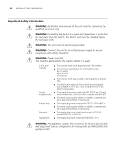
74 APPENDIX C: TECHNICAL SPECIFICATIONS Heat Dissipation Power Supply AC Line Frequency Input Voltage Options Current Rating Switch 4900:1050 BTU/hour maximum Switch 4900 SX: 560 BTU/hour maximum Switch 4924: 870 BTU/hour maximum Switch 4950: 685 BTU/hour maximum 50/60 Hz 90-240 VAC Switch 4900: 4 A (amps) (maximum) Switch 4900 SX: 3 A (amps) (maximum) Switch 4924 and 4950: 4.5 A (amps) (maximum)
74 APPENDIX C: TECHNICAL SPECIFICATIONS Heat Dissipation Power Supply AC Line Frequency Input Voltage Options Current Rating Switch 4900:1050 BTU/hour maximum Switch 4900 SX: 560 BTU/hour maximum Switch 4924: 870 BTU/hour maximum Switch 4950: 685 BTU/hour maximum 50/60 Hz 90-240 VAC Switch 4900: 4 A (amps) (maximum) Switch 4900 SX: 3 A (amps) (maximum) Switch 4924 and 4950: 4.5 A (amps) (maximum)

