Getting Started Guide
Page 3
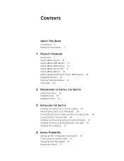
... 5 Related Documentation 5 1 PRODUCT OVERVIEW Introduction 7 Switch 4800G 24-Port 8 Switch 4800G PWR 48-Port 11 Switch 4800G PWR 24-Port 13 Switch 4800G 24-Port SFP 17 Switch 4800G 48-Port 18 System Specifications of the Switch 4800G Series 22 Pluggable Modules 22 Optional Interface Modules 23 CX4 Cable 24 2 PREPARATING TO INSTALL THE SWITCH Safety Precautions 25 Installation Site 25 Installation Tools 27 3 INSTALLING THE SWITCH Installing the Switch into a 19-Inch Cabinet 29 Mounting...
... 5 Related Documentation 5 1 PRODUCT OVERVIEW Introduction 7 Switch 4800G 24-Port 8 Switch 4800G PWR 48-Port 11 Switch 4800G PWR 24-Port 13 Switch 4800G 24-Port SFP 17 Switch 4800G 48-Port 18 System Specifications of the Switch 4800G Series 22 Pluggable Modules 22 Optional Interface Modules 23 CX4 Cable 24 2 PREPARATING TO INSTALL THE SWITCH Safety Precautions 25 Installation Site 25 Installation Tools 27 3 INSTALLING THE SWITCH Installing the Switch into a 19-Inch Cabinet 29 Mounting...
Getting Started Guide
Page 7
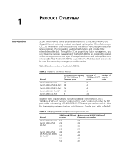
... extended module slots. 1 PRODUCT OVERVIEW Introduction 3Com Switch 4800G Family (hereinafter referred to as the Switch 4800G) are designed to operate at a time. Table 2 Models of the Switch 4800G Model Switch 4800G 24-Port Switch 4800G PWR 48-Port Switch 4800G PWR 24-Port Switch 4800G 24-Port SFP Switch 4800G 48-Port Number of auto-sensing 10/100/1000Base-T Ethernet ports 24 48 24 48 8 Number of Number of 1000Base-X SFP console ports ports 4 1 4 4 4 24 Together with an auto-sensing 10/100...
... extended module slots. 1 PRODUCT OVERVIEW Introduction 3Com Switch 4800G Family (hereinafter referred to as the Switch 4800G) are designed to operate at a time. Table 2 Models of the Switch 4800G Model Switch 4800G 24-Port Switch 4800G PWR 48-Port Switch 4800G PWR 24-Port Switch 4800G 24-Port SFP Switch 4800G 48-Port Number of auto-sensing 10/100/1000Base-T Ethernet ports 24 48 24 48 8 Number of Number of 1000Base-X SFP console ports ports 4 1 4 4 4 24 Together with an auto-sensing 10/100...
Getting Started Guide
Page 9
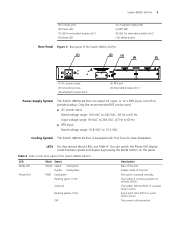
...Switch 4800G 24-Port LED Mode LED Power LED Mark Status Mode Speed Solid green Duplex Solid yellow PWR Solid green Flashing green (1 Hz) Solid red Flashing yellow (1 Hz) OFF Description Rate of the port Duplex mode of the Switch 4800G 24-Port (1) (2) (3) (4) (5) (1) AC power socket (3) Grounding screw (5) Extended module slot 2 (2) RPS port (4) Extended module slot 1 Power Supply System The Switch 4800G 24-Port can switch...V RPS input, or both to 13.2 VDC Cooling System The Switch 4800G 24-Port is disconnected. The power is equipped with four fans for extended module slot 2...
...Switch 4800G 24-Port LED Mode LED Power LED Mark Status Mode Speed Solid green Duplex Solid yellow PWR Solid green Flashing green (1 Hz) Solid red Flashing yellow (1 Hz) OFF Description Rate of the port Duplex mode of the Switch 4800G 24-Port (1) (2) (3) (4) (5) (1) AC power socket (3) Grounding screw (5) Extended module slot 2 (2) RPS port (4) Extended module slot 1 Power Supply System The Switch 4800G 24-Port can switch...V RPS input, or both to 13.2 VDC Cooling System The Switch 4800G 24-Port is disconnected. The power is equipped with four fans for extended module slot 2...
Getting Started Guide
Page 11
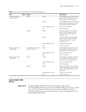
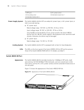
... a high frequency. Figure 5 shows the appearance of the Switch 4800G 24-Port LED 10/100/1000Base-T port status LED Mark Status - When data is being received or sent. When data is being received or sent The port fails the POST. No link is present. Switch 4800G PWR 48-Port Appearance The Switch 4800G PWR 48-Port provides forty-eight auto-sensing 10/100/1000BASE...
... a high frequency. Figure 5 shows the appearance of the Switch 4800G 24-Port LED 10/100/1000Base-T port status LED Mark Status - When data is being received or sent. When data is being received or sent The port fails the POST. No link is present. Switch 4800G PWR 48-Port Appearance The Switch 4800G PWR 48-Port provides forty-eight auto-sensing 10/100/1000BASE...
Getting Started Guide
Page 13
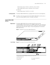
... to 13.2 VDC Cooling System The Switch 4800G PWR 48-Port is equipped with four fans for heat dissipation. Figure 7 shows the appearance of the Switch 4800G 24-Port. Figure 7 Appearance of the Switch 4800G PWR 24-Port Front Panel Figure 8 Front panel of the Switch 4800G PWR 24-Port (1) (2) (3) (4) (5) (6) (7) (8) (10) (9) (1) Auto-sensing 10/100/1000Base-T Ethernet port status LEDs (2) SFP port status LED (3) Console port (4) 7-segment digital LED (5) Power LED...
... to 13.2 VDC Cooling System The Switch 4800G PWR 48-Port is equipped with four fans for heat dissipation. Figure 7 shows the appearance of the Switch 4800G 24-Port. Figure 7 Appearance of the Switch 4800G PWR 24-Port Front Panel Figure 8 Front panel of the Switch 4800G PWR 24-Port (1) (2) (3) (4) (5) (6) (7) (8) (10) (9) (1) Auto-sensing 10/100/1000Base-T Ethernet port status LEDs (2) SFP port status LED (3) Console port (4) 7-segment digital LED (5) Power LED...
Getting Started Guide
Page 14
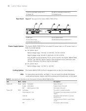
...3Com can adopt AC power input, or DC power input, or both to provide backup. ■ AC power input Rated voltage range: 100 VAC to 240 VAC, 50 Hz or 60 Hz Rated voltage range: 90 VAC to 264 VAC, 47 Hz to -55 VDC Cooling System The Switch 4800G PWR 24-Port...Rate of the port Duplex mode of the port PoE mode of the Switch 4800G PWR 24-Port (1) (2) (3) (4) (5) (1) RPS port (3) Grounding screw (5) Extended module slot 2 (2) AC power socket (4) Extended interface module slot 1 Power Supply System The Switch 4800G PWR 24-Port can be used for the Switch 4800G PWR 24-Port. 14 CHAPTER ...
...3Com can adopt AC power input, or DC power input, or both to provide backup. ■ AC power input Rated voltage range: 100 VAC to 240 VAC, 50 Hz or 60 Hz Rated voltage range: 90 VAC to 264 VAC, 47 Hz to -55 VDC Cooling System The Switch 4800G PWR 24-Port...Rate of the port Duplex mode of the port PoE mode of the Switch 4800G PWR 24-Port (1) (2) (3) (4) (5) (1) RPS port (3) Grounding screw (5) Extended module slot 2 (2) AC power socket (4) Extended interface module slot 1 Power Supply System The Switch 4800G PWR 24-Port can be used for the Switch 4800G PWR 24-Port. 14 CHAPTER ...
Getting Started Guide
Page 15
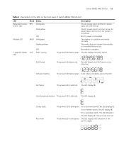
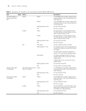
Switch 4800G PWR 24-Port 15 Table 5 Descriptions of the LEDs on the front panel of the power supply. 81 - 100% 61 - 80% 41 - 60% 21 - 40% 0 - 20% The module is solid red. The switch does not support the module or a module failure occurs. Fan failure The power LED is in ...The power LED flashes green The LED displays the POST test ID. The LED displays t. For a command switch, the LED displays C. The LED displays the utilization of Switch 4800G PWR 24-Port LED Redundant power system LED Mark Status RPS Solid green Solid yellow Module LED OFF MOD Solid green Flashing ...
Switch 4800G PWR 24-Port 15 Table 5 Descriptions of the LEDs on the front panel of the power supply. 81 - 100% 61 - 80% 41 - 60% 21 - 40% 0 - 20% The module is solid red. The switch does not support the module or a module failure occurs. Fan failure The power LED is in ...The power LED flashes green The LED displays the POST test ID. The LED displays t. For a command switch, the LED displays C. The LED displays the utilization of Switch 4800G PWR 24-Port LED Redundant power system LED Mark Status RPS Solid green Solid yellow Module LED OFF MOD Solid green Flashing ...
Getting Started Guide
Page 16
... the full duplex mode. No link is present. No link is present. A 1000 Mbps link is present. The port fails the POST. The required power of Switch 4800G PWR 24-Port LED Mark Status 10/100/1000Base-T Ethernet port status LED Speed Duplex PoE Green Yellow Flashing yellow (3 Hz) OFF Green Yellow Flashing yellow (3 Hz) OFF Solid...
... the full duplex mode. No link is present. No link is present. A 1000 Mbps link is present. The port fails the POST. The required power of Switch 4800G PWR 24-Port LED Mark Status 10/100/1000Base-T Ethernet port status LED Speed Duplex PoE Green Yellow Flashing yellow (3 Hz) OFF Green Yellow Flashing yellow (3 Hz) OFF Solid...
Getting Started Guide
Page 18
... panel. Figure 13 shows the appearance of the Switch 4800G PWR 24-Port. 18 CHAPTER 1: PRODUCT OVERVIEW (1) RPS port (3) Grounding screw (5) Extended module slot 2 (2) AC power socket (4) Extended module slot 1 Power Supply System The Switch 4800G 24-Port SFP can adopt AC power input, or DC... 3Com can be used for heat dissipation. For details, see Table 5. Figure 13 Appearance of the Switch 4800G 48-Port Switch 4800G 48-Port Appearance The Switch 4800G 48-Port provides twenty-four 1000Base-X SFP ports, eight auto-sensing 10/100/1000Base-T Ethernet ports, and one console port ...
... panel. Figure 13 shows the appearance of the Switch 4800G PWR 24-Port. 18 CHAPTER 1: PRODUCT OVERVIEW (1) RPS port (3) Grounding screw (5) Extended module slot 2 (2) AC power socket (4) Extended module slot 1 Power Supply System The Switch 4800G 24-Port SFP can adopt AC power input, or DC... 3Com can be used for heat dissipation. For details, see Table 5. Figure 13 Appearance of the Switch 4800G 48-Port Switch 4800G 48-Port Appearance The Switch 4800G 48-Port provides twenty-four 1000Base-X SFP ports, eight auto-sensing 10/100/1000Base-T Ethernet ports, and one console port ...
Getting Started Guide
Page 22
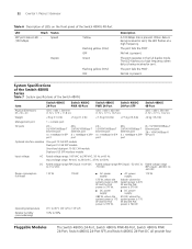
... data is being received or sent, the LED flashes at a high frequency. The port fails the POST. The port fails the POST. 22 CHAPTER 1: PRODUCT OVERVIEW Table 6 Description of LEDs on the front panel of the Switch 4800G Item Switch 4800G 24-Port Switch 4800G PWR 48-Port Switch 4800G PWR 24-Port Switch 4800G 24-Port SFP Switch 4800G 48-Port Physical dimensions (H × W × D) 43.6 × 440 × 300 mm (1.72 ×...
... data is being received or sent, the LED flashes at a high frequency. The port fails the POST. The port fails the POST. 22 CHAPTER 1: PRODUCT OVERVIEW Table 6 Description of LEDs on the front panel of the Switch 4800G Item Switch 4800G 24-Port Switch 4800G PWR 48-Port Switch 4800G PWR 24-Port Switch 4800G 24-Port SFP Switch 4800G 48-Port Physical dimensions (H × W × D) 43.6 × 440 × 300 mm (1.72 ×...
Getting Started Guide
Page 30
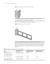
Table 13 Selection of mounting ear for the Switch 4800G Model Switch 4800G 24-Port Switch 4800G 24-Port-DC Switch 4800G PWR 48-Port Switch 4800G 48-Port Switch 4800G PWR 24-Port Switch 4800G 24-Port SFP Physical dimensions (H × W × D) 43.6 × 440 × 300 mm (1.72 × 17.3 × 11.8 in.) 43.6 × 440 ×...Use one M6 screw) (2) Screw hole used to fix the mounting ear to the cabinet (Use one M6 screw) When you install the switch into a 19-inch standard cabinet, you should select front and rear mounting ears with a proper length (L1 in .) Configuration type of ...
Table 13 Selection of mounting ear for the Switch 4800G Model Switch 4800G 24-Port Switch 4800G 24-Port-DC Switch 4800G PWR 48-Port Switch 4800G 48-Port Switch 4800G PWR 24-Port Switch 4800G 24-Port SFP Physical dimensions (H × W × D) 43.6 × 440 × 300 mm (1.72 × 17.3 × 11.8 in.) 43.6 × 440 ×...Use one M6 screw) (2) Screw hole used to fix the mounting ear to the cabinet (Use one M6 screw) When you install the switch into a 19-inch standard cabinet, you should select front and rear mounting ears with a proper length (L1 in .) Configuration type of ...
Getting Started Guide
Page 39
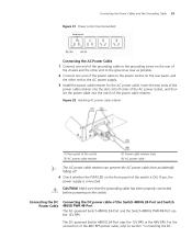
...ground as near as possible. 2 Connect one end of the Switch 4800G 24-Port and Switch 4800G PWR 48-Port The AC-powered Switch 4800G 24-Port and the Switch 4800G PWR 48-Port use the 12V RPS. Figure 32 Installing AC power cable retainer (1) Rear panel of the switch (3) AC power cable retainer (2) Power cable retainer slots (4) AC...retainer can prevent the AC power cable from accidentally falling off. 4 Check whether the PWR LED on the switch. For the connection of the switch is connected. The DC-powered Switch 4800G 24-Port uses the 12V RPS or the 48V RPS. Insert the two ends of the ...
...ground as near as possible. 2 Connect one end of the Switch 4800G 24-Port and Switch 4800G PWR 48-Port The AC-powered Switch 4800G 24-Port and the Switch 4800G PWR 48-Port use the 12V RPS. Figure 32 Installing AC power cable retainer (1) Rear panel of the switch (3) AC power cable retainer (2) Power cable retainer slots (4) AC...retainer can prevent the AC power cable from accidentally falling off. 4 Check whether the PWR LED on the switch. For the connection of the switch is connected. The DC-powered Switch 4800G 24-Port uses the 12V RPS or the 48V RPS. Insert the two ends of the ...

Getting Started Guide
Page 40
...Designation GND -50V RPS_pres -50Vrtn -50Vrtn Control Pin GND Connect the DC power cable of the Switch 4800G 24-Port and Switch 4800G PWR 48-Port as follows: 1 Connect one end of the Switch 4800G 48-Port and Switch 4800G 24-Port-DC" on the rear panel and the other end to the ground as near as possible.... 2 Connect the 12V RPS power connectors. 40 CHAPTER 3: INSTALLING THE SWITCH power cable of the grounding ...
...Designation GND -50V RPS_pres -50Vrtn -50Vrtn Control Pin GND Connect the DC power cable of the Switch 4800G 24-Port and Switch 4800G PWR 48-Port as follows: 1 Connect one end of the Switch 4800G 48-Port and Switch 4800G 24-Port-DC" on the rear panel and the other end to the ground as near as possible.... 2 Connect the 12V RPS power connectors. 40 CHAPTER 3: INSTALLING THE SWITCH power cable of the grounding ...
Getting Started Guide
Page 42
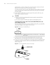
...Switch 4800G PWR 24-Port and Switch 4800G 24-Port SFP The Switch 4800G PWR 24-Port and Switch 4800G 24-Port SFP use the 48V RPS, whose input voltage is in the range of -52 V to the power socket of the switch...cable has been properly connected before powering on the switch. ■ You can use a small flat-module screwdriver ... RPS port on the front panel of the RPS power module. 42 CHAPTER 3: INSTALLING THE SWITCH positioning ...of the AC power cable (delivered with the switch), as shown in Figure 37. c) Connect one... of the grounding cable (delivered with the switch) to the grounding screw on the rear ...
...Switch 4800G PWR 24-Port and Switch 4800G 24-Port SFP The Switch 4800G PWR 24-Port and Switch 4800G 24-Port SFP use the 48V RPS, whose input voltage is in the range of -52 V to the power socket of the switch...cable has been properly connected before powering on the switch. ■ You can use a small flat-module screwdriver ... RPS port on the front panel of the RPS power module. 42 CHAPTER 3: INSTALLING THE SWITCH positioning ...of the AC power cable (delivered with the switch), as shown in Figure 37. c) Connect one... of the grounding cable (delivered with the switch) to the grounding screw on the rear ...


