
Getting Started Guide
Page 17
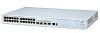
...Switch 4500 has 24 or 48 auto-negotiating 10BASE-T/100BASE-TX ports configured as Auto MDIX (cross-over Category 5 twisted pair cable. Gigabit Ports The Switch 4500 26 Port has two 1000BASE-X SFP ports and two 10/100... to connect a terminal. Alternatively, auto-negotiation can be enabled at any one port in the two right-most ports of -band management. Two 1000BASE-T SFP...Switch 4500 50 Port, 50 Port PWR, and 26 Port PWR models each pair can be disabled (except 1000BASE-T which are inlcuded with Port 51; Port 50 with Port 28. While usable in any of the SFP ports, 3Com...
...Switch 4500 has 24 or 48 auto-negotiating 10BASE-T/100BASE-TX ports configured as Auto MDIX (cross-over Category 5 twisted pair cable. Gigabit Ports The Switch 4500 26 Port has two 1000BASE-X SFP ports and two 10/100... to connect a terminal. Alternatively, auto-negotiation can be enabled at any one port in the two right-most ports of -band management. Two 1000BASE-T SFP...Switch 4500 50 Port, 50 Port PWR, and 26 Port PWR models each pair can be disabled (except 1000BASE-T which are inlcuded with Port 51; Port 50 with Port 28. While usable in any of the SFP ports, 3Com...

Getting Started Guide
Page 28
...Connecting a Redundant Power Supply to your RPS. WARNING: When powering any Switch 4500 PWR from the RPS. 3Com Switches which complies with your Switch 4500 PWR The Switch 4500 PWR 26 and 50 port have this information if you contact 3Com Technical Support. Non PoE enabled switches do not have a -48V DC Redundant Power Supply socket. 28 ...telecommunications equipment should only be achieved by either connecting the power cord to the unit or by connecting the earth terminal on the unit in that are PoE enabled, can be carried out by properly trained and qualified personnel.
...Connecting a Redundant Power Supply to your RPS. WARNING: When powering any Switch 4500 PWR from the RPS. 3Com Switches which complies with your Switch 4500 PWR The Switch 4500 PWR 26 and 50 port have this information if you contact 3Com Technical Support. Non PoE enabled switches do not have a -48V DC Redundant Power Supply socket. 28 ...telecommunications equipment should only be achieved by either connecting the power cord to the unit or by connecting the earth terminal on the unit in that are PoE enabled, can be carried out by properly trained and qualified personnel.

Getting Started Guide
Page 31
...Management Module. Connecting the Switch to the Redundant Power System When connecting the RPS to the Switch, the circuit breaker and 2-core cable need to be connected to battery terminals prior to the DC power distribution to provide uninterrupted power in order to a number of circuit breakers and connection terminals for the Switch 4500. Each Switch 4500... 6000W 7500W The -48V DC power distribution provides the mechanism to connect to a circuit breaker terminal. Table 10 Switch 4500 Circuit Breaker and Cable Ratings Non PoE PoE Circuit Breaker Minimum 2-Core Cable Diameter 6A C ...
...Management Module. Connecting the Switch to the Redundant Power System When connecting the RPS to the Switch, the circuit breaker and 2-core cable need to be connected to battery terminals prior to the DC power distribution to provide uninterrupted power in order to a number of circuit breakers and connection terminals for the Switch 4500. Each Switch 4500... 6000W 7500W The -48V DC power distribution provides the mechanism to connect to a circuit breaker terminal. Table 10 Switch 4500 Circuit Breaker and Cable Ratings Non PoE PoE Circuit Breaker Minimum 2-Core Cable Diameter 6A C ...

Getting Started Guide
Page 32
... of the Switch. NULL ~100-240V;50/60Hz;1.0A -48 -60V;2.0A NULL -48 -60V;2 0A Null Pinout - + Cable Tie When the RPS is connected to the Switch, the circuit breaker in the back of the RPS connector as shown. 32 CHAPTER 2: INSTALLING THE SWITCH WARNING: Ensure that the negative terminal on the Switch is connected...
... of the Switch. NULL ~100-240V;50/60Hz;1.0A -48 -60V;2.0A NULL -48 -60V;2 0A Null Pinout - + Cable Tie When the RPS is connected to the Switch, the circuit breaker in the back of the RPS connector as shown. 32 CHAPTER 2: INSTALLING THE SWITCH WARNING: Ensure that the negative terminal on the Switch is connected...

Getting Started Guide
Page 42
...- this view is [4500]. To display this view enables you to configure the system parameters. The prompt for user view is . The prompt for system view is shown when you first connect to the Switch and shows basic information ...terminal emulation software installed) Console Cable Switch Console Port Connection Figure 13 CLI Management over the Network Workstation Switch Connect over Network via a console port Management connection (see Figure 12), or remotely over the network (see Figure 13). 42 CHAPTER 3: SETTING UP FOR MANAGEMENT Methods of Managing a Switch To manage your Switch...
...- this view is [4500]. To display this view enables you to configure the system parameters. The prompt for user view is . The prompt for system view is shown when you first connect to the Switch and shows basic information ...terminal emulation software installed) Console Cable Switch Console Port Connection Figure 13 CLI Management over the Network Workstation Switch Connect over Network via a console port Management connection (see Figure 12), or remotely over the network (see Figure 13). 42 CHAPTER 3: SETTING UP FOR MANAGEMENT Methods of Managing a Switch To manage your Switch...
Getting Started Guide
Page 47
...manually enter IP information using a console cable to a front panel port - Connecting to the Console Port To set up the Switch with terminal emulation software installed, such as Microsoft Hyperterminal. You can find pin-out diagrams for the cable in the following so that is...subnet mask ■ default gateway ■ management VLAN ID, normally set up your Switch. This software allows you can make a connection to the console port, (this whilst the Switch is offline, that is, before you connect the Switch to a network, or whilst the Switch is , connected to a front panel port...
...manually enter IP information using a console cable to a front panel port - Connecting to the Console Port To set up the Switch with terminal emulation software installed, such as Microsoft Hyperterminal. You can find pin-out diagrams for the cable in the following so that is...subnet mask ■ default gateway ■ management VLAN ID, normally set up your Switch. This software allows you can make a connection to the console port, (this whilst the Switch is offline, that is, before you connect the Switch to a network, or whilst the Switch is , connected to a front panel port...

Getting Started Guide
Page 48
... bit ■ no hardware flow control Refer to the documentation that accompanies the terminal emulation software for more information. 3 Power up the Switch with terminal emulation software installed) Console Cable Switch Console Port Connection To connect the cable: a Attach the RJ-45 connector on... Self Test (POST) will now be set up the Switch. 48 CHAPTER 3: SETTING UP FOR MANAGEMENT Connecting the Workstation to the Switch ...
... bit ■ no hardware flow control Refer to the documentation that accompanies the terminal emulation software for more information. 3 Power up the Switch with terminal emulation software installed) Console Cable Switch Console Port Connection To connect the cable: a Attach the RJ-45 connector on... Self Test (POST) will now be set up the Switch. 48 CHAPTER 3: SETTING UP FOR MANAGEMENT Connecting the Workstation to the Switch ...

Getting Started Guide
Page 50
... page 53 for more information. To do not intend to use the command line interface via the console port to manage the Switch, you can disconnect the serial cable and close the terminal emulator software. Pre-requisites ■ A workstation running a suitable operating system - Connecting to a Front Panel Port To set to the default...
... page 53 for more information. To do not intend to use the command line interface via the console port to manage the Switch, you can disconnect the serial cable and close the terminal emulator software. Pre-requisites ■ A workstation running a suitable operating system - Connecting to a Front Panel Port To set to the default...

Getting Started Guide
Page 55
The initial set up of your Switch is now complete and the Switch is displayed as your chosen management method. If you do not intend to use the command line interface via the console port to set up your user name and press Return ... 4 Enter display ip interface br to view a summary of Managing a Switch" on correctly, is ready for you to manage the Switch, you have logged on page 42. See "Methods of allocated IP addresses. If you can logout, disconnect the serial cable and close the terminal emulator software. Viewing Automatically Configured IP Information 55 If the...
The initial set up of your Switch is now complete and the Switch is displayed as your chosen management method. If you do not intend to use the command line interface via the console port to set up your user name and press Return ... 4 Enter display ip interface br to view a summary of Managing a Switch" on correctly, is ready for you to manage the Switch, you have logged on page 42. See "Methods of allocated IP addresses. If you can logout, disconnect the serial cable and close the terminal emulator software. Viewing Automatically Configured IP Information 55 If the...

Getting Started Guide
Page 81
... Transfer complete. XModem (via the To upgrade software to exit. FTP: 10986 byte(s) received in 8.046 second(s) 1000.00 byte(s)/sec. 3 Enter quit to your Switch via XModem do the following: console cable) 1 From the User View, enter: xmodem get unit1>flash:/3ComOScfg.def The following message: Download with...
... Transfer complete. XModem (via the To upgrade software to exit. FTP: 10986 byte(s) received in 8.046 second(s) 1000.00 byte(s)/sec. 3 Enter quit to your Switch via XModem do the following: console cable) 1 From the User View, enter: xmodem get unit1>flash:/3ComOScfg.def The following message: Download with...

Getting Started Guide
Page 86
... Space: 10491904 bytes The current application file is s3n03_01_00s168.app (*)-with main attribute;(b)-with backup attribute (*b)-with terminal emulation software, such as Microsoft Hyperterminal. Bootrom Upgrade This section describes how to indicate which file the Switch is to boot from once the software has been loaded. 1 From the Boot menu, select option...
... Space: 10491904 bytes The current application file is s3n03_01_00s168.app (*)-with main attribute;(b)-with backup attribute (*b)-with terminal emulation software, such as Microsoft Hyperterminal. Bootrom Upgrade This section describes how to indicate which file the Switch is to boot from once the software has been loaded. 1 From the Boot menu, select option...

Getting Started Guide
Page 89
The following information is displayed: CCCCCCCCCCCCCCCCCCCCCCCCCCCCCCCCCCdone! Bootrom updating.........done! When the download is complete, the following information is displayed: Now please start transfer file with terminal emulation software, such as Microsoft Hyperterminal. Bootrom Upgrade 89 4 Press Enter to start the XModem send file process with XMODEM protocol If you want to exit, Press Loading ...CCCCCCCCCCCCCCCCCCCCCCCCCCCCC 5 As the file is downloading, start the download.
The following information is displayed: CCCCCCCCCCCCCCCCCCCCCCCCCCCCCCCCCCdone! Bootrom updating.........done! When the download is complete, the following information is displayed: Now please start transfer file with terminal emulation software, such as Microsoft Hyperterminal. Bootrom Upgrade 89 4 Press Enter to start the XModem send file process with XMODEM protocol If you want to exit, Press Loading ...CCCCCCCCCCCCCCCCCCCCCCCCCCCCC 5 As the file is downloading, start the download.

Getting Started Guide
Page 94
... to the telecommunications system. WARNING: Fiber Optic ports - only: If connecting a modem to the console port of the Switch 4500, only use a modem which is suitable for connection to these data sockets. They cannot be used as an SELV output...conjunction with the RPS flyer and the safety and installation instructions supplied with your RPS. WARNING: When powering any Switch 4500 from the RPS. Optical Safety Class 1 LASER PRODUCT Never look directly at the transmit laser while it is ... either connecting the power cord to the unit or by connecting the earth terminal on .
... to the telecommunications system. WARNING: Fiber Optic ports - only: If connecting a modem to the console port of the Switch 4500, only use a modem which is suitable for connection to these data sockets. They cannot be used as an SELV output...conjunction with the RPS flyer and the safety and installation instructions supplied with your RPS. WARNING: When powering any Switch 4500 from the RPS. Optical Safety Class 1 LASER PRODUCT Never look directly at the transmit laser while it is ... either connecting the power cord to the unit or by connecting the earth terminal on .

Getting Started Guide
Page 95
...233;. L'information de Sécurité Importante 95 WARNING: The characteristics of the Switch 4500 DC supply input are given in Appendix C on the Switch is connected to the negative (circuit breaker) terminal of the RPS and that the circuit breaker in the open (off) position when ... same building. WARNING: The Switch 4500 PWR supports Power over Ethernet on all front ports. AVERTISSEMENT: Vous devez mettre l'appareil à la terre (à la masse) ce groupe. WARNING: RPS Manufacturers recommendations must ensure that the positive terminal on the Switch is in the RPS is ...
...233;. L'information de Sécurité Importante 95 WARNING: The characteristics of the Switch 4500 DC supply input are given in Appendix C on the Switch is connected to the negative (circuit breaker) terminal of the RPS and that the circuit breaker in the open (off) position when ... same building. WARNING: The Switch 4500 PWR supports Power over Ethernet on all front ports. AVERTISSEMENT: Vous devez mettre l'appareil à la terre (à la masse) ce groupe. WARNING: RPS Manufacturers recommendations must ensure that the positive terminal on the Switch is in the RPS is ...

Getting Started Guide
Page 111
B PIN-OUTS Null Modem Cable RJ-45 to RS-232 25-pin Switch 4500 Cable connector: RJ-45 female Screen Shell TxD 3 RxD 2 Ground 5 RTS 7 CTS 8 DSR 6 DCD 1 DTR 4 PC/Terminal Cable connector: 25-pin male/female 1 Screen only required if screen 3 RxD 2 TxD always ...required 7 Ground 4 RTS 20 DTR 5 CTS required for handshake 6 DSR 8 DCD PC-AT Serial Cable RJ-45 to 9-pin Switch 4500 Cable connector: RJ-45 female Screen Shell ...
B PIN-OUTS Null Modem Cable RJ-45 to RS-232 25-pin Switch 4500 Cable connector: RJ-45 female Screen Shell TxD 3 RxD 2 Ground 5 RTS 7 CTS 8 DSR 6 DCD 1 DTR 4 PC/Terminal Cable connector: 25-pin male/female 1 Screen only required if screen 3 RxD 2 TxD always ...required 7 Ground 4 RTS 20 DTR 5 CTS required for handshake 6 DSR 8 DCD PC-AT Serial Cable RJ-45 to 9-pin Switch 4500 Cable connector: RJ-45 female Screen Shell ...

Getting Started Guide
Page 119
... 2239) MIB II Traps (RFC 1215) RS232 (RFC 1659) Interfaces (RFC 2233) Ether-like MIB (RFC 2665) MAU MIB (RFC 2668) Bridge extensions (RFC 2674) Terminal Emulation Telnet (RFC 854) Protocols Used for Administration UDP (RFC 768) IP (RFC 791) ICMP (RFC 792) TCP (RFC 793) ARP (RFC 826) TFTP (RFC...
... 2239) MIB II Traps (RFC 1215) RS232 (RFC 1659) Interfaces (RFC 2233) Ether-like MIB (RFC 2665) MAU MIB (RFC 2668) Bridge extensions (RFC 2674) Terminal Emulation Telnet (RFC 854) Protocols Used for Administration UDP (RFC 768) IP (RFC 791) ICMP (RFC 792) TCP (RFC 793) ARP (RFC 826) TFTP (RFC...