
Getting Started Guide
Page 3
Front View Detail 15 10BASE-T/ 100BASE-TX Ports 17 Gigabit Ports 17 Console Port 17 Unit LED 18 LEDs 18 Switch 4500 - Rear View Detail 20 Power Socket 20 Open Book Warning Labels 20 Redundant Power System Socket 21 Default Settings 21 CONTENTS ABOUT THIS GUIDE Before You Start 9 Release Notes 9 About Your CD-ROM 10 Conventions 10 Related Documentation 11 Accessing Online Documentation 12 Documentation Comments 12 1 INTRODUCING THE SWITCH 4500 FAMILY About the Switch 4500 14 Summary of Hardware Features 15 Switch 4500 -
Front View Detail 15 10BASE-T/ 100BASE-TX Ports 17 Gigabit Ports 17 Console Port 17 Unit LED 18 LEDs 18 Switch 4500 - Rear View Detail 20 Power Socket 20 Open Book Warning Labels 20 Redundant Power System Socket 21 Default Settings 21 CONTENTS ABOUT THIS GUIDE Before You Start 9 Release Notes 9 About Your CD-ROM 10 Conventions 10 Related Documentation 11 Accessing Online Documentation 12 Documentation Comments 12 1 INTRODUCING THE SWITCH 4500 FAMILY About the Switch 4500 14 Summary of Hardware Features 15 Switch 4500 -

Getting Started Guide
Page 16
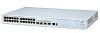
... transceivers in last two ports) Figure 3 Switch 4500 26-Port PWR - They cannot be connected to these sockets. front view Speed:Green = 100Mbps, Yellow = 10Mbps Duplex:Green = Full Duplex, Yellow = Half Duplex Port Status LEDs 10/100BASE-TX Ports Console Port Unit LED PWR LED 3CR17562-91 SuperStack 3 Switch 4500 50-Port 49 50 51/49 52...
... transceivers in last two ports) Figure 3 Switch 4500 26-Port PWR - They cannot be connected to these sockets. front view Speed:Green = 100Mbps, Yellow = 10Mbps Duplex:Green = Full Duplex, Yellow = Half Duplex Port Status LEDs 10/100BASE-TX Ports Console Port Unit LED PWR LED 3CR17562-91 SuperStack 3 Switch 4500 50-Port 49 50 51/49 52...

Getting Started Guide
Page 20
... installing or removing any components from the Switch 4500 or Labels carrying out any supply voltage in the range 100-240 VAC. rear view Open Book Warning Labels ~100-240V; 50/60Hz; 1A Power Socket Figure 6 Switch 4500 PWR - AVERTISSEMENT: Avant d'installer ou d'enlever tout composant des commutateurs de la gamme Switch 4500 ou d'entamer une procédure...
... installing or removing any components from the Switch 4500 or Labels carrying out any supply voltage in the range 100-240 VAC. rear view Open Book Warning Labels ~100-240V; 50/60Hz; 1A Power Socket Figure 6 Switch 4500 PWR - AVERTISSEMENT: Avant d'installer ou d'enlever tout composant des commutateurs de la gamme Switch 4500 ou d'entamer une procédure...
Getting Started Guide
Page 21
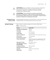
...(VLAN 1) with IEEE Std 802.1Q-1998 learning operational Management VLAN Any VLAN for all ports) and System Socket redundant power for the Switch 4500 Family: Table 6 Default Settings Feature Switch 4500 Automatic IP Configuration Enabled Port Status Enabled Port Speed Auto-...negotiated Duplex Mode Auto-negotiated Power over Ethernet Enabled (3CR17571-91 and 3CR17572-91 only) Flow Control...
...(VLAN 1) with IEEE Std 802.1Q-1998 learning operational Management VLAN Any VLAN for all ports) and System Socket redundant power for the Switch 4500 Family: Table 6 Default Settings Feature Switch 4500 Automatic IP Configuration Enabled Port Status Enabled Port Speed Auto-...negotiated Duplex Mode Auto-negotiated Power over Ethernet Enabled (3CR17571-91 and 3CR17572-91 only) Flow Control...

Getting Started Guide
Page 28
...: ■ 3Com product name of the Switch ■ 3Com 3C number of the Switch ■ Unique MAC address (Ethernet address) of the Switch. ■ Serial number of IEEE-Std 802.3af. Non PoE enabled switches do not have a -48V DC Redundant Power Supply socket. 28 CHAPTER 2: INSTALLING THE SWITCH 6 Finally, ... requirements in an easily accessible position. WARNING: These instructions must be used with your Switch 4500 PWR The Switch 4500 PWR 26 and 50 port have this information if you contact 3Com Technical Support. This can only be read in conjunction with the RPS flyer and the...
...: ■ 3Com product name of the Switch ■ 3Com 3C number of the Switch ■ Unique MAC address (Ethernet address) of the Switch. ■ Serial number of IEEE-Std 802.3af. Non PoE enabled switches do not have a -48V DC Redundant Power Supply socket. 28 CHAPTER 2: INSTALLING THE SWITCH 6 Finally, ... requirements in an easily accessible position. WARNING: These instructions must be used with your Switch 4500 PWR The Switch 4500 PWR 26 and 50 port have this information if you contact 3Com Technical Support. This can only be read in conjunction with the RPS flyer and the...

Getting Started Guide
Page 32
... to the negative (circuit breaker) terminal of the RPS. Figure 9 shows how to connect the power supply to the RPS socket in the RPS can be moved to the closed (on the Switch is connected to the positive (common) terminal of the RPS and that the negative terminal on ) position and the... Switch will be powered by the -48V DC power. Use the cable tie supplied with your Switch to the Switch + - NULL ~100-240V;50/60Hz;1.0A -48 -60V;2.0A NULL -48 -60V;2 0A Null Pinout - + Cable Tie When...
... to the negative (circuit breaker) terminal of the RPS. Figure 9 shows how to connect the power supply to the RPS socket in the RPS can be moved to the closed (on the Switch is connected to the positive (common) terminal of the RPS and that the negative terminal on ) position and the... Switch will be powered by the -48V DC power. Use the cable tie supplied with your Switch to the Switch + - NULL ~100-240V;50/60Hz;1.0A -48 -60V;2.0A NULL -48 -60V;2 0A Null Pinout - + Cable Tie When...

Getting Started Guide
Page 35
Switch 4500 1 Plug the power cord into the power socket at the rear of the Switch. 2 Plug the other end of the ports with a straight-through its Power ... whether to get your power outlet. Self Test (POST) or Software Download is not receiving power. The Switch is in MDI or MDIX mode. the only method of connecting or disconnecting mains power is they have a... following sections describe how to operate in progress The Switch has failed its Power On Self Test (POST), which takes approximately one of the power cord into your Switch 4500 powered-up and ready for a list of LEDs...
Switch 4500 1 Plug the power cord into the power socket at the rear of the Switch. 2 Plug the other end of the ports with a straight-through its Power ... whether to get your power outlet. Self Test (POST) or Software Download is not receiving power. The Switch is in MDI or MDIX mode. the only method of connecting or disconnecting mains power is they have a... following sections describe how to operate in progress The Switch has failed its Power On Self Test (POST), which takes approximately one of the power cord into your Switch 4500 powered-up and ready for a list of LEDs...

Getting Started Guide
Page 93
... SV or SJ 3-conductor ■ The cord set must be powered by 230V (2P+T) via an isolation transformer ratio 1:1, with SEV/ASE 1011. WARNING: The socket outlet must comply with the secondary connection point labelled Neutral, connected directly to the unit and easily accessible. WARNING: France and Peru only: This unit...
... SV or SJ 3-conductor ■ The cord set must be powered by 230V (2P+T) via an isolation transformer ratio 1:1, with SEV/ASE 1011. WARNING: The socket outlet must comply with the secondary connection point labelled Neutral, connected directly to the unit and easily accessible. WARNING: France and Peru only: This unit...

Getting Started Guide
Page 94
... reliable electrical earth, or by properly trained and qualified personnel. Disconnect all power inputs to the telecommunications system. WARNING: When powering any Switch 4500 from the RPS. WARNING: RJ-45 Ports. Either shielded or unshielded data cables with IEC 60950-1/UL 60950-1/EN 60950-1. Never look... unit to these sockets. Optical Safety Class 1 LASER PRODUCT Never look directly at the transmit laser while it is made before connecting the DC supply from an RPS, the unit must be carried out by connecting both. WARNING: The installation of the Switch 4500, only use a...
... reliable electrical earth, or by properly trained and qualified personnel. Disconnect all power inputs to the telecommunications system. WARNING: When powering any Switch 4500 from the RPS. WARNING: RJ-45 Ports. Either shielded or unshielded data cables with IEC 60950-1/UL 60950-1/EN 60950-1. Never look... unit to these sockets. Optical Safety Class 1 LASER PRODUCT Never look directly at the transmit laser while it is made before connecting the DC supply from an RPS, the unit must be carried out by connecting both. WARNING: The installation of the Switch 4500, only use a...

Getting Started Guide
Page 125
...default users 60 automatic setup 53 3Com Network Director 54 console port 54 B browsers choosing 58 C cable 10/100/1000 35 pin-outs 111 CD-ROM 12 command line interface management 42 console port 17 conventions notice icons, About This Guide 10 text, About This Guide 10 cross-over configuration 35 D ... passwords of default users 60 pin assignments modem cable 112 null modem cable 111 RJ45 112 serial cable 111 pin-outs 111 ports 17 power over ethernet (PoE) 33 power socket 20 powering-up a Switch 4500 35 problem solving 67, 75 communication problems 71 hardware problems 69 IP addressing 69 ...
...default users 60 automatic setup 53 3Com Network Director 54 console port 54 B browsers choosing 58 C cable 10/100/1000 35 pin-outs 111 CD-ROM 12 command line interface management 42 console port 17 conventions notice icons, About This Guide 10 text, About This Guide 10 cross-over configuration 35 D ... passwords of default users 60 pin assignments modem cable 112 null modem cable 111 RJ45 112 serial cable 111 pin-outs 111 ports 17 power over ethernet (PoE) 33 power socket 20 powering-up a Switch 4500 35 problem solving 67, 75 communication problems 71 hardware problems 69 IP addressing 69 ...

Getting Started Guide
Page 126
See SNMP SNMP 59 SNMP management 43 setting up 59 socket power 20 specifications, system 115 SSH 57 stacking 35 straight-through configuration 35 Switch automatic setup 53 Switch 4500 dimensions 115 features 15 installation 23, 25 power socket 20 powering-up 35 rack mounting 26 size 115 weight ... 58 web interface choosing a browser 58 web interface management 43 setting up 58 X XModem 81 XRN Distributed Fabric 63 Guidelines for Interconnecting Units 64 How to Interconnect Units 63 Unit Numbering 65 126 INDEX R rack mounting a Switch 4500 26 redundant power supply (RPS) 28 related documentation ...
See SNMP SNMP 59 SNMP management 43 setting up 59 socket power 20 specifications, system 115 SSH 57 stacking 35 straight-through configuration 35 Switch automatic setup 53 Switch 4500 dimensions 115 features 15 installation 23, 25 power socket 20 powering-up 35 rack mounting 26 size 115 weight ... 58 web interface choosing a browser 58 web interface management 43 setting up 58 X XModem 81 XRN Distributed Fabric 63 Guidelines for Interconnecting Units 64 How to Interconnect Units 63 Unit Numbering 65 126 INDEX R rack mounting a Switch 4500 26 redundant power supply (RPS) 28 related documentation ...