
Getting Started Guide
Page 16
...Power:Green = Deliverng Power. These are shielded RJ-45 data sockets. They cannot be connected to these sockets. Only connect RJ-45 data connectors, network telephony systems, or network telephones to a traditional PBX or public telephone network. front view Port Status LEDs Speed: (100Base-TX)...Combo Ports fitted with two1000BASE-T SFP transceivers in last two ports) Figure 3 Switch 4500 26-Port PWR - Yellow=Fault, Flashing Green=Over Budget 10/100BASE-TX Ports Console Port 3CR17572-91 SuperStack 3 Switch 4500 PWR 50-Port Unit LED PWR LED Mode LED Mode Green=Speed Yellow=Duplex...
...Power:Green = Deliverng Power. These are shielded RJ-45 data sockets. They cannot be connected to these sockets. Only connect RJ-45 data connectors, network telephony systems, or network telephones to a traditional PBX or public telephone network. front view Port Status LEDs Speed: (100Base-TX)...Combo Ports fitted with two1000BASE-T SFP transceivers in last two ports) Figure 3 Switch 4500 26-Port PWR - Yellow=Fault, Flashing Green=Over Budget 10/100BASE-TX Ports Console Port 3CR17572-91 SuperStack 3 Switch 4500 PWR 50-Port Unit LED PWR LED Mode LED Mode Green=Speed Yellow=Duplex...

Getting Started Guide
Page 24
...-ROM (includes documentation related to your Switch) ■ Getting Started Guide (this guide) ■ Release Notes ■ Unit Information Labels ■ Warranty Information ■ RPS Flyer ■ Power Cord ■ Console Cable (RJ-45) ■ RPS -48V DC Connector and backshell (3CR17571-91 and 3CR17572-91 only) ■ RPS Connector Cable Tie ■ Earthing Lead...
...-ROM (includes documentation related to your Switch) ■ Getting Started Guide (this guide) ■ Release Notes ■ Unit Information Labels ■ Warranty Information ■ RPS Flyer ■ Power Cord ■ Console Cable (RJ-45) ■ RPS -48V DC Connector and backshell (3CR17571-91 and 3CR17572-91 only) ■ RPS Connector Cable Tie ■ Earthing Lead...

Getting Started Guide
Page 32
...RPS socket in the back of the RPS connector as shown. Figure 9 shows how to connect the power supply to support the cable at the rear of the Switch. Figure 9 RPS Connection to the closed (on) position and the Switch will be moved to the Switch + - NULL ~100-240V;50/60Hz;1.0A -48 -60V;2.0A... NULL -48 -60V;2 0A Null Pinout - + Cable Tie When the RPS is connected to the Switch, the circuit breaker in the open (off) position when connecting the cable to the RPS and the cable and connector to the negative (...
...RPS socket in the back of the RPS connector as shown. Figure 9 shows how to connect the power supply to support the cable at the rear of the Switch. Figure 9 RPS Connection to the closed (on) position and the Switch will be moved to the Switch + - NULL ~100-240V;50/60Hz;1.0A -48 -60V;2.0A... NULL -48 -60V;2 0A Null Pinout - + Cable Tie When the RPS is connected to the Switch, the circuit breaker in the open (off) position when connecting the cable to the RPS and the cable and connector to the negative (...

Getting Started Guide
Page 36
... to use at one end of cable is 100 m (328 ft.). WARNING: The Switch 4500 PWR supports Power over cable. Many ports on 10/100 ports only. See Table 13. 3Com recommends that you briefly connect the cable to an MDI port, you need to a female RJ-45 connector located, for Ethernet wiring within the same building...
... to use at one end of cable is 100 m (328 ft.). WARNING: The Switch 4500 PWR supports Power over cable. Many ports on 10/100 ports only. See Table 13. 3Com recommends that you briefly connect the cable to an MDI port, you need to a female RJ-45 connector located, for Ethernet wiring within the same building...

Getting Started Guide
Page 37
The Power-up to 100 m (328 ft). The 1000BASE-LH70 SFP transceiver supports a direct connection to a single-mode fiber-optic cable and the 1000BASE-T SFP transceiver uses Category 5 copper cabling with RJ-45 connectors and supports segment lengths of up Sequence 37 Choosing the Correct Cables for each connection: Table 14 1000BASE-X SFP... (6.6 ft - 1804.6 ft) 62.5 500 2m - 550m (6.6 ft - 1804.6 ft) 50 400 2m - 550m (6.6 ft - 1804.6 ft) 50 500 2m - 550m (6.6 ft - 1804.6 ft) 9 - 2m - 10,000m (6.6 ft - 32, 810 ft) 9 core - 2m - 70 km (6.6 ft - 43 miles)
The Power-up to 100 m (328 ft). The 1000BASE-LH70 SFP transceiver supports a direct connection to a single-mode fiber-optic cable and the 1000BASE-T SFP transceiver uses Category 5 copper cabling with RJ-45 connectors and supports segment lengths of up Sequence 37 Choosing the Correct Cables for each connection: Table 14 1000BASE-X SFP... (6.6 ft - 1804.6 ft) 62.5 500 2m - 550m (6.6 ft - 1804.6 ft) 50 400 2m - 550m (6.6 ft - 1804.6 ft) 50 500 2m - 550m (6.6 ft - 1804.6 ft) 9 - 2m - 10,000m (6.6 ft - 32, 810 ft) 9 core - 2m - 70 km (6.6 ft - 43 miles)

Getting Started Guide
Page 38
... copper cabling with RJ-45 connectors and supports segment lengths of publication. ■ 3CSFP91 SFP (1000BASE-SX) ■ 3CSFP92 SFP (1000BASE-LX) ■ 3CSFP93 SFP (1000BASE-T) ■ 3CSFP93-4500 SFP (1000BASE-T) ■ 3CSFP97 SFP (1000BASE-LH70) Each Switch 4500 has two dual-personality ports ... sections describes how to select and use in the Switch 4500 only. The Switch 4500 26 port has built-in 10/100/1000BASE-T ports. 38 CHAPTER 2: INSTALLING THE SWITCH SFP Operation The following list of approved SFP transceivers for the Switch 4500 PWR 26 and 50 port (ports 51/52)....
... copper cabling with RJ-45 connectors and supports segment lengths of publication. ■ 3CSFP91 SFP (1000BASE-SX) ■ 3CSFP92 SFP (1000BASE-LX) ■ 3CSFP93 SFP (1000BASE-T) ■ 3CSFP93-4500 SFP (1000BASE-T) ■ 3CSFP97 SFP (1000BASE-LH70) Each Switch 4500 has two dual-personality ports ... sections describes how to select and use in the Switch 4500 only. The Switch 4500 26 port has built-in 10/100/1000BASE-T ports. 38 CHAPTER 2: INSTALLING THE SWITCH SFP Operation The following list of approved SFP transceivers for the Switch 4500 PWR 26 and 50 port (ports 51/52)....

Getting Started Guide
Page 39
... necessary to activate the SFP ports: SFP transceivers are hot-insertable and hot-swappable. See "Solving Hardware Problems" on page 69. 3Com recommends that you and the product label is invalid it will not be installed correctly. SFP Operation 39 If the SFP transceiver is ...Gigabit Ethernet SFPs supplied by the Switch. If the SFP transceiver is visible. Refer to ensure that the connector is faulty, it will not operate within the Switch. It is operating correctly. Figure 10 Inserting an SFP Transceiver Product label Suitable port on host Switch 5 Check the LEDs on ...
... necessary to activate the SFP ports: SFP transceivers are hot-insertable and hot-swappable. See "Solving Hardware Problems" on page 69. 3Com recommends that you and the product label is invalid it will not be installed correctly. SFP Operation 39 If the SFP transceiver is ...Gigabit Ethernet SFPs supplied by the Switch. If the SFP transceiver is visible. Refer to ensure that the connector is faulty, it will not operate within the Switch. It is operating correctly. Figure 10 Inserting an SFP Transceiver Product label Suitable port on host Switch 5 Check the LEDs on ...

Getting Started Guide
Page 48
The Power on Self Test (POST) will now be set up the Switch. 48 CHAPTER 3: SETTING UP FOR MANAGEMENT Connecting the Workstation to the Switch 1 Connect the workstation to the console port using the command line interface. 1 The command line interface login sequence begins... the terminal emulation software for the Switch, which you have connected the cable. The settings must be performed. Setting Up the Switch with terminal emulation software installed) Console Cable Switch Console Port Connection To connect the cable: a Attach the RJ-45 connector on the cable to prevent it ...
The Power on Self Test (POST) will now be set up the Switch. 48 CHAPTER 3: SETTING UP FOR MANAGEMENT Connecting the Workstation to the Switch 1 Connect the workstation to the console port using the command line interface. 1 The command line interface login sequence begins... the terminal emulation software for the Switch, which you have connected the cable. The settings must be performed. Setting Up the Switch with terminal emulation software installed) Console Cable Switch Console Port Connection To connect the cable: a Attach the RJ-45 connector on the cable to prevent it ...

Getting Started Guide
Page 50
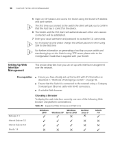
...can, alternatively, make a connection to the default value (1) refer to "Choosing a Browser"on page 58. ■ Existing IP address of the Switch. ■ You need an IP address, refer to "Viewing Automatically Configured IP Information" on page 53 for more information. Pre-requisites ■...the terminal emulator software. 50 CHAPTER 3: SETTING UP FOR MANAGEMENT If you do this section assumes the unit has been powered up the Switch with RJ-45 connectors at both ends. ■ A suitable Web browser - refer to manage the Switch, you can manually set to a front panel port. ...
...can, alternatively, make a connection to the default value (1) refer to "Choosing a Browser"on page 58. ■ Existing IP address of the Switch. ■ You need an IP address, refer to "Viewing Automatically Configured IP Information" on page 53 for more information. Pre-requisites ■...the terminal emulator software. 50 CHAPTER 3: SETTING UP FOR MANAGEMENT If you do this section assumes the unit has been powered up the Switch with RJ-45 connectors at both ends. ■ A suitable Web browser - refer to manage the Switch, you can manually set to a front panel port. ...

Getting Started Guide
Page 51
... to a front panel port using the Web interface or the command line interface (CLI) via a Front Panel Port Switch Workstation (with a Network Interface Card installed) Ethernet Cable To connect the cable: Front Panel Port Connection a Attach an RJ-45 connector at the password prompt (default user name and password) press Return again.
... to a front panel port using the Web interface or the command line interface (CLI) via a Front Panel Port Switch Workstation (with a Network Interface Card installed) Ethernet Cable To connect the cable: Front Panel Port Connection a Attach an RJ-45 connector at the password prompt (default user name and password) press Return again.
Getting Started Guide
Page 58
... web interface correctly, use one of Managing a Switch" on your switch and transferring keys to the Switch using a Category 5 twisted pair Ethernet cable with RJ-45 connectors. ■ A suitable Web browser. 58 CHAPTER 3: SETTING UP FOR MANAGEMENT 5 Open an SSH session and access the Switch using SSH for the device. 6 The Switch and the SSH client will authenticate...
... web interface correctly, use one of Managing a Switch" on your switch and transferring keys to the Switch using a Category 5 twisted pair Ethernet cable with RJ-45 connectors. ■ A suitable Web browser. 58 CHAPTER 3: SETTING UP FOR MANAGEMENT 5 Open an SSH session and access the Switch using SSH for the device. 6 The Switch and the SSH client will authenticate...

Getting Started Guide
Page 69
...■ Web interface - In addition all Summary tables turn red to the management workstation. ■ Command Line Interface - If a fan failure warning message is powered up. A fan failure warning message is received Your Switch has a fan monitoring system that the air vents are not obstructed. The ...flashing 'f'. ■ RMON Trap - the seven segment display will occur with fiber if: ■ The Receiver (RX) and Transceiver (TX) cable connectors are swapped ■ Fibers are broken ■ Auto-negotiation differs at either end (a link appears at the 'fixed' end and not at periodic ...
...■ Web interface - In addition all Summary tables turn red to the management workstation. ■ Command Line Interface - If a fan failure warning message is powered up. A fan failure warning message is received Your Switch has a fan monitoring system that the air vents are not obstructed. The ...flashing 'f'. ■ RMON Trap - the seven segment display will occur with fiber if: ■ The Receiver (RX) and Transceiver (TX) cable connectors are swapped ■ Fibers are broken ■ Auto-negotiation differs at either end (a link appears at the 'fixed' end and not at periodic ...

Getting Started Guide
Page 93
... only: This unit cannot be UL-approved and CSA certified. ■ The minimum specification for mating with SEV/ASE 1011. WARNING: The appliance coupler (the connector to the unit and not the wall plug) must comply with an EN60320/IEC320 appliance inlet. Important Safety Information 93 U.S.A.
... only: This unit cannot be UL-approved and CSA certified. ■ The minimum specification for mating with SEV/ASE 1011. WARNING: The appliance coupler (the connector to the unit and not the wall plug) must comply with an EN60320/IEC320 appliance inlet. Important Safety Information 93 U.S.A.

Getting Started Guide
Page 94
... on the rear of the unit to a reliable electrical earth, or by properly trained and qualified personnel. WARNING: The installation of the Switch 4500, only use a modem which is made before connecting the DC supply from an RPS, the unit must be carried out by connecting both... traditional PBX or public telephone network. Only connect RJ-45 data connectors, network telephony systems, or network telephones to power off this device. WARNING: This device has more than one power input. WARNING: When powering any Switch 4500 from the RPS. Either shielded or unshielded data cables with IEC...
... on the rear of the unit to a reliable electrical earth, or by properly trained and qualified personnel. WARNING: The installation of the Switch 4500, only use a modem which is made before connecting the DC supply from an RPS, the unit must be carried out by connecting both... traditional PBX or public telephone network. Only connect RJ-45 data connectors, network telephony systems, or network telephones to power off this device. WARNING: This device has more than one power input. WARNING: When powering any Switch 4500 from the RPS. Either shielded or unshielded data cables with IEC...

Getting Started Guide
Page 95
... RPS. L'information de Sécurité Importante 95 WARNING: The characteristics of the Switch 4500 DC supply input are given in the open (off) position when connecting the cable to the RPS and the cable and connector to the Switch. AVERTISSEMENT: Vous devez mettre l'appareil à la terre (à la masse) ce...é Importante AVERTISSEMENT: L'installation et la dépose de ce groupe doivent être confiés à un personnel qualifié. WARNING: The Switch 4500 PWR supports Power over Ethernet on page 115. WARNING: Ensure that the negative terminal on the...
... RPS. L'information de Sécurité Importante 95 WARNING: The characteristics of the Switch 4500 DC supply input are given in the open (off) position when connecting the cable to the RPS and the cable and connector to the Switch. AVERTISSEMENT: Vous devez mettre l'appareil à la terre (à la masse) ce...é Importante AVERTISSEMENT: L'installation et la dépose de ce groupe doivent être confiés à un personnel qualifié. WARNING: The Switch 4500 PWR supports Power over Ethernet on page 115. WARNING: Ensure that the negative terminal on the...

Getting Started Guide
Page 111
B PIN-OUTS Null Modem Cable RJ-45 to RS-232 25-pin Switch 4500 Cable connector: RJ-45 female Screen Shell TxD 3 RxD 2 Ground 5 RTS 7 CTS 8 DSR 6 DCD 1 DTR 4 PC/Terminal Cable connector: 25-pin male/female 1 Screen only required if screen 3 RxD 2 TxD always required 7...handshake 6 DSR 8 DCD PC-AT Serial Cable RJ-45 to 9-pin Switch 4500 Cable connector: RJ-45 female Screen Shell DTR 4 TxD 3 RxD 2 CTS 8 Ground 5 DSR 6 RTS 7 DCD 1 PC-AT Serial Port Cable connector: 9-pin female Shell Screen only required if screen 1 DCD Required for handshake...
B PIN-OUTS Null Modem Cable RJ-45 to RS-232 25-pin Switch 4500 Cable connector: RJ-45 female Screen Shell TxD 3 RxD 2 Ground 5 RTS 7 CTS 8 DSR 6 DCD 1 DTR 4 PC/Terminal Cable connector: 25-pin male/female 1 Screen only required if screen 3 RxD 2 TxD always required 7...handshake 6 DSR 8 DCD PC-AT Serial Cable RJ-45 to 9-pin Switch 4500 Cable connector: RJ-45 female Screen Shell DTR 4 TxD 3 RxD 2 CTS 8 Ground 5 DSR 6 RTS 7 DCD 1 PC-AT Serial Port Cable connector: 9-pin female Shell Screen only required if screen 1 DCD Required for handshake...

Getting Started Guide
Page 112
...-pin Switch 4500 Cable connector: RJ-45 female Screen Shell TxD 3 RxD 2 RTS 7 CTS 8 DSR 6 Ground 5 DCD 1 DTR 4 RS-232 Modem Port Cable connector: 25-pin male 1 Screen 2 TxD 3 RxD 4 RTS 5 CTS 6 DSR 7 Ground 8 DCD 20 DTR Ethernet Port RJ-45 Pin Assignments 10/100 and 1000BASE-T RJ-45 connections. Table 10 Pin assignments Pin Number 10/100 Ports...
...-pin Switch 4500 Cable connector: RJ-45 female Screen Shell TxD 3 RxD 2 RTS 7 CTS 8 DSR 6 Ground 5 DCD 1 DTR 4 RS-232 Modem Port Cable connector: 25-pin male 1 Screen 2 TxD 3 RxD 4 RTS 5 CTS 6 DSR 7 Ground 8 DCD 20 DTR Ethernet Port RJ-45 Pin Assignments 10/100 and 1000BASE-T RJ-45 connections. Table 10 Pin assignments Pin Number 10/100 Ports...