
Getting Started Guide
Page 16
... = Full Duplex, Yellow = Half Duplex Power:Green = Deliverng Power. Only connect RJ-45 data connectors, network telephony systems, or network telephones to these sockets. Yellow=Fault, Flashing Green=Over Budget 10/100BASE-TX Ports Console Port 3CR17572-91 SuperStack 3 Switch 4500 PWR 50-Port Unit LED PWR LED Mode LED Mode Green=Speed Yellow=Duplex...
... = Full Duplex, Yellow = Half Duplex Power:Green = Deliverng Power. Only connect RJ-45 data connectors, network telephony systems, or network telephones to these sockets. Yellow=Fault, Flashing Green=Over Budget 10/100BASE-TX Ports Console Port 3CR17572-91 SuperStack 3 Switch 4500 PWR 50-Port Unit LED PWR LED Mode LED Mode Green=Speed Yellow=Duplex...

Getting Started Guide
Page 24
... (3CR17571-91 and 3CR17572-91 only) ■ RPS Connector Cable Tie ■ Earthing Lead ■ 2 x Front securing brackets ■ 4 x Screws ■ 2 x Back securing brackets and 2 x Screws (3CR17571-91 and 3CR17572-91 only) ■ 4 x Rubber feet 24 CHAPTER 2: INSTALLING THE SWITCH AVVERTENZA: Informazioni di sicurezza. OSTRZEŻENIE: Informacje o zabezpieczeniach. Prima di installare o rimuovere qualsiasi componente dal Switch 4500 o di...
... (3CR17571-91 and 3CR17572-91 only) ■ RPS Connector Cable Tie ■ Earthing Lead ■ 2 x Front securing brackets ■ 4 x Screws ■ 2 x Back securing brackets and 2 x Screws (3CR17571-91 and 3CR17572-91 only) ■ 4 x Rubber feet 24 CHAPTER 2: INSTALLING THE SWITCH AVVERTENZA: Informazioni di sicurezza. OSTRZEŻENIE: Informacje o zabezpieczeniach. Prima di installare o rimuovere qualsiasi componente dal Switch 4500 o di...

Getting Started Guide
Page 32
... ~100-240V;50/60Hz;1.0A -48 -60V;2.0A NULL -48 -60V;2 0A Null Pinout - + Cable Tie When the RPS is connected to the Switch, the circuit breaker in the RPS can be powered by the -48V DC power. 32 CHAPTER 2: INSTALLING THE SWITCH WARNING: Ensure that the negative terminal on ) position and the Switch... the circuit breaker in the RPS is in the open (off) position when connecting the cable to the RPS and the cable and connector to the closed (on the Switch is connected to support the cable at the rear of the RPS. Figure 9 shows how to connect the power supply to the...
... ~100-240V;50/60Hz;1.0A -48 -60V;2.0A NULL -48 -60V;2 0A Null Pinout - + Cable Tie When the RPS is connected to the Switch, the circuit breaker in the RPS can be powered by the -48V DC power. 32 CHAPTER 2: INSTALLING THE SWITCH WARNING: Ensure that the negative terminal on ) position and the Switch... the circuit breaker in the RPS is in the open (off) position when connecting the cable to the RPS and the cable and connector to the closed (on the Switch is connected to support the cable at the rear of the RPS. Figure 9 shows how to connect the power supply to the...

Getting Started Guide
Page 36
... Cable Straight-through Cable Switch to Switch (MDIX to MDIX) ✓ ✕ Switch to Hub (MDIX to MDIX) ✓ ✕ Switch to PC (NIC) (MDIX to MDI) ✕ ✓ CAUTION: If you want to install the Switch using a Category 5E or Category 6 cable, 3Com recommends that you need ...Ethernet on 10/100 ports only. The RJ-45 connector is enabled. If you want to make a connection to use at one end of cable is disabled, all wires at least Category 5 twisted pair cable - WARNING: The Switch 4500 PWR supports Power over ). If auto-negotiation is 100 m (...
... Cable Straight-through Cable Switch to Switch (MDIX to MDIX) ✓ ✕ Switch to Hub (MDIX to MDIX) ✓ ✕ Switch to PC (NIC) (MDIX to MDI) ✕ ✓ CAUTION: If you want to install the Switch using a Category 5E or Category 6 cable, 3Com recommends that you need ...Ethernet on 10/100 ports only. The RJ-45 connector is enabled. If you want to make a connection to use at one end of cable is disabled, all wires at least Category 5 twisted pair cable - WARNING: The Switch 4500 PWR supports Power over ). If auto-negotiation is 100 m (...

Getting Started Guide
Page 37
... and the 1000BASE-T SFP transceiver uses Category 5 copper cabling with RJ-45 connectors and supports segment lengths of up Sequence 37 Choosing the Correct Cables for each connection... Table 14 shows the range for the 1000BASE-X SFP Ports The 1000BASE-SX SFP transceiver supports a direct connection to 100 m (328 ft). The Power-up to a multi-mode fiber-optic cable. km) 62.5 160 2m -...50 400 2m - 550m (6.6 ft - 1804.6 ft) 50 500 2m - 550m (6.6 ft - 1804.6 ft) 9 - 2m - 10,000m (6.6 ft - 32, 810 ft) 9 core - 2m - 70 km (6.6 ft - 43 miles) The 1000BASE-LX SFP transceiver supports...
... and the 1000BASE-T SFP transceiver uses Category 5 copper cabling with RJ-45 connectors and supports segment lengths of up Sequence 37 Choosing the Correct Cables for each connection... Table 14 shows the range for the 1000BASE-X SFP Ports The 1000BASE-SX SFP transceiver supports a direct connection to 100 m (328 ft). The Power-up to a multi-mode fiber-optic cable. km) 62.5 160 2m -...50 400 2m - 550m (6.6 ft - 1804.6 ft) 50 500 2m - 550m (6.6 ft - 1804.6 ft) 9 - 2m - 10,000m (6.6 ft - 32, 810 ft) 9 core - 2m - 70 km (6.6 ft - 43 miles) The 1000BASE-LX SFP transceiver supports...

Getting Started Guide
Page 38
...3CSFP93 SFP (1000BASE-T) ■ 3CSFP93-4500 SFP (1000BASE-T) ■ 3CSFP97 SFP (1000BASE-LH70) Each Switch 4500 has two dual-personality ports for the Switch on the 3Com Corporation World Wide Web site, enter this... uses Category 5 copper cabling with RJ-45 connectors and supports segment lengths of up to select and use in the Switch 4500 only. To access the latest list of approved...SWITCH SFP Operation The following list of approved Gigabit Ethernet SFP transceivers is approved for the Switch 4500 PWR 26 and 50 port (ports 51/52). The Switch 4500 26 port has built-in 10/100...
...3CSFP93 SFP (1000BASE-T) ■ 3CSFP93-4500 SFP (1000BASE-T) ■ 3CSFP97 SFP (1000BASE-LH70) Each Switch 4500 has two dual-personality ports for the Switch on the 3Com Corporation World Wide Web site, enter this... uses Category 5 copper cabling with RJ-45 connectors and supports segment lengths of up to select and use in the Switch 4500 only. To access the latest list of approved...SWITCH SFP Operation The following list of approved Gigabit Ethernet SFP transceivers is approved for the Switch 4500 PWR 26 and 50 port (ports 51/52). The Switch 4500 26 port has built-in 10/100...

Getting Started Guide
Page 39
... can remove them from and insert them into an appropriate SFP port without having to power down your Switch. 2 Hold the transceiver so that the connector is not necessary to ensure that you and the product label is closed (in which it over and re-insert. 4 Remove the plastic ...page 18 for more information. Ensure the wire release lever is visible. Figure 10 Inserting an SFP Transceiver Product label Suitable port on host Switch 5 Check the LEDs on the front of steps to "LEDs" on page 69. 3Com recommends that it clicks. Refer to activate the SFP ports: SFP transceivers are...
... can remove them from and insert them into an appropriate SFP port without having to power down your Switch. 2 Hold the transceiver so that the connector is not necessary to ensure that you and the product label is closed (in which it over and re-insert. 4 Remove the plastic ...page 18 for more information. Ensure the wire release lever is visible. Figure 10 Inserting an SFP Transceiver Product label Suitable port on host Switch 5 Check the LEDs on the front of steps to "LEDs" on page 69. 3Com recommends that it clicks. Refer to activate the SFP ports: SFP transceivers are...

Getting Started Guide
Page 48
... 3: SETTING UP FOR MANAGEMENT Connecting the Workstation to the Switch 1 Connect the workstation to which are now ready to manually set up the Switch with terminal emulation software installed) Console Cable Switch Console Port Connection To connect the cable: a Attach the RJ-45 connector on Self Test (POST...) will now be set to match the default settings for more information. 3 Power up the Switch. The settings must be performed. Figure 17 Connecting a Workstation to the Switch via the Console Port Workstation (with ...
... 3: SETTING UP FOR MANAGEMENT Connecting the Workstation to the Switch 1 Connect the workstation to which are now ready to manually set up the Switch with terminal emulation software installed) Console Cable Switch Console Port Connection To connect the cable: a Attach the RJ-45 connector on Self Test (POST...) will now be set to match the default settings for more information. 3 Power up the Switch. The settings must be performed. Figure 17 Connecting a Workstation to the Switch via the Console Port Workstation (with ...

Getting Started Guide
Page 50
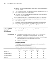
.... Pre-requisites ■ A workstation running a suitable operating system - 50 CHAPTER 3: SETTING UP FOR MANAGEMENT If you do this section assumes the unit has been powered up your Switch manually you can disconnect the serial cable and close the terminal emulator software. refer to "Choosing a Browser... To do not intend to use the command line interface via the console port to manage the Switch, you will need to have the following so that you can manually set up the Switch with RJ-45 connectors at both ends. ■ A suitable Web browser - The procedure described in standalone...
.... Pre-requisites ■ A workstation running a suitable operating system - 50 CHAPTER 3: SETTING UP FOR MANAGEMENT If you do this section assumes the unit has been powered up your Switch manually you can disconnect the serial cable and close the terminal emulator software. refer to "Choosing a Browser... To do not intend to use the command line interface via the console port to manage the Switch, you will need to have the following so that you can manually set up the Switch with RJ-45 connectors at both ends. ■ A suitable Web browser - The procedure described in standalone...

Getting Started Guide
Page 51
b Connect the RJ-45 connector at the other unconfigured Switch. Using the Web Interface 1 Power-up the Switch with IP information. If you have logged on the Switch. This takes approximately one minute. 2 Open a suitable Web browser and enter the IP address of your user name and...Web interface or the command line interface (CLI) via a Front Panel Port Switch Workstation (with a Network Interface Card installed) Ethernet Cable To connect the cable: Front Panel Port Connection a Attach an RJ-45 connector at the password prompt (default user name and password) press Return again....
b Connect the RJ-45 connector at the other unconfigured Switch. Using the Web Interface 1 Power-up the Switch with IP information. If you have logged on the Switch. This takes approximately one minute. 2 Open a suitable Web browser and enter the IP address of your user name and...Web interface or the command line interface (CLI) via a Front Panel Port Switch Workstation (with a Network Interface Card installed) Ethernet Cable To connect the cable: Front Panel Port Connection a Attach an RJ-45 connector at the password prompt (default user name and password) press Return again....
Getting Started Guide
Page 58
... the host key is supplied with RJ-45 connectors. ■ A suitable Web browser. Pre-requisites ■ Ensure you can set up web interface management over the network. 58 CHAPTER 3: SETTING UP FOR MANAGEMENT 5 Open an SSH session and access the Switch using SSH for the device. 6 The Switch and the SSH client will authenticate each...
... the host key is supplied with RJ-45 connectors. ■ A suitable Web browser. Pre-requisites ■ Ensure you can set up web interface management over the network. 58 CHAPTER 3: SETTING UP FOR MANAGEMENT 5 Open an SSH session and access the Switch using SSH for the device. 6 The Switch and the SSH client will authenticate each...

Getting Started Guide
Page 69
... The monitoring system polls the fan status at the auto-negotiation end) Solving Hardware Problems In the rare event of your Switch unit experiencing a hardware failure, refer to the management workstation. ■ Command Line Interface - if configured, an RMON trap is powered up. For more detailed information about ... used (cross-over or straight) Auto-negotiation problems will occur with fiber if: ■ The Receiver (RX) and Transceiver (TX) cable connectors are swapped ■ Fibers are not obstructed. In addition all Summary tables turn red to the CLI. an indication of the...
... The monitoring system polls the fan status at the auto-negotiation end) Solving Hardware Problems In the rare event of your Switch unit experiencing a hardware failure, refer to the management workstation. ■ Command Line Interface - if configured, an RMON trap is powered up. For more detailed information about ... used (cross-over or straight) Auto-negotiation problems will occur with fiber if: ■ The Receiver (RX) and Transceiver (TX) cable connectors are swapped ■ Fibers are not obstructed. In addition all Summary tables turn red to the CLI. an indication of the...

Getting Started Guide
Page 93
.... The conditions are of type H03VVF3GO.75 (minimum). WARNING: The socket outlet must comply with an EN60320/IEC320 appliance inlet. WARNING: The appliance coupler (the connector to the unit and not the wall plug) must have a rated current capacity of at least 10A. ■ The attachment plug must be an earth...
.... The conditions are of type H03VVF3GO.75 (minimum). WARNING: The socket outlet must comply with an EN60320/IEC320 appliance inlet. WARNING: The appliance coupler (the connector to the unit and not the wall plug) must have a rated current capacity of at least 10A. ■ The attachment plug must be an earth...

Getting Started Guide
Page 94
These are powered on. Only connect RJ-45 data connectors, network telephony systems, or network telephones to a traditional PBX or public telephone ... when they are shielded RJ-45 data sockets. This can be connected to the console port of the Switch 4500, only use a modem which is powered on the rear of the Redundant Power Supply (RPS) should only... be read in accordance with your RPS. They cannot be earthed (grounded). WARNING: When powering any Switch 4500 from the RPS. It must be ensured that the earth connection is made before connecting the DC supply from...
These are powered on. Only connect RJ-45 data connectors, network telephony systems, or network telephones to a traditional PBX or public telephone ... when they are shielded RJ-45 data sockets. This can be connected to the console port of the Switch 4500, only use a modem which is powered on the rear of the Redundant Power Supply (RPS) should only... be read in accordance with your RPS. They cannot be earthed (grounded). WARNING: When powering any Switch 4500 from the RPS. It must be ensured that the earth connection is made before connecting the DC supply from...

Getting Started Guide
Page 95
...troites. L'information de Sécurité Importante 95 WARNING: The characteristics of the Switch 4500 DC supply input are given in Appendix C on all front ports. WARNING: Ensure that the negative terminal on the Switch is in the RPS is connected to the negative (circuit breaker) terminal of the ...RPS and that the circuit breaker in the open (off) position when connecting the cable to the RPS and the cable and connector to the Switch. L'information de Sécurité Importante AVERTISSEMENT: L'installation et la dépose de ce groupe doivent être confiés &#...
...troites. L'information de Sécurité Importante 95 WARNING: The characteristics of the Switch 4500 DC supply input are given in Appendix C on all front ports. WARNING: Ensure that the negative terminal on the Switch is in the RPS is connected to the negative (circuit breaker) terminal of the ...RPS and that the circuit breaker in the open (off) position when connecting the cable to the RPS and the cable and connector to the Switch. L'information de Sécurité Importante AVERTISSEMENT: L'installation et la dépose de ce groupe doivent être confiés &#...

Getting Started Guide
Page 111
B PIN-OUTS Null Modem Cable RJ-45 to RS-232 25-pin Switch 4500 Cable connector: RJ-45 female Screen Shell TxD 3 RxD 2 Ground 5 RTS 7 CTS 8 DSR 6 DCD 1 DTR 4 PC/Terminal Cable connector: 25-pin male/female 1 Screen only required if screen 3 RxD 2 TxD always required 7...handshake 6 DSR 8 DCD PC-AT Serial Cable RJ-45 to 9-pin Switch 4500 Cable connector: RJ-45 female Screen Shell DTR 4 TxD 3 RxD 2 CTS 8 Ground 5 DSR 6 RTS 7 DCD 1 PC-AT Serial Port Cable connector: 9-pin female Shell Screen only required if screen 1 DCD Required for handshake...
B PIN-OUTS Null Modem Cable RJ-45 to RS-232 25-pin Switch 4500 Cable connector: RJ-45 female Screen Shell TxD 3 RxD 2 Ground 5 RTS 7 CTS 8 DSR 6 DCD 1 DTR 4 PC/Terminal Cable connector: 25-pin male/female 1 Screen only required if screen 3 RxD 2 TxD always required 7...handshake 6 DSR 8 DCD PC-AT Serial Cable RJ-45 to 9-pin Switch 4500 Cable connector: RJ-45 female Screen Shell DTR 4 TxD 3 RxD 2 CTS 8 Ground 5 DSR 6 RTS 7 DCD 1 PC-AT Serial Port Cable connector: 9-pin female Shell Screen only required if screen 1 DCD Required for handshake...

Getting Started Guide
Page 112
... RJ-45 to RS-232 25-pin Switch 4500 Cable connector: RJ-45 female Screen Shell TxD 3 RxD 2 RTS 7 CTS 8 DSR 6 Ground 5 DCD 1 DTR 4 RS-232 Modem Port Cable connector: 25-pin male 1 Screen 2 TxD 3 RxD 4 RTS 5 CTS 6 DSR 7 Ground 8 DCD 20 DTR Ethernet Port RJ-45 Pin Assignments 10/100 and 1000BASE-T RJ-45 connections.
... RJ-45 to RS-232 25-pin Switch 4500 Cable connector: RJ-45 female Screen Shell TxD 3 RxD 2 RTS 7 CTS 8 DSR 6 Ground 5 DCD 1 DTR 4 RS-232 Modem Port Cable connector: 25-pin male 1 Screen 2 TxD 3 RxD 4 RTS 5 CTS 6 DSR 7 Ground 8 DCD 20 DTR Ethernet Port RJ-45 Pin Assignments 10/100 and 1000BASE-T RJ-45 connections.