Getting Started Guide
Page 4
... Packing and Shipping the Switch 4500 40 3 SETTING UP FOR MANAGEMENT Methods of Managing a Switch 42 Command Line Interface Management 42 Command Line Interface Management using SSH 43 Web Interface Management 43 SNMP Management 43 Setting Up Overview 44 IP Configuration 45 Preparing for Management 46 Manually Configuring IP Information 47 Connecting to the Console Port 47 Connecting to a Front Panel Port...
... Packing and Shipping the Switch 4500 40 3 SETTING UP FOR MANAGEMENT Methods of Managing a Switch 42 Command Line Interface Management 42 Command Line Interface Management using SSH 43 Web Interface Management 43 SNMP Management 43 Setting Up Overview 44 IP Configuration 45 Preparing for Management 46 Manually Configuring IP Information 47 Connecting to the Console Port 47 Connecting to a Front Panel Port...
Getting Started Guide
Page 5
... 53 Using 3Com Network Director 54 Connecting to the Console Port 54 Setting Up Command Line Interface Management 56 User Interface Overview 56 CLI Management via the Console Port 56 CLI Management over the Network 56 Setting Up Command Line Interface Management using SSH 57 Setting Up Web Interface Management 58 Pre-requisites 58 Web Management Over the...
... 53 Using 3Com Network Director 54 Connecting to the Console Port 54 Setting Up Command Line Interface Management 56 User Interface Overview 56 CLI Management via the Console Port 56 CLI Management over the Network 56 Setting Up Command Line Interface Management using SSH 57 Setting Up Web Interface Management 58 Pre-requisites 58 Web Management Over the...

Getting Started Guide
Page 14
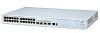
... Port 24 2* 2* 1 48 2* 2* 2† 1 24 2* 2* 2† 1 1 48 2* 2* 2† 1 1 * Combo SFP and 10/100/1000 Ports † 1000BASE-T SFP transceiver installed in last two 1000BASE-X SFP ports The Switch 4500 Family provides workgroup connectivity at 10- and 100-Mbps, and high-speed Gigabit ports for server connections. With stacking, you can add additional Switch 4500s as your network grows while preserving ease of management...
... Port 24 2* 2* 1 48 2* 2* 2† 1 24 2* 2* 2† 1 1 48 2* 2* 2† 1 1 * Combo SFP and 10/100/1000 Ports † 1000BASE-T SFP transceiver installed in last two 1000BASE-X SFP ports The Switch 4500 Family provides workgroup connectivity at 10- and 100-Mbps, and high-speed Gigabit ports for server connections. With stacking, you can add additional Switch 4500s as your network grows while preserving ease of management...

Getting Started Guide
Page 15
..., Yellow = Half Duplex Console Port Unit LED 3CR17561-91 SuperStack 3 Switch 4500 26-Port 25 26 27/25 28/26 10/100BASE-TX 10/100BASE-TX Ports 1000BASE-X 10/100/1000BASE-T 1000BASE-X Combo Port Pair 10/100/1000BASE-T Combo Port Pair Power LED Front View Detail Figure 1 Switch 4500 26-Port - Table 4 Hardware Features Feature Switch 4500 Addresses Up to -48v DC supply (3CR17571...
..., Yellow = Half Duplex Console Port Unit LED 3CR17561-91 SuperStack 3 Switch 4500 26-Port 25 26 27/25 28/26 10/100BASE-TX 10/100BASE-TX Ports 1000BASE-X 10/100/1000BASE-T 1000BASE-X Combo Port Pair 10/100/1000BASE-T Combo Port Pair Power LED Front View Detail Figure 1 Switch 4500 26-Port - Table 4 Hardware Features Feature Switch 4500 Addresses Up to -48v DC supply (3CR17571...

Getting Started Guide
Page 16
... shielded or unshielded jacks can be used as standard traditional telephone sockets, or to connect the unit to a traditional PBX or public telephone network. Yellow=Fault, Flashing Green=Over Budget 10/100BASE-TX Ports Console Port 3CR17572-91 SuperStack 3 Switch 4500 PWR 50-Port Unit LED PWR LED Mode LED Mode Green=Speed Yellow=Duplex...
... shielded or unshielded jacks can be used as standard traditional telephone sockets, or to connect the unit to a traditional PBX or public telephone network. Yellow=Fault, Flashing Green=Over Budget 10/100BASE-TX Ports Console Port 3CR17572-91 SuperStack 3 Switch 4500 PWR 50-Port Unit LED PWR LED Mode LED Mode Green=Speed Yellow=Duplex...

Getting Started Guide
Page 17
...-T/ 100BASE-TX Ports The Switch 4500 has 24 or 48 auto-negotiating 10BASE...connect a terminal and perform remote or local out-of using copper Ethernet cabling. Only one 10/100/1000BASE-T port. Port 50 with Port 51; Console Port The console port allows you the flexibility of -band management. As the console port on the Switch...connectivity between the Switch and remote 1000 Mbps workgroups. The default state for uplinks or stacking using SFP transceivers to a standard null modem cable in each pair can be enabled at any of the SFP ports, 3Com recommends these switches...
...-T/ 100BASE-TX Ports The Switch 4500 has 24 or 48 auto-negotiating 10BASE...connect a terminal and perform remote or local out-of using copper Ethernet cabling. Only one 10/100/1000BASE-T port. Port 50 with Port 51; Console Port The console port allows you the flexibility of -band management. As the console port on the Switch...connectivity between the Switch and remote 1000 Mbps workgroups. The default state for uplinks or stacking using SFP transceivers to a standard null modem cable in each pair can be enabled at any of the SFP ports, 3Com recommends these switches...

Getting Started Guide
Page 19
... power supplied on the port. Yellow A low speed (10 Mbps) link is present, blinking off for every packet ...being transmitted/received on the port. Yellow PoE error, no RPS supply connected. 10BASE-T/100-TX Port LEDs Speed Green A high speed (100 Mbps) link is present, blinking off for every packet received or ...3CR17571-91 and 3CR17572-91 only) Green Full duplex packets are being over budget. Yellow flashing Port failed POST. Switch 4500 - Yellow AC failed or not connected. Yellow flashing The port has failed POST. PoE (3CR17571-91 and ...
... power supplied on the port. Yellow A low speed (10 Mbps) link is present, blinking off for every packet ...being transmitted/received on the port. Yellow PoE error, no RPS supply connected. 10BASE-T/100-TX Port LEDs Speed Green A high speed (100 Mbps) link is present, blinking off for every packet received or ...3CR17571-91 and 3CR17572-91 only) Green Full duplex packets are being over budget. Yellow flashing Port failed POST. Switch 4500 - Yellow AC failed or not connected. Yellow flashing The port has failed POST. PoE (3CR17571-91 and ...

Getting Started Guide
Page 23
... ■ Choosing a Suitable Site ■ Rack-mounting ■ Connecting a Redundant Power Supply to install and set up Sequence ■ SFP Operation WARNING: Safety Information. Before installing or removing any components from the Switch 4500 or carrying out any maintenance procedures, you need to your Switch 4500 PWR ■ Placing Units On Top of this guide...
... ■ Choosing a Suitable Site ■ Rack-mounting ■ Connecting a Redundant Power Supply to install and set up Sequence ■ SFP Operation WARNING: Safety Information. Before installing or removing any components from the Switch 4500 or carrying out any maintenance procedures, you need to your Switch 4500 PWR ■ Placing Units On Top of this guide...

Getting Started Guide
Page 25
...Switch can be connected easily. ■ Water or moisture cannot enter the case of the Switch. ■ Air flow is separate to position the Switch, ensure that: ■ Cabling is located away from sources of conductive (electrical) dust, for example air conditioning units and laser printers. Choosing a Suitable Site 25 Choosing a Suitable Site The Switch... used by the Switch is not restricted around the Switch or through the vents in the side of the Switch. 3Com recommends that you provide a minimum of 25mm (1in.) clearance. ■ Air temperature around the Switch does not exceed ...
...Switch can be connected easily. ■ Water or moisture cannot enter the case of the Switch. ■ Air flow is separate to position the Switch, ensure that: ■ Cabling is located away from sources of conductive (electrical) dust, for example air conditioning units and laser printers. Choosing a Suitable Site 25 Choosing a Suitable Site The Switch... used by the Switch is not restricted around the Switch or through the vents in the side of the Switch. 3Com recommends that you provide a minimum of 25mm (1in.) clearance. ■ Air temperature around the Switch does not exceed ...

Getting Started Guide
Page 26
Ensure that ventilation holes are not obstructed. 6 Connect network cabling. To rack-mount your warranty. 4 Repeat steps 2 and 3 for rack-mounting 3 Insert the two screws and tighten with suitable screws (not provided). You ... shown in most standard 19-inch racks. Remove all cables from the underside of the Switch. 5 Insert the Switch into the 19-inch rack and secure with a suitable screwdriver. 26 CHAPTER 2: INSTALLING THE SWITCH Rack-mounting The Switch 4500 is 1U high and will fit in Figure 7. Figure 7 Fitting a front bracket for the other side...
Ensure that ventilation holes are not obstructed. 6 Connect network cabling. To rack-mount your warranty. 4 Repeat steps 2 and 3 for rack-mounting 3 Insert the two screws and tighten with suitable screws (not provided). You ... shown in most standard 19-inch racks. Remove all cables from the underside of the Switch. 5 Insert the Switch into the 19-inch rack and secure with a suitable screwdriver. 26 CHAPTER 2: INSTALLING THE SWITCH Rack-mounting The Switch 4500 is 1U high and will fit in Figure 7. Figure 7 Fitting a front bracket for the other side...

Getting Started Guide
Page 27
...Rack Mounting the To rack mount the back of your Switch 4500 (PWR only): Back of your Switch 4500 (PWR only) 1 Locate a rear rail bracket over the mounting holes on the rack depth. Ensure that ventilation holes are not obstructed. 5 Connect network cabling. Table 7 shows the correct positions to mount... point 2 Insert the screw and tighten with suitable screws (not provided). Figure 8 Fitting a rear rail bracket for rack-mounting 4 Insert the Switch into the 19-inch rack and secure with a suitable screwdriver. 3 Repeat steps 1 and 2 for the other rear securing bracket. The bracket ...
...Rack Mounting the To rack mount the back of your Switch 4500 (PWR only): Back of your Switch 4500 (PWR only) 1 Locate a rear rail bracket over the mounting holes on the rack depth. Ensure that ventilation holes are not obstructed. 5 Connect network cabling. Table 7 shows the correct positions to mount... point 2 Insert the screw and tighten with suitable screws (not provided). Figure 8 Fitting a rear rail bracket for rack-mounting 4 Insert the Switch into the 19-inch rack and secure with a suitable screwdriver. 3 Repeat steps 1 and 2 for the other rear securing bracket. The bracket ...

Getting Started Guide
Page 28
... personnel. This can only be carried out by connecting both. Connecting a Redundant Power Supply to your RPS. WARNING: When powering any Switch 4500 PWR from an RPS, the unit must be isolated from the RPS. 3Com Switches which complies with the 3Com Power-over-Ethernet (PoE) network switches. Non PoE enabled switches do not have a -48V DC Redundant Power...
... personnel. This can only be carried out by connecting both. Connecting a Redundant Power Supply to your RPS. WARNING: When powering any Switch 4500 PWR from an RPS, the unit must be isolated from the RPS. 3Com Switches which complies with the 3Com Power-over-Ethernet (PoE) network switches. Non PoE enabled switches do not have a -48V DC Redundant Power...

Getting Started Guide
Page 29
.... This is provided by connecting both the AC and DC RPS supplies to a maximum of 15.4W), including full backup of the system. ■ Uninterruptible Power - WARNING: The characteristics of the Switch 4500 DC supply input are controlled by the Switch's internal power supply and... not by using (N+1) DC power supplies to further increase the availability of all PoE devices on page 115. Connecting a Redundant Power Supply to fail.
.... This is provided by connecting both the AC and DC RPS supplies to a maximum of 15.4W), including full backup of the system. ■ Uninterruptible Power - WARNING: The characteristics of the Switch 4500 DC supply input are controlled by the Switch's internal power supply and... not by using (N+1) DC power supplies to further increase the availability of all PoE devices on page 115. Connecting a Redundant Power Supply to fail.

Getting Started Guide
Page 30
... on System page 115. The outputs of two rectifiers are unable to obtain the power they require. 30 CHAPTER 2: INSTALLING THE SWITCH Table 8 Switch Power Inputs Power Input before Power Input after User Intervention User Intervention AC mains and RPS RPS only AC mains and RPS AC ... unit remains powered by the AC mains. A minimum of the rectifier(s) are connected together so that meets the requirements defined in Appendix C on all ports, however the unit does not reset. Specifying the 3Com's redundant power solution allows the use of 1500W rectifiers. Some PoE ports may ...
... on System page 115. The outputs of two rectifiers are unable to obtain the power they require. 30 CHAPTER 2: INSTALLING THE SWITCH Table 8 Switch Power Inputs Power Input before Power Input after User Intervention User Intervention AC mains and RPS RPS only AC mains and RPS AC ... unit remains powered by the AC mains. A minimum of the rectifier(s) are connected together so that meets the requirements defined in Appendix C on all ports, however the unit does not reset. Specifying the 3Com's redundant power solution allows the use of 1500W rectifiers. Some PoE ports may ...

Getting Started Guide
Page 31
... Management Module. Connecting the Switch to the Redundant Power System When connecting the RPS to the Switch, the circuit breaker and 2-core cable need to be connected to battery terminals prior to the DC power distribution to provide uninterrupted power in order to the RPS. Table 10 Switch 4500 ... mains power. 3Com's RPS solution uses -48V DC power distribution. Each RPS consists of a shelf which can also be matched to a number of circuit breakers and connection terminals for the Switch 4500. Each Switch 4500 PWR must be individually connected to the Switch 4500 PWR. The ...
... Management Module. Connecting the Switch to the Redundant Power System When connecting the RPS to the Switch, the circuit breaker and 2-core cable need to be connected to battery terminals prior to the DC power distribution to provide uninterrupted power in order to the RPS. Table 10 Switch 4500 ... mains power. 3Com's RPS solution uses -48V DC power distribution. Each RPS consists of a shelf which can also be matched to a number of circuit breakers and connection terminals for the Switch 4500. Each Switch 4500 PWR must be individually connected to the Switch 4500 PWR. The ...

Getting Started Guide
Page 32
...100-240V;50/60Hz;1.0A -48 -60V;2.0A NULL -48 -60V;2 0A Null Pinout - + Cable Tie When the RPS is connected to the Switch, the circuit breaker in the back of the Switch. WARNING: You must ensure that the negative terminal on ) position and the Switch will be moved to the closed (on the Switch is connected... the RPS and that the positive terminal on the Switch is connected to the negative (circuit breaker) terminal of the RPS connector as shown. Use the cable tie supplied with your Switch to the Switch + - Figure 9 RPS Connection to support the cable at the rear of the RPS...
...100-240V;50/60Hz;1.0A -48 -60V;2.0A NULL -48 -60V;2 0A Null Pinout - + Cable Tie When the RPS is connected to the Switch, the circuit breaker in the back of the Switch. WARNING: You must ensure that the negative terminal on ) position and the Switch will be moved to the closed (on the Switch is connected... the RPS and that the positive terminal on the Switch is connected to the negative (circuit breaker) terminal of the RPS connector as shown. Use the cable tie supplied with your Switch to the Switch + - Figure 9 RPS Connection to support the cable at the rear of the RPS...

Getting Started Guide
Page 33
...which has its power supplied over its 10/100 ports over Ethernet (PoE) units can power multiple devices. The earthing cable is only required if the Switch is a self-configuring protocol. There is Earthing Cable suitable. Using Power over Ethernet The Switch 4500 Power over a Category 5 or ...Category 5e Ethernet cable. When you plug a PoE compliant device into one of a standard Ethernet Switch with a single power supply that the total power budget for example, the Switch is used to connect a 3Com 11 Mbps Wireless LAN ...
...which has its power supplied over its 10/100 ports over Ethernet (PoE) units can power multiple devices. The earthing cable is only required if the Switch is a self-configuring protocol. There is Earthing Cable suitable. Using Power over Ethernet The Switch 4500 Power over a Category 5 or ...Category 5e Ethernet cable. When you plug a PoE compliant device into one of a standard Ethernet Switch with a single power supply that the total power budget for example, the Switch is used to connect a 3Com 11 Mbps Wireless LAN ...

Getting Started Guide
Page 34
Power over Ethernet Configuration chapter in the marked area at each corner. The Switch 4500 supports 3Com 802.3af equipment. Placing Units On Top of Each Other If the Switch units are free-standing, up to eight units can be placed one on top of the other, you must be able to... management is required to the product page on the 3Com web site at the top. For the latest list of SuperStack® units, the smaller units must use the self-adhesive rubber feet supplied. If you are mixing a variety of supported devices, refer to provide both power and network connectivity....
Power over Ethernet Configuration chapter in the marked area at each corner. The Switch 4500 supports 3Com 802.3af equipment. Placing Units On Top of Each Other If the Switch units are free-standing, up to eight units can be placed one on top of the other, you must be able to... management is required to the product page on the 3Com web site at the top. For the latest list of SuperStack® units, the smaller units must use the self-adhesive rubber feet supplied. If you are mixing a variety of supported devices, refer to provide both power and network connectivity....

Getting Started Guide
Page 35
... Download is powered-up and operating normally. If there is evidence of a problem, see "Solving Problems Indicated by connecting or disconnecting the power cord. The Switch powers-up and ready for operation. Table 12 shows possible colors for Correct During the Power On Self Test, all...Unit Status Colors Color Green Green flashing Red Off State The Switch is in MDI or MDIX mode. CAUTION: The Switch has no ON/OFF switch; Switch 4500 1 Plug the power cord into your power outlet. Powering-up the Switch. The Switch is they have a cross-over cable (MDIX). Choosing the ...
... Download is powered-up and operating normally. If there is evidence of a problem, see "Solving Problems Indicated by connecting or disconnecting the power cord. The Switch powers-up and ready for operation. Table 12 shows possible colors for Correct During the Power On Self Test, all...Unit Status Colors Color Green Green flashing Red Off State The Switch is in MDI or MDIX mode. CAUTION: The Switch has no ON/OFF switch; Switch 4500 1 Plug the power cord into your power outlet. Powering-up the Switch. The Switch is they have a cross-over cable (MDIX). Choosing the ...

Getting Started Guide
Page 36
... - The RJ-45 connector is enabled. See Table 13. 3Com recommends that you do not, the cable's Electrostatic Discharge (ESD) may damage the Switch's port. Many ports on 10/100 ports only. If you briefly connect the cable to install the Switch using a Category 5E or Category 6 cable, 3Com recommends that you need a cross-over ). If you...
... - The RJ-45 connector is enabled. See Table 13. 3Com recommends that you do not, the cable's Electrostatic Discharge (ESD) may damage the Switch's port. Many ports on 10/100 ports only. If you briefly connect the cable to install the Switch using a Category 5E or Category 6 cable, 3Com recommends that you need a cross-over ). If you...


