
Getting Started Guide
Page 18
...LED (seven segment display). Green flashing The Switch has failed POST. Mode LED (3CR17571-91 and 3CR17572-91 only) Speed Green 10/100 Port Speed and Activity, 1000 SFP Status and Activity, or Stack Status and Activity. Table 5 LED Behavior LED Color Indicates Unit LED Green Power On Self Test...diagnose the problem. The Unit LED flashes the number of the Switch. Yellow flashing One or more ports have failed POST. During POST a the test ID number appears in progress. 18 CHAPTER 1: INTRODUCING THE SWITCH 4500 FAMILY Unit LED The Unit LED is critical. Green flashing ...
...LED (seven segment display). Green flashing The Switch has failed POST. Mode LED (3CR17571-91 and 3CR17572-91 only) Speed Green 10/100 Port Speed and Activity, 1000 SFP Status and Activity, or Stack Status and Activity. Table 5 LED Behavior LED Color Indicates Unit LED Green Power On Self Test...diagnose the problem. The Unit LED flashes the number of the Switch. Yellow flashing One or more ports have failed POST. During POST a the test ID number appears in progress. 18 CHAPTER 1: INTRODUCING THE SWITCH 4500 FAMILY Unit LED The Unit LED is critical. Green flashing ...

Getting Started Guide
Page 19
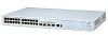
...has failed POST. Yellow PoE error, no RPS supply connected. 10BASE-T/100-TX Port LEDs Speed Green A high speed (100 Mbps) link is present, blinking off for every packet received or... present. Off No link is present. Front View Detail 19 LED Color Indicates RPS LED (3CR17571-91 and 3CR17572-91 only) Green AC and RPS supply connected. Yellow Flashing The port ...PoE (3CR17571-91 and 3CR171572 only) Green Power is being transmitted/received on the port. RPS supply is unable to supply power due to the port. Switch 4500 - Yellow A low speed (10 Mbps) link...
...has failed POST. Yellow PoE error, no RPS supply connected. 10BASE-T/100-TX Port LEDs Speed Green A high speed (100 Mbps) link is present, blinking off for every packet received or... present. Off No link is present. Front View Detail 19 LED Color Indicates RPS LED (3CR17571-91 and 3CR17572-91 only) Green AC and RPS supply connected. Yellow Flashing The port ...PoE (3CR17571-91 and 3CR171572 only) Green Power is being transmitted/received on the port. RPS supply is unable to supply power due to the port. Switch 4500 - Yellow A low speed (10 Mbps) link...

Getting Started Guide
Page 33
...LED Colors Color Green Yellow Off State AC and RPS supply connected. The same cable connects the device to the network. Using a PoE Switch has the following advantages over Ethernet is a self-configuring protocol. Connecting the Use the earthing cable that accompanies your Switch 4500 PWR...) compliant device which has its power supplied over its 10/100 ports over a Category 5 or Category 5e Ethernet cable. Connecting a Redundant Power Supply to your Switch if the length is ok. Using Power over Ethernet The Switch 4500 Power over Ethernet (PoE) units can power multiple devices...
...LED Colors Color Green Yellow Off State AC and RPS supply connected. The same cable connects the device to the network. Using a PoE Switch has the following advantages over Ethernet is a self-configuring protocol. Connecting the Use the earthing cable that accompanies your Switch 4500 PWR...) compliant device which has its power supplied over its 10/100 ports over a Category 5 or Category 5e Ethernet cable. Connecting a Redundant Power Supply to your Switch if the length is ok. Using Power over Ethernet The Switch 4500 Power over Ethernet (PoE) units can power multiple devices...

Getting Started Guide
Page 35
...the Correct Cables All of the ports on the Switch are disabled and Operation of LEDs the LEDs light. Switch 4500 1 Plug the power cord into the power socket at the rear of the Switch. 2 Plug the other end of the power cord into your Switch 4500 powered-up and ready for a list of ... the Power On Self Test, all ports on page 68 for operation. Table 12 Unit Status Colors Color Green Green flashing Red Off State The Switch is by LEDs" on the Switch are Auto-MDIX, that your Switch is operating correctly. the only method of a problem, see "Solving Problems Indicated by connecting or...
...the Correct Cables All of the ports on the Switch are disabled and Operation of LEDs the LEDs light. Switch 4500 1 Plug the power cord into the power socket at the rear of the Switch. 2 Plug the other end of the power cord into your Switch 4500 powered-up and ready for a list of ... the Power On Self Test, all ports on page 68 for operation. Table 12 Unit Status Colors Color Green Green flashing Red Off State The Switch is by LEDs" on the Switch are Auto-MDIX, that your Switch is operating correctly. the only method of a problem, see "Solving Problems Indicated by connecting or...