
Getting Started Guide
Page 2
...we are labelled according to make changes in all operations. Conserving energy, materials and natural resources in content from sustainable, managed forests; Maximizing the recyclable and reusable content of safely. Ensuring that all products can be provided to you in conjunction ... FAR 2.101(a) and as are commercial in the United States and other countries, licensed exclusively through X/Open Company, Ltd. UNIX is a registered trademark of 3Com Corporation to be trademarks of Microsoft Corporation. Netscape Navigator is a registered trademark in nature and developed solely...
...we are labelled according to make changes in all operations. Conserving energy, materials and natural resources in content from sustainable, managed forests; Maximizing the recyclable and reusable content of safely. Ensuring that all products can be provided to you in conjunction ... FAR 2.101(a) and as are commercial in the United States and other countries, licensed exclusively through X/Open Company, Ltd. UNIX is a registered trademark of 3Com Corporation to be trademarks of Microsoft Corporation. Netscape Navigator is a registered trademark in nature and developed solely...

Getting Started Guide
Page 3
Rear View Detail 20 Power Socket 20 Open Book Warning Labels 20 Redundant Power System Socket 21 Default Settings 21 CONTENTS ABOUT THIS GUIDE Before You Start 9 Release Notes 9 About Your CD-ROM 10 Conventions 10 Related Documentation 11 Accessing Online Documentation 12 Documentation Comments 12 1 INTRODUCING THE SWITCH 4500 FAMILY About the Switch 4500 14 Summary of Hardware Features 15 Switch 4500 - Front View Detail 15 10BASE-T/ 100BASE-TX Ports 17 Gigabit Ports 17 Console Port 17 Unit LED 18 LEDs 18 Switch 4500 -
Rear View Detail 20 Power Socket 20 Open Book Warning Labels 20 Redundant Power System Socket 21 Default Settings 21 CONTENTS ABOUT THIS GUIDE Before You Start 9 Release Notes 9 About Your CD-ROM 10 Conventions 10 Related Documentation 11 Accessing Online Documentation 12 Documentation Comments 12 1 INTRODUCING THE SWITCH 4500 FAMILY About the Switch 4500 14 Summary of Hardware Features 15 Switch 4500 - Front View Detail 15 10BASE-T/ 100BASE-TX Ports 17 Gigabit Ports 17 Console Port 17 Unit LED 18 LEDs 18 Switch 4500 -

Getting Started Guide
Page 20
... instalar o extraer cualquier componente del Switch 4500 Family o de realizar tareas de mantenimiento, debe leer la información de seguridad facilitada en el Apéndice A de esta guía. rear view Open Book Warning Labels Earthing Screw NULL ~100-240V; 50/60Hz; 7.0A -53..., you must read the safety information provided in the range 100-240 VAC. rear view Open Book Warning Labels ~100-240V; 50/60Hz; 1A Power Socket Figure 6 Switch 4500 PWR - VORSICHT:Bevor Sie Komponenten der Switch 4500-Baureihe installieren oder deinstallieren und bevor Sie Wartungsarbeiten ausführen...
... instalar o extraer cualquier componente del Switch 4500 Family o de realizar tareas de mantenimiento, debe leer la información de seguridad facilitada en el Apéndice A de esta guía. rear view Open Book Warning Labels Earthing Screw NULL ~100-240V; 50/60Hz; 7.0A -53..., you must read the safety information provided in the range 100-240 VAC. rear view Open Book Warning Labels ~100-240V; 50/60Hz; 1A Power Socket Figure 6 Switch 4500 PWR - VORSICHT:Bevor Sie Komponenten der Switch 4500-Baureihe installieren oder deinstallieren und bevor Sie Wartungsarbeiten ausführen...

Getting Started Guide
Page 32
... ~100-240V;50/60Hz;1.0A -48 -60V;2.0A NULL -48 -60V;2 0A Null Pinout - + Cable Tie When the RPS is connected to the Switch, the circuit breaker in the back of the RPS. 32 CHAPTER 2: INSTALLING THE SWITCH WARNING: Ensure that the negative terminal on ) position and the Switch will be moved to the Switch...) terminal of the RPS and that the circuit breaker in the RPS is in the open (off) position when connecting the cable to the RPS and the cable and connector to the closed (on the Switch is connected to the RPS socket in the RPS can be powered by the -48V DC...
... ~100-240V;50/60Hz;1.0A -48 -60V;2.0A NULL -48 -60V;2 0A Null Pinout - + Cable Tie When the RPS is connected to the Switch, the circuit breaker in the back of the RPS. 32 CHAPTER 2: INSTALLING THE SWITCH WARNING: Ensure that the negative terminal on ) position and the Switch will be moved to the Switch...) terminal of the RPS and that the circuit breaker in the RPS is in the open (off) position when connecting the cable to the RPS and the cable and connector to the closed (on the Switch is connected to the RPS socket in the RPS can be powered by the -48V DC...

Getting Started Guide
Page 48
... times until it from being loosened. 2 Open your terminal emulation software and configure the COM port settings to the workstation and tighten the retaining screws on Self Test (POST) will now be set up the Switch. 48 CHAPTER 3: SETTING UP FOR MANAGEMENT Connecting the Workstation to the Switch 1 Connect the workstation to the documentation...
... times until it from being loosened. 2 Open your terminal emulation software and configure the COM port settings to the workstation and tighten the retaining screws on Self Test (POST) will now be set up the Switch. 48 CHAPTER 3: SETTING UP FOR MANAGEMENT Connecting the Workstation to the Switch 1 Connect the workstation to the documentation...

Getting Started Guide
Page 51
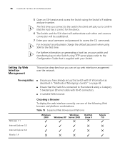
This takes approximately one minute. 2 Open a suitable Web browser and enter the IP address of your user name and press Return and at the other unconfigured Switch. Setting Up the Switch with IP Information You are now ready to manually set up the Switch with a Network Interface Card installed) ...end of the Ethernet cable to the Network Interface Card (NIC) in the workstation. If you have logged on the Switch. Figure 19 Connecting a Workstation to the Switch via telnet. b Connect the RJ-45 connector at the password prompt (default user name and password) press Return again....
This takes approximately one minute. 2 Open a suitable Web browser and enter the IP address of your user name and press Return and at the other unconfigured Switch. Setting Up the Switch with IP Information You are now ready to manually set up the Switch with a Network Interface Card installed) ...end of the Ethernet cable to the Network Interface Card (NIC) in the workstation. If you have logged on the Switch. Figure 19 Connecting a Workstation to the Switch via telnet. b Connect the RJ-45 connector at the password prompt (default user name and password) press Return again....

Getting Started Guide
Page 52
... to the unit, click Start in Figure 20. See "Methods of Managing a Switch" on correctly, is the IP address of the Switch) c Click OK. 2 Press Enter to open a login prompt. 52 CHAPTER 3: SETTING UP FOR MANAGEMENT 4 To enter basic setup information for you want the Switch to use when it starts. 3 At the login and password...
... to the unit, click Start in Figure 20. See "Methods of Managing a Switch" on correctly, is the IP address of the Switch) c Click OK. 2 Press Enter to open a login prompt. 52 CHAPTER 3: SETTING UP FOR MANAGEMENT 4 To enter basic setup information for you want the Switch to use when it starts. 3 At the login and password...

Getting Started Guide
Page 56
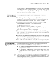
... to the console port correctly as described in "Methods of Managing a Switch" on page 42. 2 Check that you have the IP protocol correctly installed on page 47. 2 Your Switch is powered up to the Switch. CLI Management over To manage a Switch using the command line interface over the network. 56 CHAPTER ... . 4 To open a Telnet session via the DOS prompt, enter the IP address of the Switch that your Switch via its console port. A fabric can browse, the IP protocol is installed. 3 Check you get an error message, check that you wish to continue being managed and/or configured ...
... to the console port correctly as described in "Methods of Managing a Switch" on page 42. 2 Check that you have the IP protocol correctly installed on page 47. 2 Your Switch is powered up to the Switch. CLI Management over To manage a Switch using the command line interface over the network. 56 CHAPTER ... . 4 To open a Telnet session via the DOS prompt, enter the IP address of the Switch that your Switch via its console port. A fabric can browse, the IP protocol is installed. 3 Check you get an error message, check that you wish to continue being managed and/or configured ...

Getting Started Guide
Page 57
...suitable for the first time, or after any reset to factory defaults. Setting Up Command Line Interface Management using SSH 57 (where xxx.xxx.xxx.xxx is the IP address of the Switch) If opening a Telnet session via third party software you will be refused. 4 Install an SSH client application on... the workstation you want to use to access the switch. 3Com recommends the following format: c:\ ping xxx.xxx.xxx.xxx (where...
...suitable for the first time, or after any reset to factory defaults. Setting Up Command Line Interface Management using SSH 57 (where xxx.xxx.xxx.xxx is the IP address of the Switch) If opening a Telnet session via third party software you will be refused. 4 Install an SSH client application on... the workstation you want to use to access the switch. 3Com recommends the following format: c:\ ping xxx.xxx.xxx.xxx (where...
Getting Started Guide
Page 58
... security please change the default password when using the Switch's IP address and port number. The first time you connect to access the CLI commands. 58 CHAPTER 3: SETTING UP FOR MANAGEMENT 5 Open an SSH session and access the Switch using SSH for the device. 6 The Switch and the SSH client will authenticate each other and...
... security please change the default password when using the Switch's IP address and port number. The first time you connect to access the CLI commands. 58 CHAPTER 3: SETTING UP FOR MANAGEMENT 5 Open an SSH session and access the Switch using SSH for the device. 6 The Switch and the SSH client will authenticate each other and...
Getting Started Guide
Page 59
... Bases (MIBs) are installed on the Device View button to enable them if you use the 3Com Network Director application that you wish to manage in the URL locator, for your browser. Web Management To manage a Switch using a port in the following format: c:\ ping xxx.xxx.xxx.xxx (where xxx.xxx.xxx.xxx is the... password prompt (or the password of your choice if you get an error message, check that your IP information has been entered correctly and the Switch is powered up. 3 Open your web browser and enter the IP address of the...
... Bases (MIBs) are installed on the Device View button to enable them if you use the 3Com Network Director application that you wish to manage in the URL locator, for your browser. Web Management To manage a Switch using a port in the following format: c:\ ping xxx.xxx.xxx.xxx (where xxx.xxx.xxx.xxx is the... password prompt (or the password of your choice if you get an error message, check that your IP information has been entered correctly and the Switch is powered up. 3 Open your web browser and enter the IP address of the...

Getting Started Guide
Page 81
...downloading, start the XModem send file process with terminal emulation software, such as Microsoft Hyperterminal. is a slow transfer protocol limited to your Switch via the To upgrade software to the current speed settings of the download no exec input/output will be available! Upgrading from the ...Command Line Interface 81 200 PORT command successful. 150 Opening ASCII mode data connection for each of the remaining files. Before pressing ENTER you must choose 'YES' or 'NO'[Y/N]: 2 Enter y to...
...downloading, start the XModem send file process with terminal emulation software, such as Microsoft Hyperterminal. is a slow transfer protocol limited to your Switch via the To upgrade software to the current speed settings of the download no exec input/output will be available! Upgrading from the ...Command Line Interface 81 200 PORT command successful. 150 Opening ASCII mode data connection for each of the remaining files. Before pressing ENTER you must choose 'YES' or 'NO'[Y/N]: 2 Enter y to...

Getting Started Guide
Page 95
... of the RPS and that the circuit breaker in the RPS is connected to the negative (circuit breaker) terminal of the Switch 4500 DC supply input are given in the open (off) position when connecting the cable to the RPS and the cable and connector to the RPS. These ports should only... be followed when connecting the cable to the Switch. WARNING: Ensure that the negative terminal on the Switch is in Appendix C on all front ports. WARNING: The Switch 4500 PWR ...
... of the RPS and that the circuit breaker in the RPS is connected to the negative (circuit breaker) terminal of the Switch 4500 DC supply input are given in the open (off) position when connecting the cable to the RPS and the cable and connector to the RPS. These ports should only... be followed when connecting the cable to the Switch. WARNING: Ensure that the negative terminal on the Switch is in Appendix C on all front ports. WARNING: The Switch 4500 PWR ...