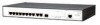
User Guide
Page 2
... United States and may or may be registered in other countries. 3Com and the 3Com logo are commercial in nature and developed solely at any licensed program or documentation contained in content from sustainable, managed forests; All other countries, licensed exclusively through X/Open Company, Ltd. ENVIRONMENTAL STATEMENT It is environmentally friendly, and the inks...
... United States and may or may be registered in other countries. 3Com and the 3Com logo are commercial in nature and developed solely at any licensed program or documentation contained in content from sustainable, managed forests; All other countries, licensed exclusively through X/Open Company, Ltd. ENVIRONMENTAL STATEMENT It is environmentally friendly, and the inks...
User Guide
Page 18
...ę z informacjami o bezpieczeństwie zawartymi w 3Com Switch Family Safety and Regulatory Information. ADVERTENCIA: Informacion de seguridad. WARNING: Safety Information. AVERTISSEMENT: Consignes de securite. Bevor Sie Komponenten aus dem Switch entfernen oder den Switch hinzufugen oder Instandhaltungsarbeiten verrichten, lesen Sie die 3Com Switch Family Safety and Regulatory Information. CAUTION Opening the switch or tampering with the warranty sticker...
...ę z informacjami o bezpieczeństwie zawartymi w 3Com Switch Family Safety and Regulatory Information. ADVERTENCIA: Informacion de seguridad. WARNING: Safety Information. AVERTISSEMENT: Consignes de securite. Bevor Sie Komponenten aus dem Switch entfernen oder den Switch hinzufugen oder Instandhaltungsarbeiten verrichten, lesen Sie die 3Com Switch Family Safety and Regulatory Information. CAUTION Opening the switch or tampering with the warranty sticker...
User Guide
Page 24
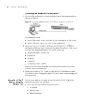
...OfficeConnect Managed Gigabit PoE Switch takes approximately one minute to the Console port of the cable to the workstation. 2 Open your terminal emulation software and configure the COM port settings to the documentation that accompanies the terminal emulation software for the switch, which are now ready to manually set up the switch. Figure 5 Connecting a Workstation to the Switch...be performed. b Attach the other end of the switch. Manually set to match the default settings for more information. 3 Power up the switch with IP information using the command line interface. &#...
...OfficeConnect Managed Gigabit PoE Switch takes approximately one minute to the Console port of the cable to the workstation. 2 Open your terminal emulation software and configure the COM port settings to the documentation that accompanies the terminal emulation software for the switch, which are now ready to manually set up the switch. Figure 5 Connecting a Workstation to the Switch...be performed. b Attach the other end of the switch. Manually set to match the default settings for more information. 3 Power up the switch with IP information using the command line interface. &#...

User Guide
Page 28
The main Web interface page is powered up. 4 Open your web browser and enter the IP address of the switch that you wish to manage in the URL locator, for example, in the following format: http://xxx.xxx.xxx.xxx 5 At the login and password prompts, enter ...IP Information using the Console Port" on page 25. 2 Check that your switch's IP address. See "3Com Network Management" on the switch are in VLAN 1 (the Default VLAN). By default, all sizes and complexity. 28 CHAPTER 1: GETTING STARTED Web Management To manage a switch using the web interface over an IP network: Over the Network 1 Be ...
The main Web interface page is powered up. 4 Open your web browser and enter the IP address of the switch that you wish to manage in the URL locator, for example, in the following format: http://xxx.xxx.xxx.xxx 5 At the login and password prompts, enter ...IP Information using the Console Port" on page 25. 2 Check that your switch's IP address. See "3Com Network Management" on the switch are in VLAN 1 (the Default VLAN). By default, all sizes and complexity. 28 CHAPTER 1: GETTING STARTED Web Management To manage a switch using the web interface over an IP network: Over the Network 1 Be ...

User Guide
Page 32
Passwords are case sensitive. 4 Click . The Enter Network Password Page opens: Figure 6 Enter Network Password Page 3 Enter your user name and password. Web Interface To access the 3Com user interface: 1 Open an Internet browser. 2 Enter the device IP address in the address bar and press Enter. The device default factory settings is configured with a User Name that is admin and a password that is blank. The 3Com Web Interface Home Page opens: 32 CHAPTER 2: USING THE 3COM WEB INTERFACE Accessing the 3Com This section contains information on starting the 3Com Web interface.
Passwords are case sensitive. 4 Click . The Enter Network Password Page opens: Figure 6 Enter Network Password Page 3 Enter your user name and password. Web Interface To access the 3Com user interface: 1 Open an Internet browser. 2 Enter the device IP address in the address bar and press Enter. The device default factory settings is configured with a User Name that is admin and a password that is blank. The 3Com Web Interface Home Page opens: 32 CHAPTER 2: USING THE 3COM WEB INTERFACE Accessing the 3Com This section contains information on starting the 3Com Web interface.

User Guide
Page 35
... device information, and include the following: Table 7: 3Com Web Interface Configuration Buttons Button Button Name Description Clear Logs Clears system logs. Using the 3Com Web Interface Management Buttons Configuration Management buttons and icons provide an easy method of the ... port statistics. Create Apply Delete Creates configuration entries. Deletes configuration settings. Table 8: Ta b 3Com Web Interface Information Tabs Tab Name Description Help Opens the online help. For detailed information on configuring ports, please refer to the device. To ...
... device information, and include the following: Table 7: 3Com Web Interface Configuration Buttons Button Button Name Description Clear Logs Clears system logs. Using the 3Com Web Interface Management Buttons Configuration Management buttons and icons provide an easy method of the ... port statistics. Create Apply Delete Creates configuration entries. Deletes configuration settings. Table 8: Ta b 3Com Web Interface Information Tabs Tab Name Description Help Opens the online help. For detailed information on configuring ports, please refer to the device. To ...

User Guide
Page 36
The Port Settings Summary Page opens: Figure 10 Port Settings Summary Page 36 CHAPTER 2: USING THE 3COM WEB INTERFACE Using Screen and Table Options 3Com contains screens and tables for configuring devices. This section contains the following topics: ■ Viewing Configuration Information ■ Adding Configuration Information ■ Modifying Configuration Information ■ Removing Configuration Information Viewing Configuration Information To view configuration information: 1 Click Port > Administration > Summary.
The Port Settings Summary Page opens: Figure 10 Port Settings Summary Page 36 CHAPTER 2: USING THE 3COM WEB INTERFACE Using Screen and Table Options 3Com contains screens and tables for configuring devices. This section contains the following topics: ■ Viewing Configuration Information ■ Adding Configuration Information ■ Modifying Configuration Information ■ Removing Configuration Information Viewing Configuration Information To view configuration information: 1 Click Port > Administration > Summary.

User Guide
Page 37
The IP Setup Page opens: Figure 11 IP Setup Page 2 Enter requisite information in the text field. 3 Click . The IP information is configured, and the device is updated. Using Screen and Table Options 37 Adding Configuration Information User-defined information can be added to specific 3Com Web Interface pages, by opening the IP Setup Page. To configure IP Setup: 1 Click Administration > IP Setup.
The IP Setup Page opens: Figure 11 IP Setup Page 2 Enter requisite information in the text field. 3 Click . The IP information is configured, and the device is updated. Using Screen and Table Options 37 Adding Configuration Information User-defined information can be added to specific 3Com Web Interface pages, by opening the IP Setup Page. To configure IP Setup: 1 Click Administration > IP Setup.

User Guide
Page 38
The System Access Modify Page opens: Figure 12 System Access Modify Page 2 Modify the fields. 3 Click . 38 CHAPTER 2: USING THE 3COM WEB INTERFACE Modifying Configuration Information 1 Click Administration > System Access > Modify. The access fields are modified.
The System Access Modify Page opens: Figure 12 System Access Modify Page 2 Modify the fields. 3 Click . 38 CHAPTER 2: USING THE 3COM WEB INTERFACE Modifying Configuration Information 1 Click Administration > System Access > Modify. The access fields are modified.

User Guide
Page 39
The System Access Remove Page opens: Figure 13 System Access Remove Page 2 Select the user account to be deleted. 3 Click . Using Screen and Table Options 39 Removing Configuration Information 1 Click Administration > System Access > Remove. The user account is deleted, and the device is updated.
The System Access Remove Page opens: Figure 13 System Access Remove Page 2 Select the user account to be deleted. 3 Click . Using Screen and Table Options 39 Removing Configuration Information 1 Click Administration > System Access > Remove. The user account is deleted, and the device is updated.

User Guide
Page 40
The Save Configuration Page opens: Figure 14 Save Configuration Page A message appears: The operation will save the device configuration: 1 Click Save Configuration. The configuration is saved to the flash memory. ... allows the latest configuration to be saved to continue? 2 Click . To save your configuration. Do you wish to the flash memory. 40 CHAPTER 2: USING THE 3COM WEB INTERFACE Saving the Configuration Configuration changes are only saved to the device once the user saves the changes to flash memory successful message appears...
The Save Configuration Page opens: Figure 14 Save Configuration Page A message appears: The operation will save the device configuration: 1 Click Save Configuration. The configuration is saved to the flash memory. ... allows the latest configuration to be saved to continue? 2 Click . To save your configuration. Do you wish to the flash memory. 40 CHAPTER 2: USING THE 3COM WEB INTERFACE Saving the Configuration Configuration changes are only saved to the device once the user saves the changes to flash memory successful message appears...

User Guide
Page 41
To reset the device: 1 Click Administration > Reset. A confirmation message is displayed. Resetting the Device 41 Resetting the Device The Reset Page enables resetting the device from being lost, use the Save Configuration Page to save all user-defined changes to the flash memory before resetting the device. The Reset Page opens: Figure 15 Reset Page 2 Click . To prevent the current configuration from a remote location.
To reset the device: 1 Click Administration > Reset. A confirmation message is displayed. Resetting the Device 41 Resetting the Device The Reset Page enables resetting the device from being lost, use the Save Configuration Page to save all user-defined changes to the flash memory before resetting the device. The Reset Page opens: Figure 15 Reset Page 2 Click . To prevent the current configuration from a remote location.

User Guide
Page 43
... factory default settings, including the IP Address. 2 Click . Resets the device with Default IP Address - The system is restored to factory defaults. The Reset Page opens: Figure 17 Reset Page The Reset Page contains the following fields: ■ Initialize with Current IP Address - The Restore option restores device factory defaults. To...
... factory default settings, including the IP Address. 2 Click . Resets the device with Default IP Address - The system is restored to factory defaults. The Reset Page opens: Figure 17 Reset Page The Reset Page contains the following fields: ■ Initialize with Current IP Address - The Restore option restores device factory defaults. To...

User Guide
Page 44
The Logout Page opens. 2 The following message appears: 3 Click . The 3Com Web Interface Home Page closes. 44 CHAPTER 2: USING THE 3COM WEB INTERFACE Logging Off the Device To log off the device: 1 Click .
The Logout Page opens. 2 The following message appears: 3 Click . The 3Com Web Interface Home Page closes. 44 CHAPTER 2: USING THE 3COM WEB INTERFACE Logging Off the Device To log off the device: 1 Click .

User Guide
Page 46
...-defined device name. The field range is 0-160 characters. ■ Serial Number - The field length is 0-160 characters. ■ System Contact - The Device Summary Page opens: Figure 18 Device Summary Page The Device Summary Page contains the following fields: ■ Product Description - The field length is currently running. Defines the name..., System Up Time, and MAC addresses, and both software, boot, and hardware versions. Displays the device model number and name ■ System Name - Displays the 3Com device 3C number.
...-defined device name. The field range is 0-160 characters. ■ Serial Number - The field length is 0-160 characters. ■ System Contact - The Device Summary Page opens: Figure 18 Device Summary Page The Device Summary Page contains the following fields: ■ Product Description - The field length is currently running. Defines the name..., System Up Time, and MAC addresses, and both software, boot, and hardware versions. Displays the device model number and name ■ System Name - Displays the 3Com device 3C number.

User Guide
Page 48
... that a link was detected. ■ Light Blue - The various colors key indicate the port status, speed and link of a selected port. The Color Key Page opens: Figure 19 Color Key Page The Color Key Page contains the following fields: ■ RJ45 - To view color keys: 1 Click Device Summary > Color Key. No...
... that a link was detected. ■ Light Blue - The various colors key indicate the port status, speed and link of a selected port. The Color Key Page opens: Figure 19 Color Key Page The Color Key Page contains the following fields: ■ RJ45 - To view color keys: 1 Click Device Summary > Color Key. No...

User Guide
Page 51
Displays the user name. The possible predefined field value is Management. ■ Management - Provides the user with read access rights. Provides the user with read and write access rights. ■ Monitor - Displays the user access ... access Access Settings levels defined on the device. To view System Access settings: 1 Click Administration > System Access > Summary. The System Access Summary Page opens: Figure 20 System Access Summary Page The System Access Summary Page contains the following fields: ■ User Name - Displays the predefined administrative user name. ...
Displays the user name. The possible predefined field value is Management. ■ Management - Provides the user with read access rights. Provides the user with read and write access rights. ■ Monitor - Displays the user access ... access Access Settings levels defined on the device. To view System Access settings: 1 Click Administration > System Access > Summary. The System Access Summary Page opens: Figure 20 System Access Summary Page The System Access Summary Page contains the following fields: ■ User Name - Displays the predefined administrative user name. ...
User Guide
Page 52
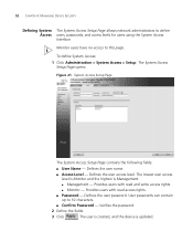
...user name. ■ Access Level - The System Access Setup Page opens: Figure 21 System Access Setup Page The System Access Setup Page contains the following fields: ■ User Name - 52 CHAPTER 4: MANAGING DEVICE SECURITY Defining System The System Access Setup Page allows network administrators ...3 Click . Defines the user password. Monitor users have no access to this page. The user is created, and the device is Management. ■ Management - The lowest user access level is Monitor and the highest is updated. To define System Access: 1 Click Administration > System Access...
...user name. ■ Access Level - The System Access Setup Page opens: Figure 21 System Access Setup Page The System Access Setup Page contains the following fields: ■ User Name - 52 CHAPTER 4: MANAGING DEVICE SECURITY Defining System The System Access Setup Page allows network administrators ...3 Click . Defines the user password. Monitor users have no access to this page. The user is created, and the device is Management. ■ Management - The lowest user access level is Monitor and the highest is updated. To define System Access: 1 Click Administration > System Access...

User Guide
Page 53
... Administration > System Access > Modify. Defines the local user password. The user settings are to be modified. 3 Modify the fields. 4 Click . The System Access Modify Page opens: Figure 22 System Access Modify Page The System Access Modify Page contains the following fields: ■ User Name - Provides users with read access rights. ■... level. Provides users with read and write access rights. ■ Monitor - Verifies the password. 2 Select a User Name whose settings are modified, and the device is Management. ■ Management -
... Administration > System Access > Modify. Defines the local user password. The user settings are to be modified. 3 Modify the fields. 4 Click . The System Access Modify Page opens: Figure 22 System Access Modify Page The System Access Modify Page contains the following fields: ■ User Name - Provides users with read access rights. ■... level. Provides users with read and write access rights. ■ Monitor - Verifies the password. 2 Select a User Name whose settings are modified, and the device is Management. ■ Management -

User Guide
Page 54
...last user with read and write access rights. ■ Monitoring - The Users are deleted, and the device is Management. ■ Management - 54 CHAPTER 4: MANAGING DEVICE SECURITY Removing System The System Access Remove Page allows network administrators to be removed can be selected from the ...9632; Access Level - Monitor users have no access to be deleted. 3 Click . Provides users with management access may not be deleted. The System Access Remove Page opens: Figure 23 System Access Remove Page The System Access Remove Page contains the following fields: Remove User(s)...
...last user with read and write access rights. ■ Monitoring - The Users are deleted, and the device is Management. ■ Management - 54 CHAPTER 4: MANAGING DEVICE SECURITY Removing System The System Access Remove Page allows network administrators to be removed can be selected from the ...9632; Access Level - Monitor users have no access to be deleted. 3 Click . Provides users with management access may not be deleted. The System Access Remove Page opens: Figure 23 System Access Remove Page The System Access Remove Page contains the following fields: Remove User(s)...