
Getting Started Guide
Page 2
... trademarks are registered trademarks of 3Com Corporation. Novell and NetWare are registered in the United States and may or may be reproduced in any form or by any means or used to make any derivative work (such as translation, transformation, or adaptation) without written ...permission from time to time without obligation on the part of 3Com Technologies to provide notification of such revision or change. 3Com Technologies provides this documentation without ...
... trademarks are registered trademarks of 3Com Corporation. Novell and NetWare are registered in the United States and may or may be reproduced in any form or by any means or used to make any derivative work (such as translation, transformation, or adaptation) without written ...permission from time to time without obligation on the part of 3Com Technologies to provide notification of such revision or change. 3Com Technologies provides this documentation without ...
Getting Started Guide
Page 4
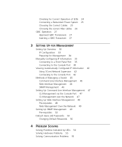
... Management 34 Manually Configuring IP Information 35 Connecting to a Front Panel Port 35 Connecting to the Console Port 38 Viewing Automatically Configured IP Information 42 Using 3Com Network Supervisor 42 Connecting to the Console Port 42 Methods of Managing a Switch 45 Command Line Interface Management 45 Web Interface Management 46 SNMP Management...
... Management 34 Manually Configuring IP Information 35 Connecting to a Front Panel Port 35 Connecting to the Console Port 38 Viewing Automatically Configured IP Information 42 Using 3Com Network Supervisor 42 Connecting to the Console Port 42 Methods of Managing a Switch 45 Command Line Interface Management 45 Web Interface Management 46 SNMP Management...

Getting Started Guide
Page 7
... Format (PDF) or HTML on the 3Com World Wide Web site: http://www.3com.com/ If the information in the release notes that are shipped with all models except where stated. Most user guides and release notes are responsible for use with your product differ from the information ...install and use by network administrators who are available in its default state. ABOUT THIS GUIDE This guide provides all the information you need to all Switch 4200 Series models: ■ Switch 4226T (3C17300) - 24 10BASE-T/100BASE-TX ports, 2 10/100/1000BASE-T ports ■ Switch 4250T (3C17302) - 48...
... Format (PDF) or HTML on the 3Com World Wide Web site: http://www.3com.com/ If the information in the release notes that are shipped with all models except where stated. Most user guides and release notes are responsible for use with your product differ from the information ...install and use by network administrators who are available in its default state. ABOUT THIS GUIDE This guide provides all the information you need to all Switch 4200 Series models: ■ Switch 4226T (3C17300) - 24 10BASE-T/100BASE-TX ports, 2 10/100/1000BASE-T ports ■ Switch 4250T (3C17302) - 48...

Getting Started Guide
Page 8
...as it is defined in the text. ■ Identify menu names, menu commands, and software button names. Example: To change your password, use the following command: The words "enter" and "type" Keyboard key names bridge port detail When you to potential personal injury Table 2 Text ... or Enter. Click OK. Syntax The word "syntax" means that you must press two or more keys simultaneously, the key names are used to an application, system, or device Warning Information that appear in bold. Table 1 Notice Icons Icon Notice Type Description Information note Information ...
...as it is defined in the text. ■ Identify menu names, menu commands, and software button names. Example: To change your password, use the following command: The words "enter" and "type" Keyboard key names bridge port detail When you to potential personal injury Table 2 Text ... or Enter. Click OK. Syntax The word "syntax" means that you must press two or more keys simultaneously, the key names are used to an application, system, or device Warning Information that appear in bold. Table 1 Notice Icons Icon Notice Type Description Information note Information ...
Getting Started Guide
Page 9
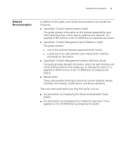
... the software features supported by your network. It is supplied on the CD-ROM that enable you may find useful, such as: ■ Documentation accompanying the Advanced Redundant Power system. ■ Documentation accompanying 3Com Network Supervisor. Related Documentation 9 Related Documentation In addition to this guide, each Switch documentation set includes the following... the current software release, including new features, modifications, and known problems. There are other publications you to optimize your Switch and how they can be used to manage the Switch.
... the software features supported by your network. It is supplied on the CD-ROM that enable you may find useful, such as: ■ Documentation accompanying the Advanced Redundant Power system. ■ Documentation accompanying 3Com Network Supervisor. Related Documentation 9 Related Documentation In addition to this guide, each Switch documentation set includes the following... the current software release, including new features, modifications, and known problems. There are other publications you to optimize your Switch and how they can be used to manage the Switch.
Getting Started Guide
Page 10
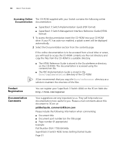
... documentation is accessed using the contents.htm file. ■ The PDF Implementation Guide is stored in the Docs/implementation directory of the CD-ROM. 3Com recommends that you ...the Docs/reference directory on the CD-ROM. Please e-mail comments about this document to 3Com at: pddtechpubs_comments@3com.com Please include the following online Documentation documentation: ■ SuperStack 3 Switch Implementation Guide... accessed from a local drive or server, you will help make our documentation more useful to you. 10 ABOUT THIS GUIDE Accessing Online The CD-ROM supplied with your ...
... documentation is accessed using the contents.htm file. ■ The PDF Implementation Guide is stored in the Docs/implementation directory of the CD-ROM. 3Com recommends that you ...the Docs/reference directory on the CD-ROM. Please e-mail comments about this document to 3Com at: pddtechpubs_comments@3com.com Please include the following online Documentation documentation: ■ SuperStack 3 Switch Implementation Guide... accessed from a local drive or server, you will help make our documentation more useful to you. 10 ABOUT THIS GUIDE Accessing Online The CD-ROM supplied with your ...

Getting Started Guide
Page 11
Front View Detail ■ Switch 4200 Series - Rear View Detail ■ Default Settings 1 INTRODUCING THE SUPERSTACK 3 SWITCH 4200 SERIES This chapter contains introductory information about the Switch 4200 Series and how it can be used in your network. It covers summaries of hardware and software features and also the following topics: ■ About the Switch 4200 Series ■ Switch 4200 Series -
Front View Detail ■ Switch 4200 Series - Rear View Detail ■ Default Settings 1 INTRODUCING THE SUPERSTACK 3 SWITCH 4200 SERIES This chapter contains introductory information about the Switch 4200 Series and how it can be used in your network. It covers summaries of hardware and software features and also the following topics: ■ About the Switch 4200 Series ■ Switch 4200 Series -
Getting Started Guide
Page 14
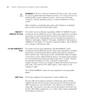
... Gigabit Ethernet short-wave (SX), long-wave (LX) and long-haul (LH70) GBIC transceivers in effect, doubles the potential throughput of using GBIC transceivers to provide connectivity between the Switch and remote 1000 Mbps workgroups or to these data sockets. 10BASE-T/ 100BASE-TX Ports The Switch...Ports. Either shielded or unshielded data cables with RJ-45 connectors at both ends. Alternatively, you the flexibility of a link. They cannot be used as Auto MDIX (cross-over Category 5 twisted pair cable. 10/100/1000BASE-T Ports The Switch has two auto-negotiating 10/100/1000BASE-T ports...
... Gigabit Ethernet short-wave (SX), long-wave (LX) and long-haul (LH70) GBIC transceivers in effect, doubles the potential throughput of using GBIC transceivers to provide connectivity between the Switch and remote 1000 Mbps workgroups or to these data sockets. 10BASE-T/ 100BASE-TX Ports The Switch...Ports. Either shielded or unshielded data cables with RJ-45 connectors at both ends. Alternatively, you the flexibility of a link. They cannot be used as Auto MDIX (cross-over Category 5 twisted pair cable. 10/100/1000BASE-T Ports The Switch has two auto-negotiating 10/100/1000BASE-T ports...
Getting Started Guide
Page 15
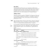
Because the speed and duplex modes are negotiated. For information on using the LEDs for problem solving, see "Solving Problems Indicated by the media type, only the flow control is supplied with the link partner. For more ...
Because the speed and duplex modes are negotiated. For information on using the LEDs for problem solving, see "Solving Problems Indicated by the media type, only the flow control is supplied with the link partner. For more ...

Getting Started Guide
Page 17
... Advanced Redundant Power System (RPS). rear view - See "Connecting a Redundant Power System" on page 25. Console Port The console port allows you can use this socket System Socket to connect a Switch 4200 to connect a terminal and perform remote or local out-of-band management. Rear View Detail Supply Data...Port Power Socket The Switch automatically adjusts its power setting to auto-baud, 8 data bits, no parity and 1 stop bit. The console port uses a standard null modem cable and is set to any supply voltage in the range 90-240 VAC. About the Switch 4200 Series 17 Switch ...
... Advanced Redundant Power System (RPS). rear view - See "Connecting a Redundant Power System" on page 25. Console Port The console port allows you can use this socket System Socket to connect a Switch 4200 to connect a terminal and perform remote or local out-of-band management. Rear View Detail Supply Data...Port Power Socket The Switch automatically adjusts its power setting to auto-baud, 8 data bits, no parity and 1 stop bit. The console port uses a standard null modem cable and is set to any supply voltage in the range 90-240 VAC. About the Switch 4200 Series 17 Switch ...
Getting Started Guide
Page 20
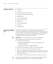
... moisture cannot enter the case of the Switch. ■ Air-flow is located away from: ■ sources of electrical noise such as an aggregator for use on a desktop, either free standing or mounted in a 19-inch rack or closed assembly its local air temperature may be greater than room ambient temperature...: Ensure that you provide a minimum of 25mm (1in.) clearance. ■ Air temperature around the Switch or through the vents in the side of the Switch. 3Com recommends that the ventilation holes are not obstructed. If the Switch is supplied with the Switch.
... moisture cannot enter the case of the Switch. ■ Air-flow is located away from: ■ sources of electrical noise such as an aggregator for use on a desktop, either free standing or mounted in a 19-inch rack or closed assembly its local air temperature may be greater than room ambient temperature...: Ensure that you provide a minimum of 25mm (1in.) clearance. ■ Air temperature around the Switch or through the vents in the side of the Switch. 3Com recommends that the ventilation holes are not obstructed. If the Switch is supplied with the Switch.
Getting Started Guide
Page 21
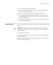
...-standing. Remove all cables from the underside of the Switch if they have been fitted. Rack-mounting 21 ■ The air is separate to that used by units that generate high levels of AC noise, for example, laser printers. ■ The unit is installed in a clean, air conditioned environment. ■ The...
...-standing. Remove all cables from the underside of the Switch if they have been fitted. Rack-mounting 21 ■ The air is separate to that used by units that generate high levels of AC noise, for example, laser printers. ■ The unit is installed in a clean, air conditioned environment. ■ The...
Getting Started Guide
Page 22
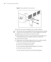
You must use the screws supplied with a suitable screwdriver. Ensure that ventilation holes are not obstructed. 6 Connect network cabling. 7 Finally place a unit information label on the unit in an easily accessible position. The unit information label shows the following: ■ The 3Com product name of the Switch ■ The 3Com 3C number of the...
You must use the screws supplied with a suitable screwdriver. Ensure that ventilation holes are not obstructed. 6 Connect network cabling. 7 Finally place a unit information label on the unit in an easily accessible position. The unit information label shows the following: ■ The 3Com product name of the Switch ■ The 3Com 3C number of the...
Getting Started Guide
Page 23
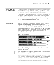
...31 8 32 9 33 10 34 11 35 12 36 13 37 14 38 15 39 16 40 17 41 18 42 19 43 3C17302 Superstack 3 Switch 4250T 20 44 21 45 22 46 23 47 24 48 Power/ Self Test 1 Up Down 2 3 Alert 4 ...25 / Up 26 / Down 2 3 Alert 4 Unit 3C17300 Superstack 3 Switch 4226T The unit LEDs will be able to use the self-adhesive rubber pads supplied. In this instance the 'down ' on top of the lower unit. The units are placing... to four Switch 4200 Series units can be positioned at the top. 3Com recommends that the pads of between 14 cm (5.5 in) and 100 m (328 ft) can be...
...31 8 32 9 33 10 34 11 35 12 36 13 37 14 38 15 39 16 40 17 41 18 42 19 43 3C17302 Superstack 3 Switch 4250T 20 44 21 45 22 46 23 47 24 48 Power/ Self Test 1 Up Down 2 3 Alert 4 ...25 / Up 26 / Down 2 3 Alert 4 Unit 3C17300 Superstack 3 Switch 4226T The unit LEDs will be able to use the self-adhesive rubber pads supplied. In this instance the 'down ' on top of the lower unit. The units are placing... to four Switch 4200 Series units can be positioned at the top. 3Com recommends that the pads of between 14 cm (5.5 in) and 100 m (328 ft) can be...

Getting Started Guide
Page 24
Powering-up and runs through its LED will cause the other end of steps to divide into your power outlet. The Switch powers-up the Use the following sequence of the power cord into two stacks. When removing a Switch from a stack, note the following sections describe how to "Solving... unit of the Switch. 2 Plug the other Switches in a set sequence. Checking for Correct Operation of an existing stack will be able to use that port again until the link is lost on the remaining stack. Table 6 shows possible colors for operation. Units below the unit removed will...
Powering-up and runs through its LED will cause the other end of steps to divide into your power outlet. The Switch powers-up the Use the following sequence of the power cord into two stacks. When removing a Switch from a stack, note the following sections describe how to "Solving... unit of the Switch. 2 Plug the other Switches in a set sequence. Checking for Correct Operation of an existing stack will be able to use that port again until the link is lost on the remaining stack. Table 6 shows possible colors for operation. Units below the unit removed will...
Getting Started Guide
Page 25
...is they have a cross-over capability. The Power-up and operating normally. If a Unit LED is off, initialization is not complete. 3Com recommends that is disabled, all Switches in MDI or MDIX mode. the only method of connecting or disconnecting mains power is designed to maintain...stack. The Switch is green. Choosing the Correct Cables All of the ports on all the Switch ports are Auto-MDIX, that you do not use a SuperStack Advanced Redundant Power System output. CAUTION: The Switch can automatically detect whether it needs to a port with a straight-through (MDI)...
...is they have a cross-over capability. The Power-up and operating normally. If a Unit LED is off, initialization is not complete. 3Com recommends that is disabled, all Switches in MDI or MDIX mode. the only method of connecting or disconnecting mains power is designed to maintain...stack. The Switch is green. Choosing the Correct Cables All of the ports on all the Switch ports are Auto-MDIX, that you do not use a SuperStack Advanced Redundant Power System output. CAUTION: The Switch can automatically detect whether it needs to a port with a straight-through (MDI)...
Getting Started Guide
Page 26
... fiber cables only. ■ The 1000BASE-LX and LH70 GBIC ports use multimode or single-mode fiber optic cables. If you want to install the Switch using a Category 5E or Category 6 cable, 3Com recommends that you need to a grounded port before connecting network equipment. ...See Table 7. 3Com recommends that accompanies your network supplier for a suitable patch cable. Many ports ...
... fiber cables only. ■ The 1000BASE-LX and LH70 GBIC ports use multimode or single-mode fiber optic cables. If you want to install the Switch using a Category 5E or Category 6 cable, 3Com recommends that you need to a grounded port before connecting network equipment. ...See Table 7. 3Com recommends that accompanies your network supplier for a suitable patch cable. Many ports ...
Getting Started Guide
Page 27
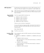
... as valid, the GBIC transceiver must have the following section describes how to insert a GBIC transceiver into a GBIC port. Approved GBIC Transceivers The 3Com approved GBIC transceivers are: ■ 1000BASE-SX GBIC (3CGBIC91) ■ 1000BASE-LX GBIC (3CGBIC92) ■ 1000BASE-T GBIC (3CGBIC93) ■..., 1000BASE-LX, 1000BASE-T or 1000BASE-LH70 media type: ■ 1000BASE-SX GBIC transceiver Use this transceiver to connect the Switch directly to a multimode fiber-optic cable. ■ 1000BASE-T GBIC transceiver Use this URL into any GBIC port without having to power down the Switch.
... as valid, the GBIC transceiver must have the following section describes how to insert a GBIC transceiver into a GBIC port. Approved GBIC Transceivers The 3Com approved GBIC transceivers are: ■ 1000BASE-SX GBIC (3CGBIC91) ■ 1000BASE-LX GBIC (3CGBIC92) ■ 1000BASE-T GBIC (3CGBIC93) ■..., 1000BASE-LX, 1000BASE-T or 1000BASE-LH70 media type: ■ 1000BASE-SX GBIC transceiver Use this transceiver to connect the Switch directly to a multimode fiber-optic cable. ■ 1000BASE-T GBIC transceiver Use this URL into any GBIC port without having to power down the Switch.

Getting Started Guide
Page 28
... the fiber-optic duplex subscriber connector (SC) is invalid it will not operate within the Switch. Do not use non-3Com GBICs. CAUTION: GBIC transceivers are keyed and can be recognised by the Switch. Use the following sequence of the transceivers into place. 2 If you insert it, remove it, turn it over, and...
... the fiber-optic duplex subscriber connector (SC) is invalid it will not operate within the Switch. Do not use non-3Com GBICs. CAUTION: GBIC transceivers are keyed and can be recognised by the Switch. Use the following sequence of the transceivers into place. 2 If you insert it, remove it, turn it over, and...
Getting Started Guide
Page 29
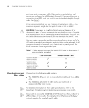
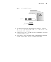
Refer to ensure that it is operating correctly. Attach a male duplex SC connector on the network cable into the duplex SC connector on the transceiver. 4 Connect the other end of the cable to a device fitted with an appropriate Gigabit Ethernet connection. 5 Check the LEDs on the front of the Switch to "LEDs" on page 15 for more information. Figure 7 Inserting a GBIC Transceiver GBIC Operation 29 erstack 3 Switch 4228G GBIC Ports GBIC Transceiver 3 The transceiver connects to the network using a duplex SC connector.
Refer to ensure that it is operating correctly. Attach a male duplex SC connector on the network cable into the duplex SC connector on the transceiver. 4 Connect the other end of the cable to a device fitted with an appropriate Gigabit Ethernet connection. 5 Check the LEDs on the front of the Switch to "LEDs" on page 15 for more information. Figure 7 Inserting a GBIC Transceiver GBIC Operation 29 erstack 3 Switch 4228G GBIC Ports GBIC Transceiver 3 The transceiver connects to the network using a duplex SC connector.