
Getting Started Guide
Page 9
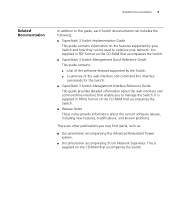
... accompanying the Advanced Redundant Power system. ■ Documentation accompanying 3Com Network Supervisor. Related Documentation 9 Related Documentation In addition to this guide, each Switch documentation set includes the following: ■ SuperStack 3 Switch Implementation Guide This guide contains information on the CD-ROM that accompanies the Switch. It is supplied on the features supported by...
... accompanying the Advanced Redundant Power system. ■ Documentation accompanying 3Com Network Supervisor. Related Documentation 9 Related Documentation In addition to this guide, each Switch documentation set includes the following: ■ SuperStack 3 Switch Implementation Guide This guide contains information on the CD-ROM that accompanies the Switch. It is supplied on the features supported by...
Getting Started Guide
Page 16
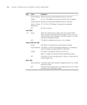
Yellow flashing Packets are being transmitted/received on the port. Unit LEDs 1-4 Green When the Switch forms a stack with the Power Supply Unit. Refer to flash. Alert LED Green flashing The Switch Alert LED has been configured via the CLI or Web Interface to be off (... the stack and that a link is enabled. Green / Yellow A 10, 100 or 1000 Mbps link present but disabled. Off The Switch initialization process is powered-up and operating normally. Yellow A 10 or 100 Mbps link is present and the port is present. 16 CHAPTER 1: INTRODUCING THE SUPERSTACK 3 SWITCH 4200 SERIES...
Yellow flashing Packets are being transmitted/received on the port. Unit LEDs 1-4 Green When the Switch forms a stack with the Power Supply Unit. Refer to flash. Alert LED Green flashing The Switch Alert LED has been configured via the CLI or Web Interface to be off (... the stack and that a link is enabled. Green / Yellow A 10, 100 or 1000 Mbps link present but disabled. Off The Switch initialization process is powered-up and operating normally. Yellow A 10 or 100 Mbps link is present and the port is present. 16 CHAPTER 1: INTRODUCING THE SUPERSTACK 3 SWITCH 4200 SERIES...

Getting Started Guide
Page 17
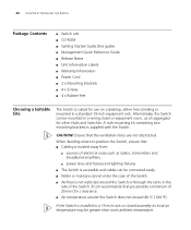
... 17 Switch 4200 Series Figure 4 Switch 4200 Series - Redundant Power To protect against internal power supply failure, you to a SuperStack Advanced Redundant Power System (RPS). See "Connecting a Redundant Power System" on page 25. The console port uses a standard null modem cable and is set to any supply voltage in the range 90-240 VAC. rear view...
... 17 Switch 4200 Series Figure 4 Switch 4200 Series - Redundant Power To protect against internal power supply failure, you to a SuperStack Advanced Redundant Power System (RPS). See "Connecting a Redundant Power System" on page 25. The console port uses a standard null modem cable and is set to any supply voltage in the range 90-240 VAC. rear view...
Getting Started Guide
Page 20
...Switch is accessible and cables can be mounted in the side of the Switch. 3Com recommends that you provide a minimum of the Switch. ■ Air-flow ... installed in a standard 19-inch equipment rack. A rack-mounting kit containing two mounting brackets is supplied with the Switch. 20 CHAPTER 2: INSTALLING THE SWITCH Package Contents ■ Switch unit ■ ... Quick Reference Guide ■ Release Notes ■ Unit Information Labels ■ Warranty Information ■ Power Cord ■ 2 x Mounting brackets ■ 4 x Screws ■ 4 x Rubber feet Choosing a Suitable Site The...
...Switch is accessible and cables can be mounted in the side of the Switch. 3Com recommends that you provide a minimum of the Switch. ■ Air-flow ... installed in a standard 19-inch equipment rack. A rack-mounting kit containing two mounting brackets is supplied with the Switch. 20 CHAPTER 2: INSTALLING THE SWITCH Package Contents ■ Switch unit ■ ... Quick Reference Guide ■ Release Notes ■ Unit Information Labels ■ Warranty Information ■ Power Cord ■ 2 x Mounting brackets ■ 4 x Screws ■ 4 x Rubber feet Choosing a Suitable Site The...
Getting Started Guide
Page 23
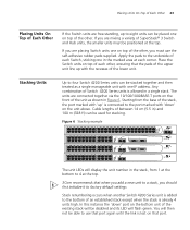
...35 12 36 13 37 14 38 15 39 16 40 17 41 18 42 19 43 3C17302 Superstack 3 Switch 4250T 20 44 21 45 22 46 23 47 24 48 Power/ Self Test 1 Up Down 2 3 Alert 4 Unit 49 50 1 13 2 14 ... of Each Other If the Switch units are free-standing, up to use the self-adhesive rubber pads supplied. You will display the unit number in a single stack. In this instance the 'down ' on... its LED will be placed one in Figure 6. Starting from 1 at the bottom to 4 at the top. 3Com recommends that when you add a new unit to a stack, you must be stacked together and then treated as ...
...35 12 36 13 37 14 38 15 39 16 40 17 41 18 42 19 43 3C17302 Superstack 3 Switch 4250T 20 44 21 45 22 46 23 47 24 48 Power/ Self Test 1 Up Down 2 3 Alert 4 Unit 49 50 1 13 2 14 ... of Each Other If the Switch units are free-standing, up to use the self-adhesive rubber pads supplied. You will display the unit number in a single stack. In this instance the 'down ' on... its LED will be placed one in Figure 6. Starting from 1 at the bottom to 4 at the top. 3Com recommends that when you add a new unit to a stack, you must be stacked together and then treated as ...
Getting Started Guide
Page 25
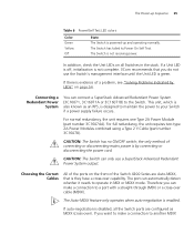
...can make a connection to operate in the stack. Therefore you want to make a connection to your Switch if a power supply failure occurs. The Switch has failed its Power On Self Test. If there is also known as MDIX (cross-over cable (MDIX). This unit, which is evidence... normally. If a Unit LED is off, initialization is not complete. 3Com recommends that is designed to maintain the power to a port with a straight-through (MDI) or a cross-over ). Connecting a Redundant Power System You can automatically detect whether it needs to another MDIX The Switch...
...can make a connection to operate in the stack. Therefore you want to make a connection to your Switch if a power supply failure occurs. The Switch has failed its Power On Self Test. If there is also known as MDIX (cross-over cable (MDIX). This unit, which is evidence... normally. If a Unit LED is off, initialization is not complete. 3Com recommends that is designed to maintain the power to a port with a straight-through (MDI) or a cross-over ). Connecting a Redundant Power System You can automatically detect whether it needs to another MDIX The Switch...

Getting Started Guide
Page 42
Refer to the documentation that accompanies your Switch to the network. 2 Power-up the Switch and wait for two minutes. 3 Launch 3Com Network Supervisor and run the Auto-discovery wizard. 3Com Network Supervisor will auto-discover the new Switch and display the IP information that has... local connection to the console port, rather than a remote one via the console port directly, or through a modem. ■ Documentation supplied with terminal emulation software installed, such as the Switch, because Auto-IP addresses are non-routable. Connecting to the Console Port Alternatively, you ...
Refer to the documentation that accompanies your Switch to the network. 2 Power-up the Switch and wait for two minutes. 3 Launch 3Com Network Supervisor and run the Auto-discovery wizard. 3Com Network Supervisor will auto-discover the new Switch and display the IP information that has... local connection to the console port, rather than a remote one via the console port directly, or through a modem. ■ Documentation supplied with terminal emulation software installed, such as the Switch, because Auto-IP addresses are non-routable. Connecting to the Console Port Alternatively, you ...

Getting Started Guide
Page 54
... the same at both ends. Auto-negotiation problems will flash green/yellow alternately to the 'problem' device then contact your supplier for advice. The Power LED does not light Check that : ■ The Switch and the device at the other end of the link (or cable) are connected... cable is satisfactory ■ Auto-negotiation settings are being used (cross-over or straight). Firstly, check the power cord by LEDs If the LEDs on the Switch indicate a problem, refer to the supply outlet. 54 CHAPTER 4: PROBLEM SOLVING Solving Problems Indicated by : ■ testing it 's LED will occur ...
... the same at both ends. Auto-negotiation problems will flash green/yellow alternately to the 'problem' device then contact your supplier for advice. The Power LED does not light Check that : ■ The Switch and the device at the other end of the link (or cable) are connected... cable is satisfactory ■ Auto-negotiation settings are being used (cross-over or straight). Firstly, check the power cord by LEDs If the LEDs on the Switch indicate a problem, refer to the supply outlet. 54 CHAPTER 4: PROBLEM SOLVING Solving Problems Indicated by : ■ testing it 's LED will occur ...

Getting Started Guide
Page 55
... to obtain a registered IP address. IP addresses have a unique IP address. See "Approved GBIC Transceivers"on your network management application (such as 3Com Network Supervisor). Solving Hardware Problems 55 Solving Hardware Problems SNMP fan fail trap hardware failure In the rare event of IP addressing, and how to... requirements for example a Switch or Hub) must have the format n.n.n.n where n is 192.168.100.8. To do this, remove and reconnect all power supplies. 4 If a further fan fail trap is faulty To correct this problem, completely remove the GBIC and replace it .
... to obtain a registered IP address. IP addresses have a unique IP address. See "Approved GBIC Transceivers"on your network management application (such as 3Com Network Supervisor). Solving Hardware Problems 55 Solving Hardware Problems SNMP fan fail trap hardware failure In the rare event of IP addressing, and how to... requirements for example a Switch or Hub) must have the format n.n.n.n where n is 192.168.100.8. To do this, remove and reconnect all power supplies. 4 If a further fan fail trap is faulty To correct this problem, completely remove the GBIC and replace it .

Getting Started Guide
Page 56
...address as long as it is enabled, do not have been set aside specially for this example is 255.255.255.0. If your network. 3Com suggests you are part of a group of IP addresses that Spanning Tree is enabled. InterNIC Registration Services is the organization responsible for a ... connection to your network will not operate correctly. The following : 1 Power off all units in the stack. 2 Check all units in the series 192.160.100.X (where X is , you access the Internet, you must apply for supplying registered IP addresses. If you use addresses in the stack. if you ...
...address as long as it is enabled, do not have been set aside specially for this example is 255.255.255.0. If your network. 3Com suggests you are part of a group of IP addresses that Spanning Tree is enabled. InterNIC Registration Services is the organization responsible for a ... connection to your network will not operate correctly. The following : 1 Power off all units in the stack. 2 Check all units in the series 192.160.100.X (where X is , you access the Internet, you must apply for supplying registered IP addresses. If you use addresses in the stack. if you ...

Getting Started Guide
Page 60
WARNING: Power Cord Set: This must be of type H03VVF3GO.75 (minimum). ■ The supply plug must comply with section 107-2-D1, standard DK2-1a or DK2-5a. ■ The supply plug must comply with an EN60320/IEC320 appliance inlet. and Canada United Kingdom only Europe only: Denmark Switzerland ■...Important Safety Information WARNING: Installation and removal of the unit must be installed below the narrower units. WARNING: Connect the unit to an earthed power supply to the unit and not the wall plug) must have a configuration for the country where it is : No. 18 AWG Type SV or...
WARNING: Power Cord Set: This must be of type H03VVF3GO.75 (minimum). ■ The supply plug must comply with section 107-2-D1, standard DK2-1a or DK2-5a. ■ The supply plug must comply with an EN60320/IEC320 appliance inlet. and Canada United Kingdom only Europe only: Denmark Switzerland ■...Important Safety Information WARNING: Installation and removal of the unit must be installed below the narrower units. WARNING: Connect the unit to an earthed power supply to the unit and not the wall plug) must have a configuration for the country where it is : No. 18 AWG Type SV or...

Getting Started Guide
Page 61
... must be connected to these sockets. WARNING: RJ-45 Ports. They cannot be powered from IT† supplies. Important Safety Information 61 WARNING: The socket outlet must be powered by disconnecting the power cord from the outlet. Only connect RJ-45 data connectors, network telephony systems, or... network telephones to IEC 950. If your supplies are of the Switch 4200 Series, only use a modem ...
... must be connected to these sockets. WARNING: RJ-45 Ports. They cannot be powered from IT† supplies. Important Safety Information 61 WARNING: The socket outlet must be powered by disconnecting the power cord from the outlet. Only connect RJ-45 data connectors, network telephony systems, or... network telephones to IEC 950. If your supplies are of the Switch 4200 Series, only use a modem ...

Getting Started Guide
Page 71
... SPECIFICATIONS Switch 4226T (3C17300) Physical Dimensions Environmental Requirements Operating Temperature Storage Temperature Operating Humidity Standards Safety Agency Certifications EMC Emissions Immunity Heat Dissipation Power Supply AC Line Frequency Input Voltage Current Rating (continued) Height: 44 mm (1.7 in.) x Width: 440 mm (17.3 in.) x ... °F) -40 ° to +70 °C (-40 ° to 158 °F) 10-95% relative humidity, non-condensing EN60068 to 3Com schedule (Package testing: paras 2.1, 2.2, 2.30, and 2.32. UL 60950, EN60950, CSA 22.2 No. 60950, IEC 60950 CISPRR 22 Class ...
... SPECIFICATIONS Switch 4226T (3C17300) Physical Dimensions Environmental Requirements Operating Temperature Storage Temperature Operating Humidity Standards Safety Agency Certifications EMC Emissions Immunity Heat Dissipation Power Supply AC Line Frequency Input Voltage Current Rating (continued) Height: 44 mm (1.7 in.) x Width: 440 mm (17.3 in.) x ... °F) -40 ° to +70 °C (-40 ° to 158 °F) 10-95% relative humidity, non-condensing EN60068 to 3Com schedule (Package testing: paras 2.1, 2.2, 2.30, and 2.32. UL 60950, EN60950, CSA 22.2 No. 60950, IEC 60950 CISPRR 22 Class ...
Getting Started Guide
Page 73
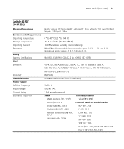
Switch 4250T (3C17302) 73 Switch 4250T (3C17302) Physical Dimensions Environmental Requirements Operating Temperature Storage Temperature Operating Humidity Standards Safety Agency Certifications EMC Emissions Immunity Heat Dissipation Power Supply AC Line Frequency Input Voltage Current Rating Standards Supported Height: 44 mm (1.7 in...°F) -40 ° to +70 °C (-40 ° to 158 °F) 10-95% relative humidity, non-condensing EN60068 to 3Com schedule (Package testing: paras 2.1, 2.2, 2.30, and 2.32. Operational testing: paras 2.1, 2.2, 2.30 and 2.13). UL60950, EN60950, CSA ...
Switch 4250T (3C17302) 73 Switch 4250T (3C17302) Physical Dimensions Environmental Requirements Operating Temperature Storage Temperature Operating Humidity Standards Safety Agency Certifications EMC Emissions Immunity Heat Dissipation Power Supply AC Line Frequency Input Voltage Current Rating Standards Supported Height: 44 mm (1.7 in...°F) -40 ° to +70 °C (-40 ° to 158 °F) 10-95% relative humidity, non-condensing EN60068 to 3Com schedule (Package testing: paras 2.1, 2.2, 2.30, and 2.32. Operational testing: paras 2.1, 2.2, 2.30 and 2.13). UL60950, EN60950, CSA ...
Getting Started Guide
Page 74
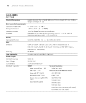
...Switch 4228G (3C17304) Physical Dimensions Environmental Requirements Operating Temperature Storage Temperature Operating Humidity Standards Safety Agency Certifications EMC Emissions Immunity Heat Dissipation Power Supply AC Line Frequency Input Voltage Current Rating Standards Supported Height: 44 mm (1.7 in.) x Width: 440 mm (17.3 in.)...104 °F) -40 ° to +70 °C (-40 ° to 158 °F) 10-95% relative humidity, non-condensing EN60068 to 3Com schedule (Package testing: paras 2.1, 2.2, 2.30, and 2.32. UL60950, EN60950, CSA 22.2 No. 60950, IEC 60950 CISPR 22 Class A, EN55022 ...
...Switch 4228G (3C17304) Physical Dimensions Environmental Requirements Operating Temperature Storage Temperature Operating Humidity Standards Safety Agency Certifications EMC Emissions Immunity Heat Dissipation Power Supply AC Line Frequency Input Voltage Current Rating Standards Supported Height: 44 mm (1.7 in.) x Width: 440 mm (17.3 in.)...104 °F) -40 ° to +70 °C (-40 ° to 158 °F) 10-95% relative humidity, non-condensing EN60068 to 3Com schedule (Package testing: paras 2.1, 2.2, 2.30, and 2.32. UL60950, EN60950, CSA 22.2 No. 60950, IEC 60950 CISPR 22 Class A, EN55022 ...
