
Owners Manual
Page 6
...the headlight bulb ...7-28 Replacing the tail/brake light bulb ...7-30 TABLE OF CONTENTS LOCATION OF IMPORTANT LABELS ...1-1 SAFETY INFORMATION ...2-1 DESCRIPTION ...3-1 Left view ...3-1 Right view ...3-2 Controls and instruments...3-3 INSTRUMENT AND CONTROL FUNCTIONS ...4-1 Main switch/steering lock ...4-1 Indicator lights and warning lights ...4-2 Multi-function meter unit ...4-3 Handlebar switches ...4-6 Clutch lever ...4-7 Shift pedal ...4-8 Brake lever ...4-8 Brake pedal ...4-8 Fuel tank cap ...4-9 Fuel ...4-9 Fuel tank breather/overflow hose ...4-11 Catalytic converter ...4-11 Rider seat...
...the headlight bulb ...7-28 Replacing the tail/brake light bulb ...7-30 TABLE OF CONTENTS LOCATION OF IMPORTANT LABELS ...1-1 SAFETY INFORMATION ...2-1 DESCRIPTION ...3-1 Left view ...3-1 Right view ...3-2 Controls and instruments...3-3 INSTRUMENT AND CONTROL FUNCTIONS ...4-1 Main switch/steering lock ...4-1 Indicator lights and warning lights ...4-2 Multi-function meter unit ...4-3 Handlebar switches ...4-6 Clutch lever ...4-7 Shift pedal ...4-8 Brake lever ...4-8 Brake pedal ...4-8 Fuel tank cap ...4-9 Fuel ...4-9 Fuel tank breather/overflow hose ...4-11 Catalytic converter ...4-11 Rider seat...
Owners Manual
Page 7
... LIMITED WARRANTY ...10-7 YAMAHA EXTENDED SERVICE (Y.E.S.) ...10-9 TABLE OF CONTENTS Replacing a front turn signal light bulb ...7-30 Replacing a rear turn signal light bulb ...7-31 Replacing a license plate light bulb ...7-32 Supporting the motorcycle ...7-33 Troubleshooting ...7-33 Troubleshooting chart ...7-35 MOTORCYCLE CARE AND STORAGE ...8-1 Matte color caution ...8-1 Care ...8-1 Storage ...8-3 SPECIFICATIONS ...9-1 CONSUMER INFORMATION...10-1 Identification numbers ...10-1 Reporting safety defects ...10-3 Motorcycle noise regulation ...10-4 Maintenance record ...10-5 YAMAHA MOTOR...
... LIMITED WARRANTY ...10-7 YAMAHA EXTENDED SERVICE (Y.E.S.) ...10-9 TABLE OF CONTENTS Replacing a front turn signal light bulb ...7-30 Replacing a rear turn signal light bulb ...7-31 Replacing a license plate light bulb ...7-32 Supporting the motorcycle ...7-33 Troubleshooting ...7-33 Troubleshooting chart ...7-35 MOTORCYCLE CARE AND STORAGE ...8-1 Matte color caution ...8-1 Care ...8-1 Storage ...8-3 SPECIFICATIONS ...9-1 CONSUMER INFORMATION...10-1 Identification numbers ...10-1 Reporting safety defects ...10-3 Motorcycle noise regulation ...10-4 Maintenance record ...10-5 YAMAHA MOTOR...
Owners Manual
Page 14
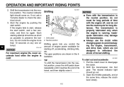
... and handling if the weight distribution of the operator, passenger, accessories and cargo must not exceed the maximum load limit. Use extra care when riding a motorcycle that these aftermarket companies produce. Here, along with no connection to the handlebar, front fork, or front fender. Genuine Yamaha Accessories Choosing accessories for your load (suspension-adjustable models only), and check the condition and pressure of...
... and handling if the weight distribution of the operator, passenger, accessories and cargo must not exceed the maximum load limit. Use extra care when riding a motorcycle that these aftermarket companies produce. Here, along with no connection to the handlebar, front fork, or front fender. Genuine Yamaha Accessories Choosing accessories for your load (suspension-adjustable models only), and check the condition and pressure of...
Owners Manual
Page 15
... of lights or engine power. G 2 Aftermarket Tires and Rims The tires and rims that change any way reduce ground clearance or cornering clearance, limit suspension travel, steering travel or control operation, or obscure lights or reflectors. • Accessories fitted to the handlebar or the front fork area can create instability due to improper weight distribution or aerodynamic changes. Installing aftermarket products or having other modifications performed to your vehicle that...
... of lights or engine power. G 2 Aftermarket Tires and Rims The tires and rims that change any way reduce ground clearance or cornering clearance, limit suspension travel, steering travel or control operation, or obscure lights or reflectors. • Accessories fitted to the handlebar or the front fork area can create instability due to improper weight distribution or aerodynamic changes. Installing aftermarket products or having other modifications performed to your vehicle that...
Owners Manual
Page 21
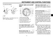
.... Neutral indicator light " " Fuel level warning light " " Engine trouble warning light " Oil level warning light " " Turn signal indicator light " High beam indicator light " " " " Oil level warning light " " This warning light comes on if the engine oil level is turned to "ON", or if the warning light remains on, have a Yamaha dealer check the electrical circuit. INSTRUMENT AND CONTROL FUNCTIONS To unlock the steering EAU49391 EAU11080 Indicator lights and warning lights High beam indicator light " " This indicator light comes on when the high beam of the warning light...
.... Neutral indicator light " " Fuel level warning light " " Engine trouble warning light " Oil level warning light " " Turn signal indicator light " High beam indicator light " " " " Oil level warning light " " This warning light comes on if the engine oil level is turned to "ON", or if the warning light remains on, have a Yamaha dealer check the electrical circuit. INSTRUMENT AND CONTROL FUNCTIONS To unlock the steering EAU49391 EAU11080 Indicator lights and warning lights High beam indicator light " " This indicator light comes on when the high beam of the warning light...

Owners Manual
Page 24
... a Yamaha dealer check the vehicle. Push the "SELECT" and "RESET" switches together for at least one second. This model is detected in order to avoid engine damage. 1 1 1. Brightness level display This function allows you do not reset the fuel reserve tripmeter manually, it by pushing the "SELECT" switch, and then push the "RESET" switch for various electrical circuits. INSTRUMENT AND CONTROL FUNCTIONS...
... a Yamaha dealer check the vehicle. Push the "SELECT" and "RESET" switches together for at least one second. This model is detected in order to avoid engine damage. 1 1 1. Brightness level display This function allows you do not reset the fuel reserve tripmeter manually, it by pushing the "SELECT" switch, and then push the "RESET" switch for various electrical circuits. INSTRUMENT AND CONTROL FUNCTIONS...
Owners Manual
Page 25
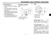
..." switch after the vehicle 4-6 Turn the key to the center position. The odometer/tripmeter/clock display will self-cancel after five seconds. 4. Horn switch " " 1. 2. 3. 4. EAU12430 Turn signal switch " / " To signal a right-hand turn , push this switch to " " for the high beam and to " ". Engine stop switch " "SELECT" switch "RESET" switch Start switch " " / " 4 EAU12400 Dimmer switch " / " Set this switch to " " for the low beam. INSTRUMENT AND CONTROL FUNCTIONS To set the brightness 1. When released, the switch...
..." switch after the vehicle 4-6 Turn the key to the center position. The odometer/tripmeter/clock display will self-cancel after five seconds. 4. Horn switch " " 1. 2. 3. 4. EAU12430 Turn signal switch " / " To signal a right-hand turn , push this switch to " " for the high beam and to " ". Engine stop switch " "SELECT" switch "RESET" switch Start switch " " / " 4 EAU12400 Dimmer switch " / " Set this switch to " " for the low beam. INSTRUMENT AND CONTROL FUNCTIONS To set the brightness 1. When released, the switch...
Owners Manual
Page 26
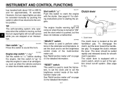
... the center position. However, the turn signal lights will come on when the key is turned to "ON" and the start switch is equipped with the starter. EAU42535 "RESET" switch This switch is located at an intersection. See "Multi-function meter unit" on page 4-3 for detailed information. 4-7 The clutch lever is used to perform selections in after it has returned to sound the horn...
... the center position. However, the turn signal lights will come on when the key is turned to "ON" and the start switch is equipped with the starter. EAU42535 "RESET" switch This switch is located at an intersection. See "Multi-function meter unit" on page 4-3 for detailed information. 4-7 The clutch lever is used to perform selections in after it has returned to sound the horn...

Owners Manual
Page 33
... holding the vehicle upright. Do not subject the shock absorber assembly to open flame or other high heat source. Do not deform or damage the cylinder in poor damping performance. Therefore, check 3. Take the shock absorber assembly to excessive gas pressure. EWA10221 WARNING This shock absorber assembly contains highly pressurized nitrogen gas. Read and understand the following information before starting off system.) EWA10241 4 WARNING The vehicle must not...
... holding the vehicle upright. Do not subject the shock absorber assembly to open flame or other high heat source. Do not deform or damage the cylinder in poor damping performance. Therefore, check 3. Take the shock absorber assembly to excessive gas pressure. EWA10221 WARNING This shock absorber assembly contains highly pressurized nitrogen gas. Read and understand the following information before starting off system.) EWA10241 4 WARNING The vehicle must not...
Owners Manual
Page 39
... for the corresponding warning light circuit check. 6-1 G an engine auto-stop the engine in case of a turnover. EWA10271 WARNING Failure to familiarize yourself with : G a lean angle sensor to restart the engine. G Oil level warning light G Fuel level warning light G Engine trouble warning light ECA15484 6 NOTICE If a warning light does not come on initially when the key is a control or function you do so will prevent the engine from starting , one of control, which could...
... for the corresponding warning light circuit check. 6-1 G an engine auto-stop the engine in case of a turnover. EWA10271 WARNING Failure to familiarize yourself with : G a lean angle sensor to restart the engine. G Oil level warning light G Fuel level warning light G Engine trouble warning light ECA15484 6 NOTICE If a warning light does not come on initially when the key is a control or function you do so will prevent the engine from starting , one of control, which could...
Owners Manual
Page 40
... running. Shift the transmission into the neutral position. ECA11042 EAU16671 ECA10260 Shifting 5 4 3 2 N NOTICE G 2 1 1 1. Inadequate lubrication may damage the transmission. Shift pedal 2. The transmission is properly lubricated only when the engine is cold! Shifting gears lets you control the amount of time with the transmission in the illustration. Always use the clutch while changing gears to avoid damaging the engine, transmission, and drive train, which are shown in the neutral position, do not tow...
... running. Shift the transmission into the neutral position. ECA11042 EAU16671 ECA10260 Shifting 5 4 3 2 N NOTICE G 2 1 1 1. Inadequate lubrication may damage the transmission. Shift pedal 2. The transmission is properly lubricated only when the engine is cold! Shifting gears lets you control the amount of time with the transmission in the illustration. Always use the clutch while changing gears to avoid damaging the engine, transmission, and drive train, which are shown in the neutral position, do not tow...
Owners Manual
Page 43
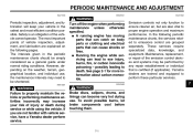
... emission control devices and systems may be performed by any repair establishment or individual that can catch on body parts or clothing and electrical parts that is an obligation of the vehicle owner/operator. G A running engine has moving parts that can cause shocks or fires. G Running the engine while servicing can become very hot during service or while using the vehicle. The most efficient condition possible. WARNING Brake discs...
... emission control devices and systems may be performed by any repair establishment or individual that can catch on body parts or clothing and electrical parts that is an obligation of the vehicle owner/operator. G A running engine has moving parts that can cause shocks or fires. G Running the engine while servicing can become very hot during service or while using the vehicle. The most efficient condition possible. WARNING Brake discs...
Owners Manual
Page 69
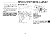
... the fuse box, which contains the fuses for clock) Headlight fuse Spare fuse 1 1. 2. 3. 4. 2 3 4 Fuse box Main fuse Fuel injection system fuse Fuel injection system spare fuse TIP To access the fuel injection system fuse, remove the starter relay cover by pulling it upward. 7 7-27 Ignition fuse Taillight fuse Signaling system fuse Backup fuse (for the individual circuits, are located under the rider seat. (See page 4-12.) 1 6 2 3 4 5 4. PERIODIC MAINTENANCE AND ADJUSTMENT is turned to the battery...
... the fuse box, which contains the fuses for clock) Headlight fuse Spare fuse 1 1. 2. 3. 4. 2 3 4 Fuse box Main fuse Fuel injection system fuse Fuel injection system spare fuse TIP To access the fuel injection system fuse, remove the starter relay cover by pulling it upward. 7 7-27 Ignition fuse Taillight fuse Signaling system fuse Backup fuse (for the individual circuits, are located under the rider seat. (See page 4-12.) 1 6 2 3 4 5 4. PERIODIC MAINTENANCE AND ADJUSTMENT is turned to the battery...
Owners Manual
Page 70
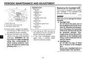
Fuel injection system spare fuse 3. Do not use a fuse of the bulb, and the bulb life will be adversely affected. Turn the key to the electrical system and possibly a fire. [EWA15131] Specified fuses: Main fuse: 40.0 A Headlight fuse: 20.0 A Taillight fuse: 10.0 A Signaling system fuse: 10.0 A Ignition fuse: 15.0 A Fuel injection system fuse: 10.0 A Backup fuse: 10.0 A Replacing the headlight bulb This model is blown, replace it as follows. PERIODIC MAINTENANCE AND ADJUSTMENT EAU48511 1 2 3 1. Turn the key to check if...
Fuel injection system spare fuse 3. Do not use a fuse of the bulb, and the bulb life will be adversely affected. Turn the key to the electrical system and possibly a fire. [EWA15131] Specified fuses: Main fuse: 40.0 A Headlight fuse: 20.0 A Taillight fuse: 10.0 A Signaling system fuse: 10.0 A Ignition fuse: 15.0 A Fuel injection system fuse: 10.0 A Backup fuse: 10.0 A Replacing the headlight bulb This model is blown, replace it as follows. PERIODIC MAINTENANCE AND ADJUSTMENT EAU48511 1 2 3 1. Turn the key to check if...
Owners Manual
Page 81
... the battery, see page 7-26. 8-4 TIP Make any necessary repairs before storing the motorcycle. 8 Remove the spark plug caps from deteriorating. 3. Fill up the fuel tank and add fuel stabilizer (if available) to ground the spark plug electrodes while turning the engine over several times with oil.) WARNING! from becoming degraded in an excessively cold or warm place [less than 30 °C (90°F)]. Lubricate all control cables...
... the battery, see page 7-26. 8-4 TIP Make any necessary repairs before storing the motorcycle. 8 Remove the spark plug caps from deteriorating. 3. Fill up the fuel tank and add fuel stabilizer (if available) to ground the spark plug electrodes while turning the engine over several times with oil.) WARNING! from becoming degraded in an excessively cold or warm place [less than 30 °C (90°F)]. Lubricate all control cables...
Owners Manual
Page 82
... US gal, 0.75 Imp.gal) Fuel injection: Throttle body: ID mark: XVS95A 5S71 00 XVS95AC 5S72 10 Spark plug(s): Manufacturer/model: NGK/CPR7EA-9 Spark plug gap: 0.8-0.9 mm (0.031-0.035 in) Clutch: Clutch type: Wet, multiple-disc Weight: Curb weight: 278 kg (613 lb) Transmission: Primary reduction ratio: 72/43 (1.674) Final drive: Belt Secondary reduction ratio: 70/30 (2.333) Transmission type: Constant mesh 5-speed Operation: Left foot operation...
... US gal, 0.75 Imp.gal) Fuel injection: Throttle body: ID mark: XVS95A 5S71 00 XVS95AC 5S72 10 Spark plug(s): Manufacturer/model: NGK/CPR7EA-9 Spark plug gap: 0.8-0.9 mm (0.031-0.035 in) Clutch: Clutch type: Wet, multiple-disc Weight: Curb weight: 278 kg (613 lb) Transmission: Primary reduction ratio: 72/43 (1.674) Final drive: Belt Secondary reduction ratio: 70/30 (2.333) Transmission type: Constant mesh 5-speed Operation: Left foot operation...
Owners Manual
Page 84
SPECIFICATIONS Tail/brake light: 12 V, 5.0 W/21.0 W × 1 Front turn signal/position light: 12 V, 21 W/5.0 W × 2 Rear turn signal light: 12 V, 21.0 W × 2 License plate light: 12 V, 3.8 W × 2 Meter lighting: LED Neutral indicator light: LED High beam indicator light: LED Oil level warning light: LED Turn signal indicator light: LED Fuel level warning light: LED Engine trouble warning light: LED Fuel injection system fuse: 10.0 A Backup fuse: 10.0 A Fuses: Main fuse: 40.0 A Headlight fuse: 20.0 A Taillight fuse: 10.0 A Signaling system fuse: 10.0 A Ignition fuse: 15.0 A 9 ...
SPECIFICATIONS Tail/brake light: 12 V, 5.0 W/21.0 W × 1 Front turn signal/position light: 12 V, 21 W/5.0 W × 2 Rear turn signal light: 12 V, 21.0 W × 2 License plate light: 12 V, 3.8 W × 2 Meter lighting: LED Neutral indicator light: LED High beam indicator light: LED Oil level warning light: LED Turn signal indicator light: LED Fuel level warning light: LED Engine trouble warning light: LED Fuel injection system fuse: 10.0 A Backup fuse: 10.0 A Fuses: Main fuse: 40.0 A Headlight fuse: 20.0 A Taillight fuse: 10.0 A Signaling system fuse: 10.0 A Ignition fuse: 15.0 A 9 ...
Owners Manual
Page 91
... maintenance, are not covered by this inspection and registration must take place within ten (10) days after transfer. SPECIFIC EXCLUSIONS from defects in material or workmanship, which would cause it is imperative that new Yamaha motorcycles will be charged for non-Yamaha-authorized renting, leasing or other than those used in warranty repairs will , free of charge, repair or replace...
... maintenance, are not covered by this inspection and registration must take place within ten (10) days after transfer. SPECIFIC EXCLUSIONS from defects in material or workmanship, which would cause it is imperative that new Yamaha motorcycles will be charged for non-Yamaha-authorized renting, leasing or other than those used in warranty repairs will , free of charge, repair or replace...
Owners Manual
Page 92
... DEPARTMENT P.O. No. Each Yamaha motorcycle dealer is expected to your satisfaction at the time of having the dealer do not operate or maintain my new motorcycle exactly as it to second owners? If a question or problem arises regarding the warranty, first contact the owner of normal maintenance services, non-warranty repairs, accident and collision damages, and oil, oil filters, air filters, spark plugs, and brake shoes. The customer...
... DEPARTMENT P.O. No. Each Yamaha motorcycle dealer is expected to your satisfaction at the time of having the dealer do not operate or maintain my new motorcycle exactly as it to second owners? If a question or problem arises regarding the warranty, first contact the owner of normal maintenance services, non-warranty repairs, accident and collision damages, and oil, oil filters, air filters, spark plugs, and brake shoes. The customer...
Owners Manual
Page 95
...18 Brake light switches...7-18 Brake pedal ...4-8 Fuel tank breather/overflow hose...4-11 Fuel tank cap...4-9 Fuses, replacing...7-27 Part locations ...3-1 R Rear suspension, lubricating ...7-24 RESET switch...4-7 Rider seat ...4-12 H Handlebar switches ...4-6 Headlight bulb, replacing...7-28 Helmet holder...4-12 High beam indicator light...4-2 Horn switch ...4-7 S Safety defects, reporting...10-3 Safety information...2-1 SELECT switch...4-7 Shifting...6-2 Shift pedal...4-8 Shock absorber assembly, adjusting ...4-13 Sidestand...4-14 Sidestand, checking and lubricating ...7-23 Spark plugs...
...18 Brake light switches...7-18 Brake pedal ...4-8 Fuel tank breather/overflow hose...4-11 Fuel tank cap...4-9 Fuses, replacing...7-27 Part locations ...3-1 R Rear suspension, lubricating ...7-24 RESET switch...4-7 Rider seat ...4-12 H Handlebar switches ...4-6 Headlight bulb, replacing...7-28 Helmet holder...4-12 High beam indicator light...4-2 Horn switch ...4-7 S Safety defects, reporting...10-3 Safety information...2-1 SELECT switch...4-7 Shifting...6-2 Shift pedal...4-8 Shock absorber assembly, adjusting ...4-13 Sidestand...4-14 Sidestand, checking and lubricating ...7-23 Spark plugs...