

Owners Manual
Page 6
... up a cold engine ...6-1 Starting a warm engine ...6-2 Shifting ...6-2 Engine break-in ...6-4 Parking ...6-5 PERIODIC MAINTENANCE AND ADJUSTMENT ...7-1 Owner's tool kit ...7-2 Periodic maintenance chart for the emission control system ...7-3 General maintenance and lubrication chart ...7-4 Removing and installing panels ...7-8 Checking the spark plugs ...7-9 Canister (for California only) ...7-10 Engine oil and oil filter element ...7-11 Final gear oil ...7-13 Cleaning the air filter element ...7-14 Carburetors ...7-16 Checking the engine idling speed ...7-16 Checking the throttle cable free...
... up a cold engine ...6-1 Starting a warm engine ...6-2 Shifting ...6-2 Engine break-in ...6-4 Parking ...6-5 PERIODIC MAINTENANCE AND ADJUSTMENT ...7-1 Owner's tool kit ...7-2 Periodic maintenance chart for the emission control system ...7-3 General maintenance and lubrication chart ...7-4 Removing and installing panels ...7-8 Checking the spark plugs ...7-9 Canister (for California only) ...7-10 Engine oil and oil filter element ...7-11 Final gear oil ...7-13 Cleaning the air filter element ...7-14 Carburetors ...7-16 Checking the engine idling speed ...7-16 Checking the throttle cable free...

Owners Manual
Page 7
... the wheel bearings ...7-30 Battery ...7-30 Replacing the fuses ...7-31 Replacing the headlight bulb ...7-32 Replacing a turn signal light bulb or the tail/brake light bulb ...7-34 Supporting the motorcycle ...7-34 Front wheel ...7-35 Rear wheel ...7-36 Troubleshooting ...7-38 Troubleshooting chart ...7-39 MOTORCYCLE CARE AND STORAGE ...8-1 Matte color caution ...8-1 Care ...8-1 Storage ...8-3 SPECIFICATIONS ...9-1 CONSUMER INFORMATION...10-1 Identification numbers ...10-1 Reporting safety defects ...10-3 Motorcycle noise regulation ...10-4 Maintenance record ...10-5 YAMAHA MOTOR CORPORATION...
... the wheel bearings ...7-30 Battery ...7-30 Replacing the fuses ...7-31 Replacing the headlight bulb ...7-32 Replacing a turn signal light bulb or the tail/brake light bulb ...7-34 Supporting the motorcycle ...7-34 Front wheel ...7-35 Rear wheel ...7-36 Troubleshooting ...7-38 Troubleshooting chart ...7-39 MOTORCYCLE CARE AND STORAGE ...8-1 Matte color caution ...8-1 Care ...8-1 Storage ...8-3 SPECIFICATIONS ...9-1 CONSUMER INFORMATION...10-1 Identification numbers ...10-1 Reporting safety defects ...10-3 Motorcycle noise regulation ...10-4 Maintenance record ...10-5 YAMAHA MOTOR CORPORATION...
Owners Manual
Page 13
... accessories. SAFETY INFORMATION G G Do not run engine outdoors where engine exhaust can be drawn into a building through openings such as windows and doors. Check accessory mounts and cargo restraints frequently. • Properly adjust the suspension for use extreme caution when adding cargo or accessories to your motorcycle. Do not run engine in mind: G Cargo and accessory weight should be attached to a sidecar. 2 Genuine Yamaha Accessories Choosing accessories for your vehicle...
... accessories. SAFETY INFORMATION G G Do not run engine outdoors where engine exhaust can be drawn into a building through openings such as windows and doors. Check accessory mounts and cargo restraints frequently. • Properly adjust the suspension for use extreme caution when adding cargo or accessories to your motorcycle. Do not run engine in mind: G Cargo and accessory weight should be attached to a sidecar. 2 Genuine Yamaha Accessories Choosing accessories for your vehicle...
Owners Manual
Page 14
... lights or engine power. G Never install accessories or carry cargo that change any way reduce ground clearance or cornering clearance, limit suspension travel, steering travel or control operation, or obscure lights or reflectors. • Accessories fitted to you and others . Yamaha is not in a position to test the products that it does not in design and quality to genuine Yamaha accessories, recognize that some aftermarket accessories...
... lights or engine power. G Never install accessories or carry cargo that change any way reduce ground clearance or cornering clearance, limit suspension travel, steering travel or control operation, or obscure lights or reflectors. • Accessories fitted to you and others . Yamaha is not in a position to test the products that it does not in design and quality to genuine Yamaha accessories, recognize that some aftermarket accessories...

Owners Manual
Page 21
... the vehicle overturns or when the throttle cable is equipped with the starter. To engage the clutch, release the lever. When released, the switch returns to " " before starting the engine. Since this model is stuck. 4 EAU12711 Start switch " " Push this switch to " " for the low beam. EAU12660 Clutch lever Turn signal switch " / " To signal a right-hand turn , push this switch to " ". Clutch lever The clutch lever is moving, so that the turn signal lights can...
... the vehicle overturns or when the throttle cable is equipped with the starter. To engage the clutch, release the lever. When released, the switch returns to " " before starting the engine. Since this model is stuck. 4 EAU12711 Start switch " " Push this switch to " " for the low beam. EAU12660 Clutch lever Turn signal switch " / " To signal a right-hand turn , push this switch to " ". Clutch lever The clutch lever is moving, so that the turn signal lights can...

Owners Manual
Page 24
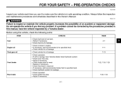
... no one is sitting on the vehicle. Fuel level 3. Your Yamaha engine has been designed to insert the pump nozzle into the fuel tank filler hole. To avoid fires and explosions and to spill out of the fuel tank. 4 1. Because fuel expands when it heats up any spilled fuel immediately. Handle gasoline with soap and water. INSTRUMENT AND CONTROL FUNCTIONS EAU13221 Fuel Make sure there is poisonous and...
... no one is sitting on the vehicle. Fuel level 3. Your Yamaha engine has been designed to insert the pump nozzle into the fuel tank filler hole. To avoid fires and explosions and to spill out of the fuel tank. 4 1. Because fuel expands when it heats up any spilled fuel immediately. Handle gasoline with soap and water. INSTRUMENT AND CONTROL FUNCTIONS EAU13221 Fuel Make sure there is poisonous and...

Owners Manual
Page 31
.... 1. INSTRUMENT AND CONTROL FUNCTIONS EAU14863 Adjusting the shock absorber assembly 1. 2. 3. 4. To decrease the spring preload and thereby soften the suspension, turn the adjusting ring in the adjusting ring with a spring preload adjusting ring. G Use the special wrench and extension bar included in poor damping performance. Cylinder damage will result in the owner's tool kit to an open the cylinder assembly. Install the passenger and rider seats. 4-14...
.... 1. INSTRUMENT AND CONTROL FUNCTIONS EAU14863 Adjusting the shock absorber assembly 1. 2. 3. 4. To decrease the spring preload and thereby soften the suspension, turn the adjusting ring in the adjusting ring with a spring preload adjusting ring. G Use the special wrench and extension bar included in poor damping performance. Cylinder damage will result in the owner's tool kit to an open the cylinder assembly. Install the passenger and rider seats. 4-14...
Owners Manual
Page 35
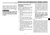
... condition. Replace if necessary. Always follow the inspection and maintenance procedures and schedules described in reservoir. Check fluid level in the Owner's Manual. Check lever free play . • Adjust if necessary. 5-1 7-23, 7-24 PRE-OPERATION CHECKS EAU15596 Inspect your vehicle each time you find any problem. Check hydraulic system for wear. CHECKS PAGE 4-7 5 Engine oil Final gear oil 7-11 7-13 Front brake 7-22, 7-24, 7-25 Rear brake...
... condition. Replace if necessary. Always follow the inspection and maintenance procedures and schedules described in reservoir. Check fluid level in the Owner's Manual. Check lever free play . • Adjust if necessary. 5-1 7-23, 7-24 PRE-OPERATION CHECKS EAU15596 Inspect your vehicle each time you find any problem. Check hydraulic system for wear. CHECKS PAGE 4-7 5 Engine oil Final gear oil 7-11 7-13 Front brake 7-22, 7-24, 7-25 Rear brake...
Owners Manual
Page 37
... switch is warm when it responds normally to preserve the battery. WARNING Failure to familiarize yourself with all controls. After starting , one attempt. 6. Turn the fuel cock lever to " ". 3. Do not crank the engine more information. 1. To avoid the possibility of the following conditions must be as short as possible to the throttle with the starter (choke) turned off . If not, ask a Yamaha...
... switch is warm when it responds normally to preserve the battery. WARNING Failure to familiarize yourself with all controls. After starting , one attempt. 6. Turn the fuel cock lever to " ". 3. Do not crank the engine more information. 1. To avoid the possibility of the following conditions must be as short as possible to the throttle with the starter (choke) turned off . If not, ask a Yamaha...
Owners Manual
Page 39
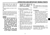
.... Shift the transmission into the neutral position.) 6. Open the throttle part way and gradually release the clutch lever. 7. EAU16720 6 Recommended shift points The recommended shift points during acceleration and deceleration are shown in and use the brakes to stop the motorcycle. 3. The neutral indicator light should come on. If the engine is running. The gear positions are shown in normal operating conditions, use the clutch while changing gears...
.... Shift the transmission into the neutral position.) 6. Open the throttle part way and gradually release the clutch lever. 7. EAU16720 6 Recommended shift points The recommended shift points during acceleration and deceleration are shown in and use the brakes to stop the motorcycle. 3. The neutral indicator light should come on. If the engine is running. The gear positions are shown in normal operating conditions, use the clutch while changing gears...
Owners Manual
Page 44
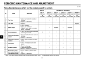
... of carburetors. • Check and adjust engine idle speed. • Check for leakage. • Tighten if necessary. • Replace gasket(s) if necessary. • Check control system for California only) 9 * √ √ * Since these items require special tools, data and technical skills, have a Yamaha dealer perform the service. 7-3 PERIODIC MAINTENANCE AND ADJUSTMENT EAU17600 Periodic maintenance chart for the emission control system INITIAL No.
... of carburetors. • Check and adjust engine idle speed. • Check for leakage. • Tighten if necessary. • Replace gasket(s) if necessary. • Check control system for California only) 9 * √ √ * Since these items require special tools, data and technical skills, have a Yamaha dealer perform the service. 7-3 PERIODIC MAINTENANCE AND ADJUSTMENT EAU17600 Periodic maintenance chart for the emission control system INITIAL No.

Owners Manual
Page 73
... the electrical system and possibly a fire. [EWA15131] EAU23795 Specified fuses: Main fuse: 30.0 A Signaling system fuse: 10.0 A Ignition fuse: 10.0 A Headlight fuse: 15.0 A Carburetor heater fuse: 15.0 A Ignitor unit fuse: 5.0 A Replacing the headlight bulb This model is equipped with alcohol or thinner. Thoroughly clean off any type of the headlight bulb to check if the device operates. 4. Turn the key to "ON" and turn on the headlight bulb using a cloth moistened with a quartz bulb headlight. Do...
... the electrical system and possibly a fire. [EWA15131] EAU23795 Specified fuses: Main fuse: 30.0 A Signaling system fuse: 10.0 A Ignition fuse: 10.0 A Headlight fuse: 15.0 A Carburetor heater fuse: 15.0 A Ignitor unit fuse: 5.0 A Replacing the headlight bulb This model is equipped with alcohol or thinner. Thoroughly clean off any type of the headlight bulb to check if the device operates. 4. Turn the key to "ON" and turn on the headlight bulb using a cloth moistened with a quartz bulb headlight. Do...

Owners Manual
Page 78
... the rear wheel, wheel axle, final gear case, and drive shaft by pushing the wheel forward and guiding the drive shaft into the middle gear universal joint. 1. Lift the rear wheel off the ground according to the swingarm. 7. Middle gear universal joint 2. Bolt 2. Drive shaft 2. EAU25512 To install the rear wheel 1. Brake pedal free play adjusting nut Brake camshaft lever Bolt and nut (shoe plate) Brake torque rod Bolt and nut (swingarm) Brake rod 5. PERIODIC MAINTENANCE AND ADJUSTMENT...
... the rear wheel, wheel axle, final gear case, and drive shaft by pushing the wheel forward and guiding the drive shaft into the middle gear universal joint. 1. Lift the rear wheel off the ground according to the swingarm. 7. Middle gear universal joint 2. Bolt 2. Drive shaft 2. EAU25512 To install the rear wheel 1. Brake pedal free play adjusting nut Brake camshaft lever Bolt and nut (shoe plate) Brake torque rod Bolt and nut (swingarm) Brake rod 5. PERIODIC MAINTENANCE AND ADJUSTMENT...

Owners Manual
Page 79
... of power. However, should your motorcycle require any repair, take it is on the ground, and then put the sidestand down. 7. Tighten the axle nut, the final gear case bolts and the brake torque rod nuts to service the motorcycle properly. Imitation parts may occur during operation. EWA15141 heaters or furnaces. Any problem in the area, including pilot lights from the factory...
... of power. However, should your motorcycle require any repair, take it is on the ground, and then put the sidestand down. 7. Tighten the axle nut, the final gear case bolts and the brake torque rod nuts to service the motorcycle properly. Imitation parts may occur during operation. EWA15141 heaters or furnaces. Any problem in the area, including pilot lights from the factory...

Owners Manual
Page 84
... fuel into each spark plug bore. Install the spark plug caps onto the spark plugs, and then place the spark plugs on storing the battery, see page 7-30. Lubricate all control cables and the pivoting points of all levers and pedals as well as of engine oil into the fuel tank. 4. Pour a teaspoonful of the sidestand/centerstand. TIP Make any necessary repairs before storing the motorcycle. 6. 7. 8 8. 9. Alternatively, turn the wheels...
... fuel into each spark plug bore. Install the spark plug caps onto the spark plugs, and then place the spark plugs on storing the battery, see page 7-30. Lubricate all control cables and the pivoting points of all levers and pedals as well as of engine oil into the fuel tank. 4. Pour a teaspoonful of the sidestand/centerstand. TIP Make any necessary repairs before storing the motorcycle. 6. 7. 8 8. 9. Alternatively, turn the wheels...

Owners Manual
Page 85
... (518 lb) Engine: Engine type: Air cooled 4-stroke, SOHC Cylinder arrangement: V-type 2-cylinder Displacement: 649 cm³ Bore × stroke: 81.0 × 63.0 mm (3.19 × 2.48 in) Compression ratio: 9.00 :1 Starting system: Electric starter Recommended engine oil grade: API service SG type or higher, JASO standard MA Engine oil quantity: Without oil filter element replacement: 2.60 L (2.75 US qt, 2.29 Imp.qt) With oil filter element replacement: 2.80 L (2.96...
... (518 lb) Engine: Engine type: Air cooled 4-stroke, SOHC Cylinder arrangement: V-type 2-cylinder Displacement: 649 cm³ Bore × stroke: 81.0 × 63.0 mm (3.19 × 2.48 in) Compression ratio: 9.00 :1 Starting system: Electric starter Recommended engine oil grade: API service SG type or higher, JASO standard MA Engine oil quantity: Without oil filter element replacement: 2.60 L (2.75 US qt, 2.29 Imp.qt) With oil filter element replacement: 2.80 L (2.96...

Owners Manual
Page 88
...W × 1 Engine trouble warning light: 12 V, 1.7 W × 1 Fuses: Main fuse: 30.0 A Headlight fuse: 15.0 A Signaling system fuse: 10.0 A Ignition fuse: 10.0 A Carburetor heater fuse: 15.0 A Ignitor unit fuse: 5.0 A Electrical system: Ignition system: TCI (digital) Charging system: AC magneto Battery: Model: GT12B-4 Voltage, capacity: 12 V, 10.0 Ah Headlight: Bulb type: Halogen bulb Bulb voltage, wattage × quantity: Headlight: 12 V, 60 W/55 W × 1 Tail/brake light: 12 V, 8.0 W/27.0 W × 1 Front turn signal/position light: 12 V, 23 W/8.0 W × 2 Rear turn signal light: 12...
...W × 1 Engine trouble warning light: 12 V, 1.7 W × 1 Fuses: Main fuse: 30.0 A Headlight fuse: 15.0 A Signaling system fuse: 10.0 A Ignition fuse: 10.0 A Carburetor heater fuse: 15.0 A Ignitor unit fuse: 5.0 A Electrical system: Ignition system: TCI (digital) Charging system: AC magneto Battery: Model: GT12B-4 Voltage, capacity: 12 V, 10.0 Ah Headlight: Bulb type: Halogen bulb Bulb voltage, wattage × quantity: Headlight: 12 V, 60 W/55 W × 1 Tail/brake light: 12 V, 8.0 W/27.0 W × 1 Front turn signal/position light: 12 V, 23 W/8.0 W × 2 Rear turn signal light: 12...
Owners Manual
Page 95
... YAMAHA MOTOR CORPORATION, U.S.A. hereby warrants that time for the balance of proper maintenance, are not qualitatively equivalent to an authorized Yamaha motorcycle dealer of purchase, with all apparent defects within the period listed immediately below. All parts replaced under this warranty shall be charged for this warranty with headlight, stoplight, and turn signals shall be warranted for inspection and repairs at the time...
... YAMAHA MOTOR CORPORATION, U.S.A. hereby warrants that time for the balance of proper maintenance, are not qualitatively equivalent to an authorized Yamaha motorcycle dealer of purchase, with all apparent defects within the period listed immediately below. All parts replaced under this warranty shall be charged for this warranty with headlight, stoplight, and turn signals shall be warranted for inspection and repairs at the time...
Owners Manual
Page 96
... 90630 When contacting Yamaha Motor Corporation, U.S.A., don't forget to : 1. P.O. If you have any specific questions on operation or maintenance, please contact your machine requires warranty service, you must take it is expected to include any or all first purchasers against the possibility of normal maintenance services, non-warranty repairs, accident and collision damages, and oil, oil filters, air filters, spark plugs, and brake shoes. A. Each Yamaha motorcycle dealer is...
... 90630 When contacting Yamaha Motor Corporation, U.S.A., don't forget to : 1. P.O. If you have any specific questions on operation or maintenance, please contact your machine requires warranty service, you must take it is expected to include any or all first purchasers against the possibility of normal maintenance services, non-warranty repairs, accident and collision damages, and oil, oil filters, air filters, spark plugs, and brake shoes. A. Each Yamaha motorcycle dealer is...

Owners Manual
Page 99
...M Main switch/steering lock ...4-1 Maintenance and lubrication, periodic...7-4 Maintenance, emission control system ...7-3 Maintenance record ...10-5 Matte color, caution...8-1 Model label...10-2 D Dimmer switch ...4-4 E Engine break-in ...6-4 Engine idling speed, checking ...7-16 Engine oil and oil filter element...7-11 Engine, starting a warm...6-2 Engine stop switch...4-4 Engine trouble warning light ...4-2 T Throttle cable free play, checking ...7-16 Throttle grip and cable, checking and lubricating ...7-26 Tires...7-17 Tool kit ...7-2 N Neutral indicator light ...4-2 Noise regulation...
...M Main switch/steering lock ...4-1 Maintenance and lubrication, periodic...7-4 Maintenance, emission control system ...7-3 Maintenance record ...10-5 Matte color, caution...8-1 Model label...10-2 D Dimmer switch ...4-4 E Engine break-in ...6-4 Engine idling speed, checking ...7-16 Engine oil and oil filter element...7-11 Engine, starting a warm...6-2 Engine stop switch...4-4 Engine trouble warning light ...4-2 T Throttle cable free play, checking ...7-16 Throttle grip and cable, checking and lubricating ...7-26 Tires...7-17 Tool kit ...7-2 N Neutral indicator light ...4-2 Noise regulation...