
Owners Manual
Page 6
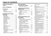
... Shift pedal ...4-4 Brake lever ...4-4 Brake pedal ...4-4 Fuel tank cap ...4-5 Fuel ...4-5 Fuel cock ...4-7 Starter (choke) lever ...4-8 Steering lock ...4-8 Rider seat ...4-9 Helmet holder ...4-9 Adjusting the shock absorber assemblies ...4-10 Sidestand ...4-10 Ignition circuit cut-off system ...4-11 OPERATION AND IMPORTANT RIDING POINTS ...6-1 Starting and warming up a cold engine ...6-1 Starting a warm engine ...6-2 Shifting ...6-2 Engine break-in ...6-4 Parking ...6-4 PERIODIC MAINTENANCE AND ADJUSTMENT ...7-1 Owner's tool kit ...7-2 Periodic maintenance chart for the emission control...
... Shift pedal ...4-4 Brake lever ...4-4 Brake pedal ...4-4 Fuel tank cap ...4-5 Fuel ...4-5 Fuel cock ...4-7 Starter (choke) lever ...4-8 Steering lock ...4-8 Rider seat ...4-9 Helmet holder ...4-9 Adjusting the shock absorber assemblies ...4-10 Sidestand ...4-10 Ignition circuit cut-off system ...4-11 OPERATION AND IMPORTANT RIDING POINTS ...6-1 Starting and warming up a cold engine ...6-1 Starting a warm engine ...6-2 Shifting ...6-2 Engine break-in ...6-4 Parking ...6-4 PERIODIC MAINTENANCE AND ADJUSTMENT ...7-1 Owner's tool kit ...7-2 Periodic maintenance chart for the emission control...
Owners Manual
Page 7
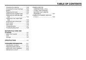
...the wheel bearings ...7-28 Battery ...7-29 Replacing the fuses ...7-30 Replacing the headlight bulb ...7-31 Replacing the tail/brake light bulb ...7-32 Replacing a turn signal light bulb ...7-33 Supporting the motorcycle ...7-33 Front wheel ...7-34 Rear wheel ...7-36 Troubleshooting ...7-37 Troubleshooting chart ...7-38 MOTORCYCLE CARE AND STORAGE ...8-1 Matte color caution ...8-1 Care ...8-1 Storage ...8-3 SPECIFICATIONS ...9-1 CONSUMER INFORMATION...10-1 Identification numbers ...10-1 Reporting safety defects ...10-3 Motorcycle noise regulation ...10-4 Maintenance record ...10-5 YAMAHA MOTOR...
...the wheel bearings ...7-28 Battery ...7-29 Replacing the fuses ...7-30 Replacing the headlight bulb ...7-31 Replacing the tail/brake light bulb ...7-32 Replacing a turn signal light bulb ...7-33 Supporting the motorcycle ...7-33 Front wheel ...7-34 Rear wheel ...7-36 Troubleshooting ...7-37 Troubleshooting chart ...7-38 MOTORCYCLE CARE AND STORAGE ...8-1 Matte color caution ...8-1 Care ...8-1 Storage ...8-3 SPECIFICATIONS ...9-1 CONSUMER INFORMATION...10-1 Identification numbers ...10-1 Reporting safety defects ...10-3 Motorcycle noise regulation ...10-4 Maintenance record ...10-5 YAMAHA MOTOR...
Owners Manual
Page 12
... bags, duffel bags, or tents, can adversely affect stability and handling if the weight distribution of accessories not sold by Yamaha for your load (suspension-adjustable models only), and check the condition and pressure of an overloaded vehicle could cause an accident. Make sure that these aftermarket companies produce. Yamaha is changed. Use extra care when riding a motorcycle that has added cargo...
... bags, duffel bags, or tents, can adversely affect stability and handling if the weight distribution of accessories not sold by Yamaha for your load (suspension-adjustable models only), and check the condition and pressure of an overloaded vehicle could cause an accident. Make sure that these aftermarket companies produce. Yamaha is changed. Use extra care when riding a motorcycle that has added cargo...
Owners Manual
Page 13
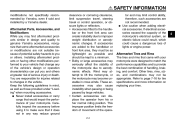
... control operation, or obscure lights or reflectors. • Accessories fitted to the handlebar or the front fork area can create instability due to improper weight distribution or aerodynamic changes. If electrical accessories exceed the capacity of the motorcycle's electrical system, an electric failure could result, which could cause a dangerous loss of lights or engine power. 2 Aftermarket Tires and Rims The tires and rims that would impair the performance of handling, braking...
... control operation, or obscure lights or reflectors. • Accessories fitted to the handlebar or the front fork area can create instability due to improper weight distribution or aerodynamic changes. If electrical accessories exceed the capacity of the motorcycle's electrical system, an electric failure could result, which could cause a dangerous loss of lights or engine power. 2 Aftermarket Tires and Rims The tires and rims that would impair the performance of handling, braking...
Owners Manual
Page 15
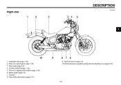
Owner's tool kit (page 7-2) 10.Shock absorber assembly spring preload adjusting ring (page 4-10) DESCRIPTION EAU10420 Right view 3 1. 2. 3. 4. 5. 6. 7. 8. Tail/brake light (page 7-32) Rear turn signal lights (page 7-33) Rider seat (page 4-9) Air filter element (page 7-13) Front turn signal/position lights (page 7-33) Brake pedal (page 4-4) Footrest Rear brake light switch (page 7-21) 3-2 9.
Owner's tool kit (page 7-2) 10.Shock absorber assembly spring preload adjusting ring (page 4-10) DESCRIPTION EAU10420 Right view 3 1. 2. 3. 4. 5. 6. 7. 8. Tail/brake light (page 7-32) Rear turn signal lights (page 7-33) Rider seat (page 4-9) Air filter element (page 7-13) Front turn signal/position lights (page 7-33) Brake pedal (page 4-4) Footrest Rear brake light switch (page 7-21) 3-2 9.
Owners Manual
Page 17
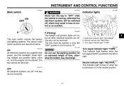
... parking position for an extended length of control or an accident. EAU10810 Indicator lights The main switch controls the ignition and lighting systems. The various main switch positions are off . Turn signal indicator light "TURN" This indicator light flashes when the turn the key to "OFF" while the vehicle is moving, otherwise the electrical systems will be switched off, which may result in loss of time, otherwise the battery may discharge. The key...
... parking position for an extended length of control or an accident. EAU10810 Indicator lights The main switch controls the ignition and lighting systems. The various main switch positions are off . Turn signal indicator light "TURN" This indicator light flashes when the turn the key to "OFF" while the vehicle is moving, otherwise the electrical systems will be switched off, which may result in loss of time, otherwise the battery may discharge. The key...
Owners Manual
Page 18
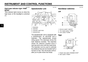
... used to plan future fuel stops. Start switch "START" 4-2 Dimmer switch "LIGHTS" 2. Turn signal switch "TURN" 3. The tripmeter can be traveled with a full tank of the headlight is equipped with the reset knob. Right 1. Odometer Tripmeter Tripmeter reset knob Speedometer 1. The odometer shows the total distance traveled. Engine stop switch "ENGINE STOP" 2. Horn switch "HORN" The speedometer unit is switched on. The speedometer shows riding speed. INSTRUMENT AND CONTROL FUNCTIONS EAU11090 EAU11630...
... used to plan future fuel stops. Start switch "START" 4-2 Dimmer switch "LIGHTS" 2. Turn signal switch "TURN" 3. The tripmeter can be traveled with a full tank of the headlight is equipped with the reset knob. Right 1. Odometer Tripmeter Tripmeter reset knob Speedometer 1. The odometer shows the total distance traveled. Engine stop switch "ENGINE STOP" 2. Horn switch "HORN" The speedometer unit is switched on. The speedometer shows riding speed. INSTRUMENT AND CONTROL FUNCTIONS EAU11090 EAU11630...
Owners Manual
Page 19
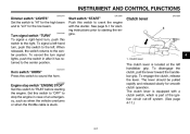
... lever should be pulled rapidly and released slowly for starting instructions prior to "RUN" before starting the engine. EAU12650 Engine stop the engine in after it has returned to the left. The clutch lever is equipped with the starter. The clutch lever is located at the left -hand turn signal lights, push the switch in case of the ignition circuit cut-off system. (See page...
... lever should be pulled rapidly and released slowly for starting instructions prior to "RUN" before starting the engine. EAU12650 Engine stop the engine in after it has returned to the left. The clutch lever is equipped with the starter. The clutch lever is located at the left -hand turn signal lights, push the switch in case of the ignition circuit cut-off system. (See page...
Owners Manual
Page 22
...). Handle gasoline with a clean, dry, soft cloth, since fuel may deteriorate painted surfaces or plastic parts. [ECA10071] 4. Gasohol There are two types of unleaded fuel will cause severe damage to internal engine parts, such as the valves and piston rings, as well as to securely close the fuel tank cap. Your Yamaha engine has been designed to the fuel system or vehicle performance problems. NOTICE...
...). Handle gasoline with a clean, dry, soft cloth, since fuel may deteriorate painted surfaces or plastic parts. [ECA10071] 4. Gasohol There are two types of unleaded fuel will cause severe damage to internal engine parts, such as the valves and piston rings, as well as to securely close the fuel tank cap. Your Yamaha engine has been designed to the fuel system or vehicle performance problems. NOTICE...
Owners Manual
Page 31
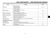
...SAFETY - Lubricate if necessary. Check air pressure. CHECKS PAGE Drive chain 7-23, 7-25 Wheels and tires 7-16, 7-18 Brake and shift pedals Brake and clutch levers Sidestand Chassis fasteners Instruments, lights, signals and switches Sidestand switch Battery...ignition circuit cut-off system. • If system is not working correctly, have Yamaha dealer check vehicle. • Check fluid level. • Fill with distilled water if necessary. 7-26 7-26 7-27 - - 4-10 7-29 5 5-3 Check for damage. PRE-OPERATION CHECKS ITEM Check chain slack. Adjust if necessary. Check tire condition...
...SAFETY - Lubricate if necessary. Check air pressure. CHECKS PAGE Drive chain 7-23, 7-25 Wheels and tires 7-16, 7-18 Brake and shift pedals Brake and clutch levers Sidestand Chassis fasteners Instruments, lights, signals and switches Sidestand switch Battery...ignition circuit cut-off system. • If system is not working correctly, have Yamaha dealer check vehicle. • Check fluid level. • Fill with distilled water if necessary. 7-26 7-26 7-27 - - 4-10 7-29 5 5-3 Check for damage. PRE-OPERATION CHECKS ITEM Check chain slack. Adjust if necessary. Check tire condition...
Owners Manual
Page 32
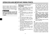
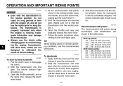
... battery. Turn the fuel cock lever to check the electrical circuit. 4. Turn the key to "ON" and make sure that the engine stop switch is warm when it responds normally to the throttle with the clutch lever pulled and the sidestand up. Shift the transmission into the neutral position. (See page 6-2.) The neutral indicator light should be met: G The transmission is cold! [ECA11131] 7. Turn the starter (choke) on . G The transmission...
... battery. Turn the fuel cock lever to check the electrical circuit. 4. Turn the key to "ON" and make sure that the engine stop switch is warm when it responds normally to the throttle with the clutch lever pulled and the sidestand up. Shift the transmission into the neutral position. (See page 6-2.) The neutral indicator light should be met: G The transmission is cold! [ECA11131] 7. Turn the starter (choke) on . G The transmission...
Owners Manual
Page 34
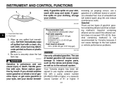
.... 2. EAU16720 Recommended shift points The recommended shift points during acceleration and deceleration are not designed to avoid damaging the engine, transmission, and drive train, which are shown in the following table, close the throttle, and at the same time, release the clutch lever slowly. Pull the clutch lever to stall or runs very roughly, pull the clutch lever in the neutral position, do...
.... 2. EAU16720 Recommended shift points The recommended shift points during acceleration and deceleration are not designed to avoid damaging the engine, transmission, and drive train, which are shown in the following table, close the throttle, and at the same time, release the clutch lever slowly. Pull the clutch lever to stall or runs very roughly, pull the clutch lever in the neutral position, do...
Owners Manual
Page 38
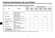
... maintenance chart for damage. • Replace if necessary. √ 2 Spark plugs √ Replace. √ Replace. √ 3 * Valve clearance Crankcase breather system Idle speed √ √ √ √ √ √ 4 * 7 5 * √ √ √ √ √ √ √ √ 6 * Exhaust system Evaporative emission control system (For California only) 7 * √ √ * Since these items require special tools, data and technical skills, have a Yamaha dealer perform the service...
... maintenance chart for damage. • Replace if necessary. √ 2 Spark plugs √ Replace. √ Replace. √ 3 * Valve clearance Crankcase breather system Idle speed √ √ √ √ √ √ 4 * 7 5 * √ √ √ √ √ √ √ √ 6 * Exhaust system Evaporative emission control system (For California only) 7 * √ √ * Since these items require special tools, data and technical skills, have a Yamaha dealer perform the service...
Owners Manual
Page 40
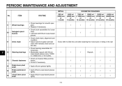
...-based grease lightly. 10 * Swingarm pivot bushes √ √ √ √ 11 Drive chain Every 300 mi (500 km) and after washing the motorcycle or riding in the rain 7 12 * Steering bearings √ √ √ Repack. √ √ 13 * Chassis fasteners Brake lever pivot shaft Brake pedal pivot shaft Clutch lever pivot shaft 14 15 16 7-5 PERIODIC MAINTENANCE AND...
...-based grease lightly. 10 * Swingarm pivot bushes √ √ √ √ 11 Drive chain Every 300 mi (500 km) and after washing the motorcycle or riding in the rain 7 12 * Steering bearings √ √ √ Repack. √ √ 13 * Chassis fasteners Brake lever pivot shaft Brake pedal pivot shaft Clutch lever pivot shaft 14 15 16 7-5 PERIODIC MAINTENANCE AND...
Owners Manual
Page 67
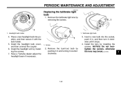
.... PERIODIC MAINTENANCE AND ADJUSTMENT EAU24133 Replacing the tail/brake light bulb 1. Tail/brake light bulb 4. Have a Yamaha dealer adjust the headlight beam if necessary. 1. Headlight bulb holder 1. Remove the tail/brake light lens by installing the screws. 7. Screw 2. Install the lens by pushing it in , and then turn it clockwise until it stops. 4. NOTICE: Do not overtighten the screws, otherwise the lens may break. [ECA10681] 7 7-32 Install the headlight bulb cover...
.... PERIODIC MAINTENANCE AND ADJUSTMENT EAU24133 Replacing the tail/brake light bulb 1. Tail/brake light bulb 4. Have a Yamaha dealer adjust the headlight beam if necessary. 1. Headlight bulb holder 1. Remove the tail/brake light lens by installing the screws. 7. Screw 2. Install the lens by pushing it in , and then turn it clockwise until it stops. 4. NOTICE: Do not overtighten the screws, otherwise the lens may break. [ECA10681] 7 7-32 Install the headlight bulb cover...
Owners Manual
Page 77
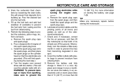
.... Remove the spark plug caps and spark plugs. Pour a teaspoonful of the sidestand/centerstand. For more than 30 8-4 8 Alternatively, turn the wheels a little every month in an excessively cold or warm place [less than 0 °C (30 °F) or more information on the cylinder head so that both of its wheels are grounded. (This will limit sparking during the next step.) d. Cover the muffler outlets with oil.) WARNING!
.... Remove the spark plug caps and spark plugs. Pour a teaspoonful of the sidestand/centerstand. For more than 30 8-4 8 Alternatively, turn the wheels a little every month in an excessively cold or warm place [less than 0 °C (30 °F) or more information on the cylinder head so that both of its wheels are grounded. (This will limit sparking during the next step.) d. Cover the muffler outlets with oil.) WARNING!
Owners Manual
Page 78
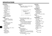
... Manufacturer/model: DENSO/U20FS-U Spark plug gap: 0.6-0.7 mm (0.024-0.028 in) Clutch: Clutch type: Wet, multiple-disc Weight: With oil and fuel: XV250Y 147.0 kg (324 lb) XV250YC 148.0 kg (326 lb) Engine: Engine type: Air cooled 4-stroke, SOHC Cylinder arrangement: V-type 2-cylinder Displacement: 249.0 cm³ Bore × stroke: 49.0 × 66.0 mm (1.93 × 2.60 in) Compression ratio: 10.00 :1 Starting system: Electric starter Lubrication...
... Manufacturer/model: DENSO/U20FS-U Spark plug gap: 0.6-0.7 mm (0.024-0.028 in) Clutch: Clutch type: Wet, multiple-disc Weight: With oil and fuel: XV250Y 147.0 kg (324 lb) XV250YC 148.0 kg (326 lb) Engine: Engine type: Air cooled 4-stroke, SOHC Cylinder arrangement: V-type 2-cylinder Displacement: 249.0 cm³ Bore × stroke: 49.0 × 66.0 mm (1.93 × 2.60 in) Compression ratio: 10.00 :1 Starting system: Electric starter Lubrication...
Owners Manual
Page 87
... charge, repair or replace any failures caused by Yamaha due to normal wear or routine maintenance. EMISSION CONTROL SYSTEM WARRANTY: Yamaha Motor Corporation, U.S.A. In order for the period of the product's warranty period. THE PERIOD OF WARRANTY for Yamaha motorcycles originally equipped with headlight, stoplight, and turn signals shall be inspected and registered for inspection and repairs at such dealer's place of sale with no mileage limitation...
... charge, repair or replace any failures caused by Yamaha due to normal wear or routine maintenance. EMISSION CONTROL SYSTEM WARRANTY: Yamaha Motor Corporation, U.S.A. In order for the period of the product's warranty period. THE PERIOD OF WARRANTY for Yamaha motorcycles originally equipped with headlight, stoplight, and turn signals shall be inspected and registered for inspection and repairs at such dealer's place of sale with no mileage limitation...
Owners Manual
Page 88
... have under warranty. Each Yamaha motorcycle dealer is limited to : 1. A. However, if a particular failure is compiled from the purchase registrations sent to second owners? Q. What responsibility does my dealer have purchased your new motorcycle, please advise us of normal maintenance services, non-warranty repairs, accident and collision damages, and oil, oil filters, air filters, spark plugs, and brake shoes. The unit has to any specific questions...
... have under warranty. Each Yamaha motorcycle dealer is limited to : 1. A. However, if a particular failure is compiled from the purchase registrations sent to second owners? Q. What responsibility does my dealer have purchased your new motorcycle, please advise us of normal maintenance services, non-warranty repairs, accident and collision damages, and oil, oil filters, air filters, spark plugs, and brake shoes. The unit has to any specific questions...
Owners Manual
Page 91
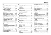
... Maintenance record ...10-5 Matte color, caution...8-1 Model label...10-2 D Dimmer switch ...4-3 Drive chain, cleaning and lubricating...7-25 Drive chain slack ...7-23 T Tail/brake light bulb, replacing ...7-32 Throttle cable free play, checking ...7-15 Throttle grip and cable, checking and lubricating ...7-26 Tires...7-16 Tool kit ...7-2 Troubleshooting ...7-37 Troubleshooting chart ...7-38 E Engine break-in ...6-4 Engine idling speed, checking ...7-15 Engine oil and oil filter element...7-10 Engine, starting a warm...6-2 Engine stop switch...4-3 N Neutral indicator light ...4-1 Noise...
... Maintenance record ...10-5 Matte color, caution...8-1 Model label...10-2 D Dimmer switch ...4-3 Drive chain, cleaning and lubricating...7-25 Drive chain slack ...7-23 T Tail/brake light bulb, replacing ...7-32 Throttle cable free play, checking ...7-15 Throttle grip and cable, checking and lubricating ...7-26 Tires...7-16 Tool kit ...7-2 Troubleshooting ...7-37 Troubleshooting chart ...7-38 E Engine break-in ...6-4 Engine idling speed, checking ...7-15 Engine oil and oil filter element...7-10 Engine, starting a warm...6-2 Engine stop switch...4-3 N Neutral indicator light ...4-1 Noise...