
Owners Manual
Page 6
... Drive select lever...4-15 Fuel tank cap...4-15 Doors ...4-16 Seats ...4-16 Seat belts...4-17 2 3 4 Glove compartment ...4-18 Cup holders...4-18 Cargo bed ...4-19 Front and rear shock absorber adjustment (YXR7FY/ YXR7FDUY/YXR7FHY/ YXR7FSEY)...4-21 Adjusting the front shock absorber assemblies (YXR7FSPY) ...4-23 Adjusting the rear shock absorber assemblies (YXR7FSPY) ...4-29 Trailer hitch bracket and receiver ...4-34 Auxiliary DC jack...4-35 5 FOR YOUR SAFETY - PRE-OPERATION CHECKS ...5-1 Front and rear brakes ...5-3 Fuel ...5-4 Engine oil ...5-6 Coolant...5-7 Final gear oil...
... Drive select lever...4-15 Fuel tank cap...4-15 Doors ...4-16 Seats ...4-16 Seat belts...4-17 2 3 4 Glove compartment ...4-18 Cup holders...4-18 Cargo bed ...4-19 Front and rear shock absorber adjustment (YXR7FY/ YXR7FDUY/YXR7FHY/ YXR7FSEY)...4-21 Adjusting the front shock absorber assemblies (YXR7FSPY) ...4-23 Adjusting the rear shock absorber assemblies (YXR7FSPY) ...4-29 Trailer hitch bracket and receiver ...4-34 Auxiliary DC jack...4-35 5 FOR YOUR SAFETY - PRE-OPERATION CHECKS ...5-1 Front and rear brakes ...5-3 Fuel ...5-4 Engine oil ...5-6 Coolant...5-7 Final gear oil...
Owners Manual
Page 7
... ...5-8 Seat belts ...5-8 Steering...5-8 Fittings and fasteners...5-8 Lights...5-9 Switches...5-9 Control cables ...5-9 Tires ...5-9 6 OPERATION...6-1 Engine break-in...6-1 Starting the engine...6-2 Drive select lever operation and reverse driving...6-4 On-Command four-wheel-drive switch and differential gear lock switch ...6-6 Parking ...6-8 Loading ...6-9 BASIC GUIDE FOR SAFE USE...7-1 KNOW YOUR VEHICLE...7-1 Driver requirements ...7-3 7 Passenger requirements ...7-4 Occupant protection system...7-4 Protective structure...7-6 Seat belts...7-6 Doors ...7-9 Passenger handholds...7-9 Seat and...
... ...5-8 Seat belts ...5-8 Steering...5-8 Fittings and fasteners...5-8 Lights...5-9 Switches...5-9 Control cables ...5-9 Tires ...5-9 6 OPERATION...6-1 Engine break-in...6-1 Starting the engine...6-2 Drive select lever operation and reverse driving...6-4 On-Command four-wheel-drive switch and differential gear lock switch ...6-6 Parking ...6-8 Loading ...6-9 BASIC GUIDE FOR SAFE USE...7-1 KNOW YOUR VEHICLE...7-1 Driver requirements ...7-3 7 Passenger requirements ...7-4 Occupant protection system...7-4 Protective structure...7-6 Seat belts...7-6 Doors ...7-9 Passenger handholds...7-9 Seat and...
Owners Manual
Page 8
...Owner's manual and tool kit...8-2 Periodic maintenance chart for the emission control system...8-4 General maintenance and lubrication chart ...8-5 Hood ...8-7 Console ...8-9 Engine oil and oil filter cartridge ...8-10 Final gear oil ...8-16 Differential gear oil ...8-19 Coolant...8-21 Axle boots ...8-23 Spark plug inspection ...8-24 Cleaning the air filter element ...8-26 Drive select lever box check hose ...8-31 V-belt cooling duct check hose...8-32 V-belt case drain plug ...8-32 Cleaning the spark arrester ...8-33 Valve clearance ...8-34 Brakes...8-34 Checking the front and rear brake pads...
...Owner's manual and tool kit...8-2 Periodic maintenance chart for the emission control system...8-4 General maintenance and lubrication chart ...8-5 Hood ...8-7 Console ...8-9 Engine oil and oil filter cartridge ...8-10 Final gear oil ...8-16 Differential gear oil ...8-19 Coolant...8-21 Axle boots ...8-23 Spark plug inspection ...8-24 Cleaning the air filter element ...8-26 Drive select lever box check hose ...8-31 V-belt cooling duct check hose...8-32 V-belt case drain plug ...8-32 Cleaning the spark arrester ...8-33 Valve clearance ...8-34 Brakes...8-34 Checking the front and rear brake pads...
Owners Manual
Page 9
...EXTENDED SERVICE (Y.E.S.) ...11-7 10 Storage ...9-2 SPECIFICATIONS...10-1 11 CONSUMER INFORMATION ...11-1 Identification number records...11-1 NOISE REGULATION...11-4 MAINTENANCE RECORD ...11-5 YAMAHA MOTOR CORPORATION, U.S.A. Brake pedal and accelerator pedal lubrication ...8-41 Rear knuckle upper and lower pivot lubrication ...8-41 Steering shaft lubrication ...8-43 Wheel removal ...8-43 Tire replacement ...8-44 Wheel installation ...8-45 Battery ...8-46 Jump-starting ...8-50 Fuse replacement ...8-52 Replacing a headlight bulb ...8-54 Headlight beam adjustment ...8-57 Tail/brake light...
...EXTENDED SERVICE (Y.E.S.) ...11-7 10 Storage ...9-2 SPECIFICATIONS...10-1 11 CONSUMER INFORMATION ...11-1 Identification number records...11-1 NOISE REGULATION...11-4 MAINTENANCE RECORD ...11-5 YAMAHA MOTOR CORPORATION, U.S.A. Brake pedal and accelerator pedal lubrication ...8-41 Rear knuckle upper and lower pivot lubrication ...8-41 Steering shaft lubrication ...8-43 Wheel removal ...8-43 Tire replacement ...8-44 Wheel installation ...8-45 Battery ...8-46 Jump-starting ...8-50 Fuse replacement ...8-52 Replacing a headlight bulb ...8-54 Headlight beam adjustment ...8-57 Tail/brake light...
Owners Manual
Page 17
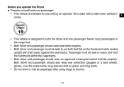
... their backs against the seat backs. Passenger must be able to carry the driver and one passenger. Both driver and passenger should wear seat belts properly. • Both driver and passenger must be able to put both feet flat on the floorboard while seated upright with a valid motor vehicle license. Before you operate the Rhino G Prepare yourself and your passenger: • This vehicle is designed to...
... their backs against the seat backs. Passenger must be able to carry the driver and one passenger. Both driver and passenger should wear seat belts properly. • Both driver and passenger must be able to put both feet flat on the floorboard while seated upright with a valid motor vehicle license. Before you operate the Rhino G Prepare yourself and your passenger: • This vehicle is designed to...
Owners Manual
Page 27
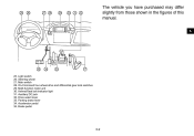
Multi-function meter unit 30. On-Command four-wheel-drive and differential gear lock switches 29. Drive select lever 33. Parking brake lever 34. O P QR S T U V The vehicle you have purchased may differ slightly from those shown in the figures of this manual. 1 2 3 4 5 6 7 Y X W G 8 9 10 11 12 13 14 25. Helmet/Seat belt indicator light 31. Main switch 28. Steering wheel 27. Auxiliary DC jack 32. Brake pedal 3-2 Light switch 26. Accelerator pedal 35.
Multi-function meter unit 30. On-Command four-wheel-drive and differential gear lock switches 29. Drive select lever 33. Parking brake lever 34. O P QR S T U V The vehicle you have purchased may differ slightly from those shown in the figures of this manual. 1 2 3 4 5 6 7 Y X W G 8 9 10 11 12 13 14 25. Helmet/Seat belt indicator light 31. Main switch 28. Steering wheel 27. Auxiliary DC jack 32. Brake pedal 3-2 Light switch 26. Accelerator pedal 35.
Owners Manual
Page 66
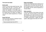
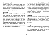
... the brakes at slow speed after starting out to see if any brake fluid is any leakage, have the vehicle inspected by a Yamaha dealer. Test the brakes at the start of the brake pedal. Add fluid if necessary. (See pages 8-36-8-37.) Recommended brake fluid: DOT 4 Brake fluid leakage Check to make sure they are applied. If there is leaking out of the pipe joints or the brake fluid...
... the brakes at slow speed after starting out to see if any brake fluid is any leakage, have the vehicle inspected by a Yamaha dealer. Test the brakes at the start of the brake pedal. Add fluid if necessary. (See pages 8-36-8-37.) Recommended brake fluid: DOT 4 Brake fluid leakage Check to make sure they are applied. If there is leaking out of the pipe joints or the brake fluid...
Owners Manual
Page 67
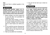
Your Yamaha engine has been designed to use a different brand of the fuel tank. 3. To avoid fires and explosions and to spill out of gasoline or premium unleaded fuel. Before refueling, turn off the engine and be sure that driver and passenger are extremely flammable. Wipe up , heat from the engine or the sun can cause injury or death. Never siphon gasoline by...
Your Yamaha engine has been designed to use a different brand of the fuel tank. 3. To avoid fires and explosions and to spill out of gasoline or premium unleaded fuel. Before refueling, turn off the engine and be sure that driver and passenger are extremely flammable. Wipe up , heat from the engine or the sun can cause injury or death. Never siphon gasoline by...
Owners Manual
Page 71
... a crash. Turn the steering wheel right and left. The seat belt must operate smoothly and spring back to the idle position fully when released. Have a Yamaha dealer repair as necessary for proper operation. Have a Yamaha dealer repair as necessary for proper operation. It must move smoothly when pulled out and retract on level ground. It must also lock up when quickly pulled out. Take the vehicle...
... a crash. Turn the steering wheel right and left. The seat belt must operate smoothly and spring back to the idle position fully when released. Have a Yamaha dealer repair as necessary for proper operation. Have a Yamaha dealer repair as necessary for proper operation. It must move smoothly when pulled out and retract on level ground. It must also lock up when quickly pulled out. Take the vehicle...
Owners Manual
Page 76
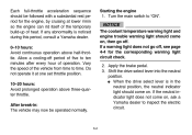
... position, the neutral indicator light should come on, then go off period of operation. Starting the engine 1. Shift the drive select lever into the neutral position. G When the drive select lever is noticed during this period, consult a Yamaha dealer. 0-10 hours: Avoid continuous operation above three-quarter throttle. Vary the speed of the vehicle from time to ten minutes after...
... position, the neutral indicator light should come on, then go off period of operation. Starting the engine 1. Shift the drive select lever into the neutral position. G When the drive select lever is noticed during this period, consult a Yamaha dealer. 0-10 hours: Avoid continuous operation above three-quarter throttle. Vary the speed of the vehicle from time to ten minutes after...
Owners Manual
Page 77
... 5 seconds on each operation of the electric starter to "START". If the engine fails to start the engine by turning the key to let it again. Each attempt should be started in any gear if the brake is cold! Do not turn the key to the "START" position with the engine running, or damage to preserve battery energy. Wait a few seconds before starting it cool. Wait at least 5 seconds between...
... 5 seconds on each operation of the electric starter to "START". If the engine fails to start the engine by turning the key to let it again. Each attempt should be started in any gear if the brake is cold! Do not turn the key to the "START" position with the engine running, or damage to preserve battery energy. Wait a few seconds before starting it cool. Wait at least 5 seconds between...
Owners Manual
Page 79
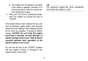
... on until the vehicle starts moving the drive select lever along the shift guide. Shift from neutral to inspect the reverse indicator light electrical circuit. 6-5 1. Take your foot off the accelerator pedal and check behind the vehicle for people or obstacles, and then release the brake pedal. 5. When it is safe to the rear while backing. Apply the brake pedal. 3. Press...
... on until the vehicle starts moving the drive select lever along the shift guide. Shift from neutral to inspect the reverse indicator light electrical circuit. 6-5 1. Take your foot off the accelerator pedal and check behind the vehicle for people or obstacles, and then release the brake pedal. 5. When it is safe to the rear while backing. Apply the brake pedal. 3. Press...
Owners Manual
Page 119
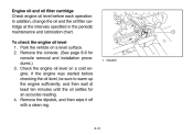
... the engine was started before each operation. Park the vehicle on a cold engine. 5B410012 Engine oil and oil filter cartridge Check engine oil level before checking the oil level, be sure to warm up the engine sufficiently, and then wait at the intervals specified in the periodic maintenance and lubrication chart. In addition, change the oil and the oil filter cartridge at least ten minutes until the oil settles for console...
... the engine was started before each operation. Park the vehicle on a cold engine. 5B410012 Engine oil and oil filter cartridge Check engine oil level before checking the oil level, be sure to warm up the engine sufficiently, and then wait at the intervals specified in the periodic maintenance and lubrication chart. In addition, change the oil and the oil filter cartridge at least ten minutes until the oil settles for console...
Owners Manual
Page 148
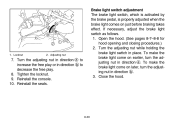
... adjusting nut while holding the brake light switch in direction b to increase the free play or in place. Adjusting nut 7. Reinstall the seats. Brake light switch adjustment The brake light switch, which is activated by the brake pedal, is properly adjusted when the brake light comes on later, turn the adjusting nut in direction b. 3. Locknut 2. Close the hood. 8-39 Turn the adjusting nut in direction a to...
... adjusting nut while holding the brake light switch in direction b to increase the free play or in place. Adjusting nut 7. Reinstall the seats. Brake light switch adjustment The brake light switch, which is activated by the brake pedal, is properly adjusted when the brake light comes on later, turn the adjusting nut in direction b. 3. Locknut 2. Close the hood. 8-39 Turn the adjusting nut in direction a to...
Owners Manual
Page 149
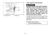
If the cables do not operate smoothly, ask a Yamaha dealer to replace them. Inspect control cables frequently and replace damaged cables. Recommended lubricant: Lithium-soap-based grease 1. Adjusting nut 8-40 Cables can result when the outer covering of control cables becomes damaged. Lubricate the cable ends. Corrosion can also become frayed or kinked. Brake light switch 2. EVU00890 Cable inspection and lubrication WARNING 1 a 2 b Damaged cables could restrict operation, which may cause an accident or injury.
If the cables do not operate smoothly, ask a Yamaha dealer to replace them. Inspect control cables frequently and replace damaged cables. Recommended lubricant: Lithium-soap-based grease 1. Adjusting nut 8-40 Cables can result when the outer covering of control cables becomes damaged. Lubricate the cable ends. Corrosion can also become frayed or kinked. Brake light switch 2. EVU00890 Cable inspection and lubrication WARNING 1 a 2 b Damaged cables could restrict operation, which may cause an accident or injury.
Owners Manual
Page 162
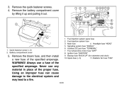
Remove the battery compartment cover by lifting it up and pulling it out. 1 2 3 4 567 8 2 @ 1 9 0 A 1. WARNING! Never use a fuse of the specified amperage. Radiator fan fuse "FAN" Battery compartment cover 5. Fuel injection system spare fuse 2. Headlight fuse "HEAD" 5. Ignition fuse "IGNITION" 9. Remove the quick fastener screws. 4. Backup fuse "BACK UP" (for odometer and clock) 10. Main fuse 4. 3. Quick fastener screw (× 2) 2. Remove the blown fuse, and then install a new fuse of the proper fuse. Always...
Remove the battery compartment cover by lifting it up and pulling it out. 1 2 3 4 567 8 2 @ 1 9 0 A 1. WARNING! Never use a fuse of the specified amperage. Radiator fan fuse "FAN" Battery compartment cover 5. Fuel injection system spare fuse 2. Headlight fuse "HEAD" 5. Ignition fuse "IGNITION" 9. Remove the quick fastener screws. 4. Backup fuse "BACK UP" (for odometer and clock) 10. Main fuse 4. 3. Quick fastener screw (× 2) 2. Remove the blown fuse, and then install a new fuse of the proper fuse. Always...
Owners Manual
Page 163
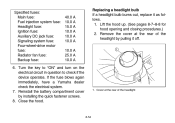
... immediately, have a Yamaha dealer check the electrical system. 7. EVU01670 Specified fuses: Main fuse: Fuel injection system fuse: Headlight fuse: Ignition fuse: Auxiliary DC jack fuse: Signaling system fuse: Four-wheel-drive motor fuse: Radiator fan fuse: Backup fuse: 40.0 A 10.0 A 15.0 A 10.0 A 10.0 A 10.0 A 10.0 A 25.0 A 10.0 A Replacing a headlight bulb If a headlight bulb burns out, replace it off. 6. Close the hood. 1. Lift the hood up. (See pages 8-7-8-8 for hood opening and closing procedures.) 2. Remove the cover at the rear of the headlight by installing the...
... immediately, have a Yamaha dealer check the electrical system. 7. EVU01670 Specified fuses: Main fuse: Fuel injection system fuse: Headlight fuse: Ignition fuse: Auxiliary DC jack fuse: Signaling system fuse: Four-wheel-drive motor fuse: Radiator fan fuse: Backup fuse: 40.0 A 10.0 A 15.0 A 10.0 A 10.0 A 10.0 A 10.0 A 25.0 A 10.0 A Replacing a headlight bulb If a headlight bulb burns out, replace it off. 6. Close the hood. 1. Lift the hood up. (See pages 8-7-8-8 for hood opening and closing procedures.) 2. Remove the cover at the rear of the headlight by installing the...
Owners Manual
Page 172
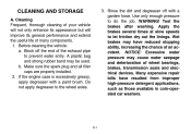
... your vehicle will not only enhance its appearance but will improve its general performance and extend the useful life of wheel bearings, brakes, transmission seals and electrical devices. A plastic bag and strong rubber band may cause water seepage and deterioration of many components. 1. Make sure the spark plug and all filler caps are properly installed. 2. Apply the brakes several times at slow speeds to prevent water entry...
... your vehicle will not only enhance its appearance but will improve its general performance and extend the useful life of wheel bearings, brakes, transmission seals and electrical devices. A plastic bag and strong rubber band may cause water seepage and deterioration of many components. 1. Make sure the spark plug and all filler caps are properly installed. 2. Apply the brakes several times at slow speeds to prevent water entry...
Owners Manual
Page 181
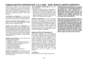
Model Specified fuses: Main fuse Fuel injection system fuse Headlight fuse Ignition fuse Auxiliary DC jack fuse Four-wheel-drive motor fuse Signaling system fuse Backup fuse Radiator fan fuse YXR7FY/YXR7FDUY/YXR7FSPY/YXR7FHY/YXR7FSEY 40.0 A 10.0 A 15.0 A 10.0 A 10.0 A 10.0 A 10.0 A 10.0 A 25.0 A 10-7
Model Specified fuses: Main fuse Fuel injection system fuse Headlight fuse Ignition fuse Auxiliary DC jack fuse Four-wheel-drive motor fuse Signaling system fuse Backup fuse Radiator fan fuse YXR7FY/YXR7FDUY/YXR7FSPY/YXR7FHY/YXR7FSEY 40.0 A 10.0 A 15.0 A 10.0 A 10.0 A 10.0 A 10.0 A 10.0 A 25.0 A 10-7
Owners Manual
Page 187
... maintenance; EVU01081 YAMAHA MOTOR CORPORATION, U.S.A. Operate and maintain the Side × Side vehicle as spark plugs, oil, oil filter, air filter, and brake pads. AND EXCLUDED FROM THIS WARRANTY. g. SPECIFIC EXCLUSIONS from the original purchaser to any subsequent purchaser(s), it not to an authorized Yamaha Side × Side Vehicle dealer of any failures caused by this warranty to the subsequent purchaser. All parts replaced under this warranty shall include parts replaced...
... maintenance; EVU01081 YAMAHA MOTOR CORPORATION, U.S.A. Operate and maintain the Side × Side vehicle as spark plugs, oil, oil filter, air filter, and brake pads. AND EXCLUDED FROM THIS WARRANTY. g. SPECIFIC EXCLUSIONS from the original purchaser to any subsequent purchaser(s), it not to an authorized Yamaha Side × Side Vehicle dealer of any failures caused by this warranty to the subsequent purchaser. All parts replaced under this warranty shall include parts replaced...