

Owners Manual
Page 5
... ...14 Oil level warning indicator ...15 Coolant temperature warning indicator ...15 Self-diagnosis device ...15 Drive select switch ...16 Engine stop switch ...16 Headlight beam switch "LIGHTS" ...17 Grip/thumb warmer adjustment switch ...17 Auxiliary DC jack (PZ50VT) ...17 Brake lever ...18 Parking brake lever ...18 Shroud latches (PZ50VT) ...18 Shroud and covers ...19 Drive guard ...20 V-belt holder (PZ50VT) ...20 Passenger grip warmer switch (PZ50VT) ...21 Backrest (PZ50VT) ...Storage pouch ...Rear carrier (PZ50VT) ...Fuel ...Suspension...
... ...14 Oil level warning indicator ...15 Coolant temperature warning indicator ...15 Self-diagnosis device ...15 Drive select switch ...16 Engine stop switch ...16 Headlight beam switch "LIGHTS" ...17 Grip/thumb warmer adjustment switch ...17 Auxiliary DC jack (PZ50VT) ...17 Brake lever ...18 Parking brake lever ...18 Shroud latches (PZ50VT) ...18 Shroud and covers ...19 Drive guard ...20 V-belt holder (PZ50VT) ...20 Passenger grip warmer switch (PZ50VT) ...21 Backrest (PZ50VT) ...Storage pouch ...Rear carrier (PZ50VT) ...Fuel ...Suspension...
Owners Manual
Page 7
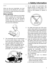
... time before operating this snowmobile. Handle fuel with another vehicle. it is released. G Never add fuel when the engine is reduced by law, and you could be dangerous to cool for use on page 31 before starting the engine. When you ride your snowmobile, you do not understand. 5. 2. 3. Check the throttle, brake, and steering for your safety. This may result if you ignore any control...
... time before operating this snowmobile. Handle fuel with another vehicle. it is released. G Never add fuel when the engine is reduced by law, and you could be dangerous to cool for use on page 31 before starting the engine. When you ride your snowmobile, you do not understand. 5. 2. 3. Check the throttle, brake, and steering for your safety. This may result if you ignore any control...
Owners Manual
Page 14
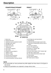
.... Low coolant temperature indicator light 27. Design and specifications are subjected to change without notice. 8 "RESET" button 12. Coolant temperature warning indicator 16. Shroud latch (PZ50VT) 9. Brake lever 2. Parking brake lever 3. Grip/thumb warmer adjustment switch 4. Auxiliary DC jack (PZ50VT) 11. "SELECT" button 13. Fuel level warning indicator 14. Oil level warning indicator 15. Speedometer 18. Odometer/tripmeter/engine speed meter 19. Fuel meter indicator 21. Drive "D" indicator light 22. Warning light 28...
.... Low coolant temperature indicator light 27. Design and specifications are subjected to change without notice. 8 "RESET" button 12. Coolant temperature warning indicator 16. Shroud latch (PZ50VT) 9. Brake lever 2. Parking brake lever 3. Grip/thumb warmer adjustment switch 4. Auxiliary DC jack (PZ50VT) 11. "SELECT" button 13. Fuel level warning indicator 14. Oil level warning indicator 15. Speedometer 18. Odometer/tripmeter/engine speed meter 19. Fuel meter indicator 21. Drive "D" indicator light 22. Warning light 28...
Owners Manual
Page 15
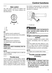
... engine can be started . Control functions ESU10291 Main switch The main switch controls the ignition and lighting systems. The various positions are described below. Regulate the speed of the drive system. When the engine has been idling for proper operation before restarting the engine. 9 NOTE: The headlights and taillight come on after the engine is idling. The key can be removed only in this position. The starter motor cranks the engine...
... engine can be started . Control functions ESU10291 Main switch The main switch controls the ignition and lighting systems. The various positions are described below. Regulate the speed of the drive system. When the engine has been idling for proper operation before restarting the engine. 9 NOTE: The headlights and taillight come on after the engine is idling. The key can be removed only in this position. The starter motor cranks the engine...

Owners Manual
Page 16
... T.O.R.S. The T.O.R.S. Throttle position sensor (throttle valve open position) 2. Throttle switch (off ) 3. The T.O.R.S. Throttle position sensor (throttle valve open position) 2. Throttle switch (off ) NOTE: G 1. Throttle cable G When the T.O.R.S. is activated, the warning light and self-diagnosis warning indicator will flash, and the two-digit code "84" will not work properly. Control functions G Be sure to the idle position when the throttle lever is released. (See page 76 for the clutch engagement speed.) Idling / starting 1. monitors the condition of...
... T.O.R.S. The T.O.R.S. Throttle position sensor (throttle valve open position) 2. Throttle switch (off ) 3. The T.O.R.S. Throttle position sensor (throttle valve open position) 2. Throttle switch (off ) NOTE: G 1. Throttle cable G When the T.O.R.S. is activated, the warning light and self-diagnosis warning indicator will flash, and the two-digit code "84" will not work properly. Control functions G Be sure to the idle position when the throttle lever is released. (See page 76 for the clutch engagement speed.) Idling / starting 1. monitors the condition of...

Owners Manual
Page 37
... wear and damage. • Replace if necessary. • Make sure that drive guard is tightened securely. • Check the drive guard mounts for damage. • Make sure that the drive guard is more than worth the time involved. PAGE 23 Engine oil 52 Coolant V-belt Drive guard 56 57 20 Brake 60 Air filter 51 31 EWS00190 WARNING If any item in a very short time; Therefore, it assures is firmly...
... wear and damage. • Replace if necessary. • Make sure that drive guard is tightened securely. • Check the drive guard mounts for damage. • Make sure that the drive guard is more than worth the time involved. PAGE 23 Engine oil 52 Coolant V-belt Drive guard 56 57 20 Brake 60 Air filter 51 31 EWS00190 WARNING If any item in a very short time; Therefore, it assures is firmly...

Owners Manual
Page 39
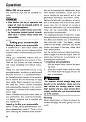
... the first time Start the engine and let it does not run roughly. The various parts in the engine wear and polish themselves to check the "SAFETY INFORMATION" section carefully before starting the engine. Turn the main switch to start position. Warm up the engine until it idle for the first 500 km (300 mi). If the engine fails to the start , release the switch, wait a few...
... the first time Start the engine and let it does not run roughly. The various parts in the engine wear and polish themselves to check the "SAFETY INFORMATION" section carefully before starting the engine. Turn the main switch to start position. Warm up the engine until it idle for the first 500 km (300 mi). If the engine fails to the start , release the switch, wait a few...
Owners Manual
Page 40
... mi) of the controls. If any engine trouble should select a large flat area to enjoy riding safely. Take the time to begin riding your snowmobile and all warning and caution labels on your feet outside the running boards. Before operating the snowmobile, read this Owner's Manual completely and understand the operation of operation, the engine oil must be operated...
... mi) of the controls. If any engine trouble should select a large flat area to enjoy riding safely. Take the time to begin riding your snowmobile and all warning and caution labels on your feet outside the running boards. Before operating the snowmobile, read this Owner's Manual completely and understand the operation of operation, the engine oil must be operated...

Owners Manual
Page 41
... of the turn and lean your weight on the running boards and leaning forward over the handlebar. (Also see "Traversing a slope".) Turning For most snow surfaces, "body English" is the key to tip. Slow down as abrupt throttle changes, excessive braking, incorrect body movements, or too much longer stopping distances. Then pull the rear of an accident. Operation EWS00220 WARNING G G Many surfaces...
... of the turn and lean your weight on the running boards and leaning forward over the handlebar. (Also see "Traversing a slope".) Turning For most snow surfaces, "body English" is the key to tip. Slow down as abrupt throttle changes, excessive braking, incorrect body movements, or too much longer stopping distances. Then pull the rear of an accident. Operation EWS00220 WARNING G G Many surfaces...

Owners Manual
Page 47
... Spark plugs Valve clearance Crankcase breather system Fuel filter Fuel line Idle speed Fuel injection • Check condition. • Adjust gap and clean. • Replace if necessary. • Check and adjust valve clearance when engine is cold. • Check breather hose for cracks or damage. • Replace if necessary. • Check condition. • Replace if necessary. • Check fuel hose for you are explained on the following pages. Periodic maintenance ESU11450 Safety...
... Spark plugs Valve clearance Crankcase breather system Fuel filter Fuel line Idle speed Fuel injection • Check condition. • Adjust gap and clean. • Replace if necessary. • Check and adjust valve clearance when engine is cold. • Check breather hose for cracks or damage. • Replace if necessary. • Check condition. • Replace if necessary. • Check fuel hose for you are explained on the following pages. Periodic maintenance ESU11450 Safety...

Owners Manual
Page 60
..., and then turn it up for removal procedure.) 4. Bottom panel 1. Place an oil pan under the oil tank to collect the used oil. 54 Insert the dipstick into the oil filler hole, and then tighten the oil filler cap. 8. Connect the oil level gauge coupler. 9. To change the engine oil (without oil filter cartridge replacement) 1. Oil level gauge coupler 2. Engine oil drain bolt (oil tank) 8. Start the engine, warm it off. 3. Periodic maintenance G G Use only 4-stroke engine oil. Install...
..., and then turn it up for removal procedure.) 4. Bottom panel 1. Place an oil pan under the oil tank to collect the used oil. 54 Insert the dipstick into the oil filler hole, and then tighten the oil filler cap. 8. Connect the oil level gauge coupler. 9. To change the engine oil (without oil filter cartridge replacement) 1. Oil level gauge coupler 2. Engine oil drain bolt (oil tank) 8. Start the engine, warm it off. 3. Periodic maintenance G G Use only 4-stroke engine oil. Install...

Owners Manual
Page 75
... to use the specified fuse. Replace the blown fuse with water. To charge the battery Have a Yamaha dealer charge the battery as soon as follows depending on the turning direction of the proper amperage. ANTIDOTE: G EXTERNAL: Flush with one of the headlight beam adjusting screws. away. Always shield your eyes when working near batteries. Remove the right side cover. (See page 45...
... to use the specified fuse. Replace the blown fuse with water. To charge the battery Have a Yamaha dealer charge the battery as soon as follows depending on the turning direction of the proper amperage. ANTIDOTE: G EXTERNAL: Flush with one of the headlight beam adjusting screws. away. Always shield your eyes when working near batteries. Remove the right side cover. (See page 45...

Owners Manual
Page 76
... maintenance Specified fuses: Main fuse: 40.0 A Fuel injection system fuse: 10.0 A "HEAD" (headlight) fuse: 20.0 A "SIG" (signal) fuse: 7.5 A "DC TERM" (auxiliary DC jack) fuse: 3.0 A "IGN" (ignition) fuse: 20.0 A "FAN" (radiator fan motor) fuse: 15.0 A "GEAR" (electric shift reverse system) fuse: 4.0 A Spare fuses: 20.0 A, 15.0 A, 7.5 A, 4.0 A, 3.0 A 4. 5. Connect the negative battery lead. Install the right side cover. 1. "HEAD" (headlight) fuse "SIG" (signal) fuse "DC TERM" (auxiliary DC jack) fuse "IGN" (ignition) fuse "FAN" (radiator fan) fuse "GEAR" (electric shift reverse system) fuse...
... maintenance Specified fuses: Main fuse: 40.0 A Fuel injection system fuse: 10.0 A "HEAD" (headlight) fuse: 20.0 A "SIG" (signal) fuse: 7.5 A "DC TERM" (auxiliary DC jack) fuse: 3.0 A "IGN" (ignition) fuse: 20.0 A "FAN" (radiator fan motor) fuse: 15.0 A "GEAR" (electric shift reverse system) fuse: 4.0 A Spare fuses: 20.0 A, 15.0 A, 7.5 A, 4.0 A, 3.0 A 4. 5. Connect the negative battery lead. Install the right side cover. 1. "HEAD" (headlight) fuse "SIG" (signal) fuse "DC TERM" (auxiliary DC jack) fuse "IGN" (ignition) fuse "FAN" (radiator fan) fuse "GEAR" (electric shift reverse system) fuse...

Owners Manual
Page 77
... the T.O.R.S. Electrical system Poor spark or no spark G Spark plugs are wet: Remove carbon or wipe the spark plugs dry. is discharged, the engine can cause electrical system damage or A FIRE HAZARD. EWS00560 WARNING G 4. malfunction: Disconnect the throttle switch connectors and connect the wire harness connectors together to the battery terminals. in tank: Supply fuel. G T.O.R.S. Troubleshooting ESU12392 G Engine turns over but does not start 1. G Clogged fuel line: Clean fuel line. Compression Insufficient G Loose cylinder head...
... the T.O.R.S. Electrical system Poor spark or no spark G Spark plugs are wet: Remove carbon or wipe the spark plugs dry. is discharged, the engine can cause electrical system damage or A FIRE HAZARD. EWS00560 WARNING G 4. malfunction: Disconnect the throttle switch connectors and connect the wire harness connectors together to the battery terminals. in tank: Supply fuel. G T.O.R.S. Troubleshooting ESU12392 G Engine turns over but does not start 1. G Clogged fuel line: Clean fuel line. Compression Insufficient G Loose cylinder head...
Owners Manual
Page 79
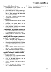
... or damaged idler wheels or shafts: Ask a Yamaha dealer to inspect. 3. 4. Problem with the correct V-belt. Loose or broken engine mount(s): Ask a Yamaha dealer to inspect. V-belt slips or becomes extremely hot 1. 2. Broken V-belt clutch components: Ask a Yamaha dealer to inspect. Worn or damaged V-belt with flat spots: Replace. Tight, loose, or broken drive chain: Ask a Yamaha dealer to inspect. Worn or damaged V-belt: Replace the Vbelt or...
... or damaged idler wheels or shafts: Ask a Yamaha dealer to inspect. 3. 4. Problem with the correct V-belt. Loose or broken engine mount(s): Ask a Yamaha dealer to inspect. V-belt slips or becomes extremely hot 1. 2. Broken V-belt clutch components: Ask a Yamaha dealer to inspect. Worn or damaged V-belt with flat spots: Replace. Tight, loose, or broken drive chain: Ask a Yamaha dealer to inspect. Worn or damaged V-belt: Replace the Vbelt or...
Owners Manual
Page 82
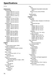
... mm (38.8 in) Rear suspension: Type: Slide rail suspension Track sprocket wheel: Material: Polyethylene Number of teeth: PZ50GT 9 PZ50MT 8 PZ50RT 9 PZ50VT 9 Transmission: Clutch type: Automatic centrifugal engagement Ratio range: 3.80-0.95 :1 Sheave distance: 267.0-270.0 mm (10.51-10.63 in) Sheave offset: 14.5-17.5 mm (0.57-0.69 in) Engine: Type: Liquid cooled 4-stroke, DOHC Cylinder arrangement: Backward-inclined parallel...
... mm (38.8 in) Rear suspension: Type: Slide rail suspension Track sprocket wheel: Material: Polyethylene Number of teeth: PZ50GT 9 PZ50MT 8 PZ50RT 9 PZ50VT 9 Transmission: Clutch type: Automatic centrifugal engagement Ratio range: 3.80-0.95 :1 Sheave distance: 267.0-270.0 mm (10.51-10.63 in) Sheave offset: 14.5-17.5 mm (0.57-0.69 in) Engine: Type: Liquid cooled 4-stroke, DOHC Cylinder arrangement: Backward-inclined parallel...

Owners Manual
Page 83
...) Battery: Model: YTX14-BS Voltage, capacity: 12 V, 12.0 Ah Ten-hour rate amperage: 1.2 A Bulb voltage, wattage × quantity: Headlight: 12 V, 60/55 W × 2 Headlight bulb type: Halogen bulb Tail/brake light: LED Meter lighting: LED High beam indicator light: LED Coolant temperature indicator light: LED Warning light: LED Low coolant temperature indicator light: LED Knock control system indicator light: LED Drive position indicator light: LED Reverse position indicator light: LED Electrical system: Ignition system: T.C.I. Spark plug: Manufacturer: NGK 77 Specifications Engagement...
...) Battery: Model: YTX14-BS Voltage, capacity: 12 V, 12.0 Ah Ten-hour rate amperage: 1.2 A Bulb voltage, wattage × quantity: Headlight: 12 V, 60/55 W × 2 Headlight bulb type: Halogen bulb Tail/brake light: LED Meter lighting: LED High beam indicator light: LED Coolant temperature indicator light: LED Warning light: LED Low coolant temperature indicator light: LED Knock control system indicator light: LED Drive position indicator light: LED Reverse position indicator light: LED Electrical system: Ignition system: T.C.I. Spark plug: Manufacturer: NGK 77 Specifications Engagement...
Owners Manual
Page 85
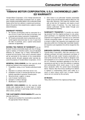
... routine maintenance including oil, spark plugs, clutch drive belts, slide runners, and track. emissions standards applicable at Yamaha's option, any failures to the machine caused by Yamaha due to faulty workmanship or material from this warranty shall include parts replaced due to conform at the time of charge, repair or replace, at the time of purchase, plus a special early-season extension (if applicable). SNOWMOBILE LIMITED WARRANTY Yamaha Motor...
... routine maintenance including oil, spark plugs, clutch drive belts, slide runners, and track. emissions standards applicable at Yamaha's option, any failures to the machine caused by Yamaha due to faulty workmanship or material from this warranty shall include parts replaced due to conform at the time of charge, repair or replace, at the time of purchase, plus a special early-season extension (if applicable). SNOWMOBILE LIMITED WARRANTY Yamaha Motor...
Owners Manual
Page 87
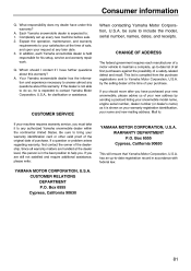
... 6555 Cypress, California 90630 81 Q. Mail to your satisfaction at the time of sale, and upon your request at the time of purchase. If a question or problem arises regarding warranty, first contact the owner of your new address by the selling dealer at any later date. ...you are handled at the dealer level, this warranty. If the dealer is not able to do so, he is compiled from the purchase registrations sent to contact Yamaha Motor Corporation, U.S.A., for his setup, service and warranty repair work. This list is expected to Yamaha Motor Corporation, U.S.A. CHANGE OF ...
... 6555 Cypress, California 90630 81 Q. Mail to your satisfaction at the time of sale, and upon your request at the time of purchase. If a question or problem arises regarding warranty, first contact the owner of your new address by the selling dealer at any later date. ...you are handled at the dealer level, this warranty. If the dealer is not able to do so, he is compiled from the purchase registrations sent to contact Yamaha Motor Corporation, U.S.A., for his setup, service and warranty repair work. This list is expected to Yamaha Motor Corporation, U.S.A. CHANGE OF ...

Owners Manual
Page 89
... ...37 Driving ...38 E Engine idling speed, adjusting ...49 Engine oil and oil filter cartridge ...52 Engine overheating prevention system ...9 Engine stop switch ...16 F Fittings and fasteners...69 Front shock absorber air pressure, adjusting (PZ50RT)...25 Fuel ...22 Fuel level warning indicator...14 Fuel meter and grip/ thumb warmer level indicator...13 Fuse, replacing...69 G General maintenance and lubrication chart ...43 Grip/thumb warmer adjustment switch...17 H Headlight beam switch ...17 Headlight beams, adjusting...69 Headlight bulb, replacing...67 High...
... ...37 Driving ...38 E Engine idling speed, adjusting ...49 Engine oil and oil filter cartridge ...52 Engine overheating prevention system ...9 Engine stop switch ...16 F Fittings and fasteners...69 Front shock absorber air pressure, adjusting (PZ50RT)...25 Fuel ...22 Fuel level warning indicator...14 Fuel meter and grip/ thumb warmer level indicator...13 Fuse, replacing...69 G General maintenance and lubrication chart ...43 Grip/thumb warmer adjustment switch...17 H Headlight beam switch ...17 Headlight beams, adjusting...69 Headlight bulb, replacing...67 High...