
Owners Manual
Page 6
... spark plugs ...6-9 Canister (for California only) ...6-10 Engine oil and oil filter cartridge ...6-11 Final gear oil ...6-14 Coolant ...6-15 Cleaning the air filter element ...6-18 Carburetors ...6-19 Checking the throttle cable free play ...6-19 Valve clearance ...6-20 Tires ...6-20 Cast wheels ...6-22 Accessories and replacement parts ...6-23 Clutch lever ...6-23 Adjusting the brake lever free play ...6-24 Adjusting the rear brake light switch ...6-24 Checking the front and rear brake pads ...6-25 Checking the brake and clutch fluid...
... spark plugs ...6-9 Canister (for California only) ...6-10 Engine oil and oil filter cartridge ...6-11 Final gear oil ...6-14 Coolant ...6-15 Cleaning the air filter element ...6-18 Carburetors ...6-19 Checking the throttle cable free play ...6-19 Valve clearance ...6-20 Tires ...6-20 Cast wheels ...6-22 Accessories and replacement parts ...6-23 Clutch lever ...6-23 Adjusting the brake lever free play ...6-24 Adjusting the rear brake light switch ...6-24 Checking the front and rear brake pads ...6-25 Checking the brake and clutch fluid...
Owners Manual
Page 7
... WARRANTY ...9-7 YAMAHA EXTENDED SERVICE (Y.E.S.) ...9-9 TABLE OF CONTENTS Checking the wheel bearings ...6-30 Battery ...6-31 Replacing the fuses ...6-33 Replacing the headlight bulb ...6-34 Replacing a turn signal light bulb or the tail/brake light bulb ...6-35 Front wheel ...6-36 Rear wheel ...6-37 Troubleshooting ...6-39 Troubleshooting charts ...6-40 MOTORCYCLE CARE AND STORAGE ...7-1 Care ...7-1 Storage ...7-3 SPECIFICATIONS ...8-1 CONSUMER INFORMATION...9-1 Identification numbers ...9-1 Reporting safety defects ...9-3 Motorcycle noise regulation ...9-4 Maintenance record ...9-5 YAMAHA...
... WARRANTY ...9-7 YAMAHA EXTENDED SERVICE (Y.E.S.) ...9-9 TABLE OF CONTENTS Checking the wheel bearings ...6-30 Battery ...6-31 Replacing the fuses ...6-33 Replacing the headlight bulb ...6-34 Replacing a turn signal light bulb or the tail/brake light bulb ...6-35 Front wheel ...6-36 Rear wheel ...6-37 Troubleshooting ...6-39 Troubleshooting charts ...6-40 MOTORCYCLE CARE AND STORAGE ...7-1 Care ...7-1 Storage ...7-3 SPECIFICATIONS ...8-1 CONSUMER INFORMATION...9-1 Identification numbers ...9-1 Reporting safety defects ...9-3 Motorcycle noise regulation ...9-4 Maintenance record ...9-5 YAMAHA...
Owners Manual
Page 10
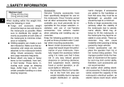
... that it to the handlebar, front fork, or front fender. Check accessory mounts and cargo restraints frequently. Use extreme caution when selecting and installing any way reduce ground clearance or cornering clearance, limit suspension travel, steering travel or control operation, or obscure lights or reflectors. If electrical accessories exceed the capacity of the motorcycle due to minimize imbalance or instability. These...
... that it to the handlebar, front fork, or front fender. Check accessory mounts and cargo restraints frequently. Use extreme caution when selecting and installing any way reduce ground clearance or cornering clearance, limit suspension travel, steering travel or control operation, or obscure lights or reflectors. If electrical accessories exceed the capacity of the motorcycle due to minimize imbalance or instability. These...
Owners Manual
Page 11
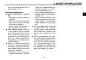
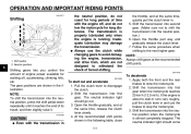
... and water and change your motorcycle in a place where pedestrians or children are poisonous and may be hot, therefore, park the G G G G G G G motorcycle in an area that it run for any gasoline, inhale a lot of lights or engine power. Always operate your clothes. When transporting the motorcycle in another vehicle, make sure that has adequate ventilation. SAFETY INFORMATION could catch fire.
... and water and change your motorcycle in a place where pedestrians or children are poisonous and may be hot, therefore, park the G G G G G G G motorcycle in an area that it run for any gasoline, inhale a lot of lights or engine power. Always operate your clothes. When transporting the motorcycle in another vehicle, make sure that has adequate ventilation. SAFETY INFORMATION could catch fire.
Owners Manual
Page 17
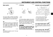
... key must be started. Turn signal indicator light "TURN" 3. Oil level warning light "OIL LEVEL" EAU11040 CAUTION: Do not use the parking position for an extended length of time, otherwise the battery may discharge. Turn. Turn signal indicator light "TURN" This indicator light flashes when the turn signal switch is in from the "OFF" position to be removed. Neutral indicator light "NEUTRAL" This indicator light comes on , and the engine can be turned to the left or right. INSTRUMENT AND CONTROL FUNCTIONS...
... key must be started. Turn signal indicator light "TURN" 3. Oil level warning light "OIL LEVEL" EAU11040 CAUTION: Do not use the parking position for an extended length of time, otherwise the battery may discharge. Turn. Turn signal indicator light "TURN" This indicator light flashes when the turn signal switch is in from the "OFF" position to be removed. Neutral indicator light "NEUTRAL" This indicator light comes on , and the engine can be turned to the left or right. INSTRUMENT AND CONTROL FUNCTIONS...

Owners Manual
Page 18
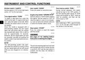
... to plan future fuel stops. 3-2 If the warning light does not come on , have a Yamaha dealer check the electrical circuit. NOTE: Even if the oil level is sufficient, the warning light may flicker when riding on when the engine oil level is low. Fuel level warning light "FUEL" This warning light comes on . Shift the transmission into the neutral position or pull the clutch lever. 3. If the warning light does not come...
... to plan future fuel stops. 3-2 If the warning light does not come on , have a Yamaha dealer check the electrical circuit. NOTE: Even if the oil level is sufficient, the warning light may flicker when riding on when the engine oil level is low. Fuel level warning light "FUEL" This warning light comes on . Shift the transmission into the neutral position or pull the clutch lever. 3. If the warning light does not come...
Owners Manual
Page 19
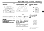
... switch "FUEL" 3. Tachometer red zone 1. Start switch "START" 3-3 Coolant temperature gauge red zone The electric tachometer allows the rider to monitor the engine speed and keep it is overheated. 1. Engine stop the vehicle and let the engine cool. (See page 6-40.) ECA10020 5 6 7 8 9 Right CAUTION: Do not operate the engine if it within the ideal power range. Dimmer switch "LIGHTS" 2. Turn signal switch "TURN" 3. INSTRUMENT AND CONTROL FUNCTIONS EAU11851 EAU12171 EAU12346 Tachometer Coolant temperature gauge Handlebar switches Left 2 3 4 1. Horn switch "HORN...
... switch "FUEL" 3. Tachometer red zone 1. Start switch "START" 3-3 Coolant temperature gauge red zone The electric tachometer allows the rider to monitor the engine speed and keep it is overheated. 1. Engine stop the vehicle and let the engine cool. (See page 6-40.) ECA10020 5 6 7 8 9 Right CAUTION: Do not operate the engine if it within the ideal power range. Dimmer switch "LIGHTS" 2. Turn signal switch "TURN" 3. INSTRUMENT AND CONTROL FUNCTIONS EAU11851 EAU12171 EAU12346 Tachometer Coolant temperature gauge Handlebar switches Left 2 3 4 1. Horn switch "HORN...
Owners Manual
Page 20
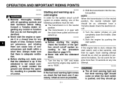
... "RUN" before starting the engine. Engine stop the engine in after the vehicle has traveled both about 150 m (490 ft) and for approximately 15 seconds. EAU42090 The oil level warning light and fuel level warning light will come on while riding, set the switch back to "ON". However, the turn , push the switch to the left -hand turn signal lights can also be kept in the fuel tank. Set this switch...
... "RUN" before starting the engine. Engine stop the engine in after the vehicle has traveled both about 150 m (490 ft) and for approximately 15 seconds. EAU42090 The oil level warning light and fuel level warning light will come on while riding, set the switch back to "ON". However, the turn , push the switch to the left -hand turn signal lights can also be kept in the fuel tank. Set this switch...
Owners Manual
Page 23
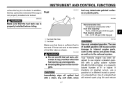
... Imp.gal) 1. EWA10880 G G WARNING Do not overfill the fuel tank, otherwise it may deteriorate painted surfaces or plastic parts. INSTRUMENT AND CONTROL FUNCTIONS unless the key is not properly installed and locked. In addition, the key cannot be removed if the cap is in the tank. EWA10130 EAU13211 Fuel fuel may overflow when the fuel warms up and expands. Your Yamaha engine has been designed to...
... Imp.gal) 1. EWA10880 G G WARNING Do not overfill the fuel tank, otherwise it may deteriorate painted surfaces or plastic parts. INSTRUMENT AND CONTROL FUNCTIONS unless the key is not properly installed and locked. In addition, the key cannot be removed if the cap is in the tank. EWA10130 EAU13211 Fuel fuel may overflow when the fuel warms up and expands. Your Yamaha engine has been designed to...
Owners Manual
Page 36
... starter (choke) on when the start the engine or operate it could contact the ground and distract the operator, resulting in a closed area for the ignition circuit cut -off system to preserve the battery. NOTE: If the engine fails to "RUN". Turn the key to the procedure described on page 3-15. Shift the transmission into the neutral position. ECA10220 CAUTION: If the fuel level warning light...
... starter (choke) on when the start the engine or operate it could contact the ground and distract the operator, resulting in a closed area for the ignition circuit cut -off system to preserve the battery. NOTE: If the engine fails to "RUN". Turn the key to the procedure described on page 3-15. Shift the transmission into the neutral position. ECA10220 CAUTION: If the fuel level warning light...
Owners Manual
Page 38
... shift gears at the same time, release the clutch lever slowly. 4. Inadequate lubrication may damage the transmission. EAU16680 the throttle, and at the same time, quickly pull the clutch lever in the illustration. Open the throttle part way and gradually release the clutch lever. 7. The neutral indicator light should go out. 3. ECA10260 the neutral position, do not tow the motorcycle for long periods of engine power available for starting...
... shift gears at the same time, release the clutch lever slowly. 4. Inadequate lubrication may damage the transmission. EAU16680 the throttle, and at the same time, quickly pull the clutch lever in the illustration. Open the throttle part way and gradually release the clutch lever. 7. The neutral indicator light should go out. 3. ECA10260 the neutral position, do not tow the motorcycle for long periods of engine power available for starting...
Owners Manual
Page 42
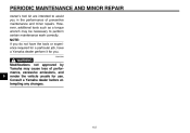
... have the tools or experience required for a particular job, have a Yamaha dealer perform it for you in the performance of performance, excessive emissions, and render the vehicle unsafe for use. Consult a Yamaha dealer before attempting any changes. 6-2 PERIODIC MAINTENANCE AND MINOR REPAIR owner's tool kit are intended to perform certain maintenance work correctly. EWA10340 1 2 3 4 5 6 7 8 9 WARNING Modifications not approved by Yamaha may be necessary to assist you .
... have the tools or experience required for a particular job, have a Yamaha dealer perform it for you in the performance of performance, excessive emissions, and render the vehicle unsafe for use. Consult a Yamaha dealer before attempting any changes. 6-2 PERIODIC MAINTENANCE AND MINOR REPAIR owner's tool kit are intended to perform certain maintenance work correctly. EWA10340 1 2 3 4 5 6 7 8 9 WARNING Modifications not approved by Yamaha may be necessary to assist you .
Owners Manual
Page 43
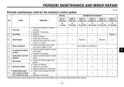
... 24 months 30 months G 1 * Fuel line G 2 * Fuel filter 3 Spark plugs G G G G 4 * Valve clearance 5 * Crankcase breather system G G G G Carburetor synchro6 * nization 7 * Idle speed 8 * Exhaust system Evaporative emis9 * sion control system (For California only) G G G G G G Check fuel hoses for leakage. Check condition. Check and adjust engine idle speed. Adjust gap and clean. PERIODIC MAINTENANCE AND MINOR REPAIR EAU17600 Periodic maintenance chart for damage. Check control system for the emission control system INITIAL No. Adjust...
... 24 months 30 months G 1 * Fuel line G 2 * Fuel filter 3 Spark plugs G G G G 4 * Valve clearance 5 * Crankcase breather system G G G G Carburetor synchro6 * nization 7 * Idle speed 8 * Exhaust system Evaporative emis9 * sion control system (For California only) G G G G G G Check fuel hoses for leakage. Check condition. Check and adjust engine idle speed. Adjust gap and clean. PERIODIC MAINTENANCE AND MINOR REPAIR EAU17600 Periodic maintenance chart for damage. Check control system for the emission control system INITIAL No. Adjust...
Owners Manual
Page 47
... km) or 36 months, repeat the maintenance intervals starting from 8000 mi (13000 km) or 12 months. Replace the oil seals on the inner parts of the brake or clutch master cylinders, caliper cylinders and clutch release cylinder every two years. G Hydraulic brake and clutch systems After disassembling the brake or clutch master cylinders, caliper cylinders or clutch release cylinder, always change the fluid. PERIODIC MAINTENANCE AND MINOR REPAIR INITIAL No. G G G 6-7 ITEM ROUTINE 600...
... km) or 36 months, repeat the maintenance intervals starting from 8000 mi (13000 km) or 12 months. Replace the oil seals on the inner parts of the brake or clutch master cylinders, caliper cylinders and clutch release cylinder every two years. G Hydraulic brake and clutch systems After disassembling the brake or clutch master cylinders, caliper cylinders or clutch release cylinder, always change the fluid. PERIODIC MAINTENANCE AND MINOR REPAIR INITIAL No. G G G 6-7 ITEM ROUTINE 600...
Owners Manual
Page 60
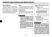
... G G 7 8 9 WARNING The tire air pressure must be checked and, if necessary, adjusted before each ride. PERIODIC MAINTENANCE AND MINOR REPAIR EAU21401 EAU32380 Valve clearance 1 2 3 4 5 6 The valve clearance changes with the total weight of rider, passenger, cargo, and accessories approved for this from side to side. Securely pack your vehicle, such as handling, braking, performance and safety. Do not carry loosely packed items that can shift. To prevent this model. Tire air pressure...
... G G 7 8 9 WARNING The tire air pressure must be checked and, if necessary, adjusted before each ride. PERIODIC MAINTENANCE AND MINOR REPAIR EAU21401 EAU32380 Valve clearance 1 2 3 4 5 6 The valve clearance changes with the total weight of rider, passenger, cargo, and accessories approved for this from side to side. Securely pack your vehicle, such as handling, braking, performance and safety. Do not carry loosely packed items that can shift. To prevent this model. Tire air pressure...
Owners Manual
Page 64
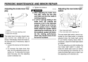
... free play and make the brake light come on just before operating the motorcycle. Locknut 2. EWA10630 EAU22270 G G The brake lever free play 1 2 3 4 5 6 7 8 9 1. WARNING After adjusting the brake lever free play, check the free play , turn the adjusting screw in direction (a). If there is working properly. PERIODIC MAINTENANCE AND MINOR REPAIR EAU22092 Adjusting the brake lever free play should measure 2.0-5.0 mm...
... free play and make the brake light come on just before operating the motorcycle. Locknut 2. EWA10630 EAU22270 G G The brake lever free play 1 2 3 4 5 6 7 8 9 1. WARNING After adjusting the brake lever free play, check the free play , turn the adjusting screw in direction (a). If there is working properly. PERIODIC MAINTENANCE AND MINOR REPAIR EAU22092 Adjusting the brake lever free play should measure 2.0-5.0 mm...
Owners Manual
Page 74
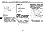
... turn off the electrical circuit in question. 2. Signaling system fuse 3. Spare fuse Specified fuses: Main fuse: 30.0 A Headlight fuse: 15.0 A Signaling system fuse: 10.0 A Radiator fan fuse: 10.0 A Ignition fuse: 10.0 A ECA10640 Replacing the headlight bulb This model is blown, replace it as follows. 1. If the fuse immediately blows again, have a Yamaha dealer check the electrical system. 1. Headlight fuse 2. Remove the headlight unit by removing the screws. Radiator fan fuse 5. CAUTION: Do not use a fuse of the specified amperage. PERIODIC MAINTENANCE AND...
... turn off the electrical circuit in question. 2. Signaling system fuse 3. Spare fuse Specified fuses: Main fuse: 30.0 A Headlight fuse: 15.0 A Signaling system fuse: 10.0 A Radiator fan fuse: 10.0 A Ignition fuse: 10.0 A ECA10640 Replacing the headlight bulb This model is blown, replace it as follows. 1. If the fuse immediately blows again, have a Yamaha dealer check the electrical system. 1. Headlight fuse 2. Remove the headlight unit by removing the screws. Radiator fan fuse 5. CAUTION: Do not use a fuse of the specified amperage. PERIODIC MAINTENANCE AND...
Owners Manual
Page 86
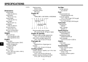
SPECIFICATIONS EAU2633H Dimensions: 1 2 3 4 5 6 7 8 9 Overall length: 2300 mm (90.6 in) Overall width: 795 mm (31.3 in) Overall height: 1160 mm (45.7 in) Seat height: 765 mm (30.1 in) Wheelbase: 1590 mm (62.6 in) Ground clearance: 145 mm (5.71 in) Minimum turning radius: 2900 mm (114.2 in) Starting system: Electric starter Lubrication system: Wet sump Air filter: Air filter element: Dry element Engine oil: Type: YAMALUBE 4, SAE10W30 or SAE20W40...
SPECIFICATIONS EAU2633H Dimensions: 1 2 3 4 5 6 7 8 9 Overall length: 2300 mm (90.6 in) Overall width: 795 mm (31.3 in) Overall height: 1160 mm (45.7 in) Seat height: 765 mm (30.1 in) Wheelbase: 1590 mm (62.6 in) Ground clearance: 145 mm (5.71 in) Minimum turning radius: 2900 mm (114.2 in) Starting system: Electric starter Lubrication system: Wet sump Air filter: Air filter element: Dry element Engine oil: Type: YAMALUBE 4, SAE10W30 or SAE20W40...
Owners Manual
Page 88
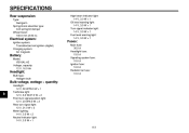
SPECIFICATIONS Rear suspension: Type: Swingarm Spring/shock absorber type: Coil spring/oil damper Wheel travel: 100.0 mm (3.94 in) High beam indicator light: 14 V, 3.0 W × 1 Oil level warning light: 14 V, 3.0 W × 1 Turn signal indicator light: 14 V, 3.0 W × 1 Fuel level warning light: 14 V, 3.0 W × 1 1 2 3 4 5 6 7 8 9 Electrical system: Ignition system: Transistorized coil ignition (digital) Charging system: AC magneto Fuses: Main fuse: 30.0 A Headlight fuse: 15.0 A Signaling system fuse: 10.0 A Ignition fuse: 10.0 A Radiator fan fuse: 10.0 A Battery: Model: YB16AL-A2 ...
SPECIFICATIONS Rear suspension: Type: Swingarm Spring/shock absorber type: Coil spring/oil damper Wheel travel: 100.0 mm (3.94 in) High beam indicator light: 14 V, 3.0 W × 1 Oil level warning light: 14 V, 3.0 W × 1 Turn signal indicator light: 14 V, 3.0 W × 1 Fuel level warning light: 14 V, 3.0 W × 1 1 2 3 4 5 6 7 8 9 Electrical system: Ignition system: Transistorized coil ignition (digital) Charging system: AC magneto Fuses: Main fuse: 30.0 A Headlight fuse: 15.0 A Signaling system fuse: 10.0 A Ignition fuse: 10.0 A Radiator fan fuse: 10.0 A Battery: Model: YB16AL-A2 ...
Owners Manual
Page 99
... R Rear brake light switch, adjusting ...6-24 Rear suspension, lubricating...6-29 Rider seat...3-9 H Handlebar switches ...3-3 Headlight bulb, replacing...6-34 Helmet holder ...3-10 High beam indicator light...3-2 Horn switch...3-4 S Safety defects, reporting ...9-3 Safety information ...1-1 Shifting ...5-3 Shift pedal ...3-5 Shock absorber assemblies, adjusting...3-12 Sidestand ...3-14 Spark plugs, checking ...6-9 Specifications ...8-1 Speedometer unit...3-2 Starter (choke) lever...3-8 Starting and warming up a cold engine...5-1 Start switch...3-4 Steering, checking...6-30 Steering lock...
... R Rear brake light switch, adjusting ...6-24 Rear suspension, lubricating...6-29 Rider seat...3-9 H Handlebar switches ...3-3 Headlight bulb, replacing...6-34 Helmet holder ...3-10 High beam indicator light...3-2 Horn switch...3-4 S Safety defects, reporting ...9-3 Safety information ...1-1 Shifting ...5-3 Shift pedal ...3-5 Shock absorber assemblies, adjusting...3-12 Sidestand ...3-14 Spark plugs, checking ...6-9 Specifications ...8-1 Speedometer unit...3-2 Starter (choke) lever...3-8 Starting and warming up a cold engine...5-1 Start switch...3-4 Steering, checking...6-30 Steering lock...