
Owners Manual
Page 7
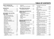
......5-4 Parking ...5-5 PERIODIC MAINTENANCE AND MINOR REPAIR ...6-1 PERIODIC MAINTENANCE ...6-1 Owner's tool kit ...6-1 Periodic maintenance chart for the emission control system ...6-3 General maintenance and lubrication chart ...6-4 Removing and installing panels ...6-8 Checking the spark plugs ...6-9 Canister (for California only) ...6-10 Engine oil and oil filter element ...6-11 Final gear oil ...6-13 Cleaning the air filter element ...6-14 Carburetors ...6-16 Checking the throttle cable free play ...6-16 Valve clearance ...6-16 Tires ...6-17 Spoke wheels ...6-20 Accessories and replacement...
......5-4 Parking ...5-5 PERIODIC MAINTENANCE AND MINOR REPAIR ...6-1 PERIODIC MAINTENANCE ...6-1 Owner's tool kit ...6-1 Periodic maintenance chart for the emission control system ...6-3 General maintenance and lubrication chart ...6-4 Removing and installing panels ...6-8 Checking the spark plugs ...6-9 Canister (for California only) ...6-10 Engine oil and oil filter element ...6-11 Final gear oil ...6-13 Cleaning the air filter element ...6-14 Carburetors ...6-16 Checking the throttle cable free play ...6-16 Valve clearance ...6-16 Tires ...6-17 Spoke wheels ...6-20 Accessories and replacement...
Owners Manual
Page 8
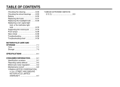
...Replacing the fuses ...6-31 Replacing the headlight bulb ...6-32 Replacing a turn signal light bulb or the tail/brake light bulb ...6-33 Supporting the motorcycle ...6-34 Front wheel ...6-35 Rear wheel ...6-36 Troubleshooting ...6-38 Troubleshooting chart ...6-39 MOTORCYCLE CARE AND STORAGE ...7-1 Care ...7-1 Storage ...7-3 SPECIFICATIONS ...8-1 CONSUMER INFORMATION ...9-1 Identification numbers ...9-1 Reporting safety defects ...9-3 Motorcycle noise regulation ...9-4 Maintenance record ...9-5 YAMAHA MOTOR CORPORATION, U.S.A. STREET AND ENDURO MOTORCYCLE LIMITED WARRANTY ...9-7 YAMAHA EXTENDED...
...Replacing the fuses ...6-31 Replacing the headlight bulb ...6-32 Replacing a turn signal light bulb or the tail/brake light bulb ...6-33 Supporting the motorcycle ...6-34 Front wheel ...6-35 Rear wheel ...6-36 Troubleshooting ...6-38 Troubleshooting chart ...6-39 MOTORCYCLE CARE AND STORAGE ...7-1 Care ...7-1 Storage ...7-3 SPECIFICATIONS ...8-1 CONSUMER INFORMATION ...9-1 Identification numbers ...9-1 Reporting safety defects ...9-3 Motorcycle noise regulation ...9-4 Maintenance record ...9-5 YAMAHA MOTOR CORPORATION, U.S.A. STREET AND ENDURO MOTORCYCLE LIMITED WARRANTY ...9-7 YAMAHA EXTENDED...
Owners Manual
Page 10
...Never touch the engine or exhaust system during operation to EXCESSIVE SPEED or undercornering (insufficient lean angle for the speed). • Always obey the speed limit and never travel faster than warranted by Yamaha, or the ...passenger should always hold onto the operator, seat strap, or grab bar, if equipped, with both hands and keep both hands on the handlebar and both feet on the passenger footrests. G Always wear an approved helmet. Modifications Modifications made to this motorcycle not approved by road and traffic conditions. • Always signal before turning or changing...
...Never touch the engine or exhaust system during operation to EXCESSIVE SPEED or undercornering (insufficient lean angle for the speed). • Always obey the speed limit and never travel faster than warranted by Yamaha, or the ...passenger should always hold onto the operator, seat strap, or grab bar, if equipped, with both hands and keep both hands on the handlebar and both feet on the passenger footrests. G Always wear an approved helmet. Modifications Modifications made to this motorcycle not approved by road and traffic conditions. • Always signal before turning or changing...
Owners Manual
Page 11
...) When loading within this motorcycle. G Shifting weights can create unstable handling or slow steering response. Never attach any accessories. Since Yamaha cannot test all other accessories that would impair the performance of the motorcycle to the handlebar, front fork, or front fender. This improper position limits the freedom of movement of the operator, passenger, accessories and cargo must not exceed the...
...) When loading within this motorcycle. G Shifting weights can create unstable handling or slow steering response. Never attach any accessories. Since Yamaha cannot test all other accessories that would impair the performance of the motorcycle to the handlebar, front fork, or front fender. This improper position limits the freedom of movement of the operator, passenger, accessories and cargo must not exceed the...
Owners Manual
Page 12
... soap and water and change your doctor immediately. G Never start the engine or let it run for manual type). The exhaust fumes are poisonous and may limit control ability, therefore, such accessories are not likely to "ON" or "RES" (for vacuum type) / "OFF" (for any gasoline on a slope or soft ground, otherwise it may leak out of the carburetor or fuel tank. When transporting...
... soap and water and change your doctor immediately. G Never start the engine or let it run for manual type). The exhaust fumes are poisonous and may limit control ability, therefore, such accessories are not likely to "ON" or "RES" (for vacuum type) / "OFF" (for any gasoline on a slope or soft ground, otherwise it may leak out of the carburetor or fuel tank. When transporting...
Owners Manual
Page 21
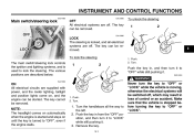
INSTRUMENT AND CONTROL FUNCTIONS EAU10460 EAU10660 Main switch/steering lock OFF All electrical systems are supplied with power, and the meter lighting, taillight and position lights come on until the key is turned to lock the steering. The key can be removed. Turn. NOTE: The headlight comes on automatically when the engine is started and stays on , and the engine can be started. Never turn the key to "OFF" or "LOCK" while the vehicle is used...
INSTRUMENT AND CONTROL FUNCTIONS EAU10460 EAU10660 Main switch/steering lock OFF All electrical systems are supplied with power, and the meter lighting, taillight and position lights come on until the key is turned to lock the steering. The key can be removed. Turn. NOTE: The headlight comes on automatically when the engine is started and stays on , and the engine can be started. Never turn the key to "OFF" or "LOCK" while the vehicle is used...
Owners Manual
Page 22
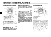
... traveled. The tripmeter can be used to plan future fuel stops. 3-2 INSTRUMENT AND CONTROL FUNCTIONS EAU11003 EAU11080 EAU11630 Indicator and warning lights High beam indicator light " " This indicator light comes on when the high beam of fuel. EAU11060 Engine trouble warning light " " This warning light comes on when the transmission is switched on. When this occurs, have a Yamaha dealer check the electrical circuit. 1. 2. 3. 4. The speedometer shows riding speed.
... traveled. The tripmeter can be used to plan future fuel stops. 3-2 INSTRUMENT AND CONTROL FUNCTIONS EAU11003 EAU11080 EAU11630 Indicator and warning lights High beam indicator light " " This indicator light comes on when the high beam of fuel. EAU11060 Engine trouble warning light " " This warning light comes on when the transmission is switched on. When this occurs, have a Yamaha dealer check the electrical circuit. 1. 2. 3. 4. The speedometer shows riding speed.
Owners Manual
Page 23
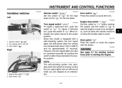
... 5-1 for starting the engine. 1. INSTRUMENT AND CONTROL FUNCTIONS EAU12345 EAU12400 EAU12500 Handlebar switches Left Dimmer switch " / " Set this switch to " " for the high beam and to " ". Horn switch " " Right Turn signal switch " / " To signal a right-hand turn signal lights can also be canceled manually by pushing the switch in case of an emergency, such as when the vehicle overturns or when the throttle cable is stuck. EAU12660 1. Turn signal switch " / " 3. Set this switch to...
... 5-1 for starting the engine. 1. INSTRUMENT AND CONTROL FUNCTIONS EAU12345 EAU12400 EAU12500 Handlebar switches Left Dimmer switch " / " Set this switch to " " for the high beam and to " ". Horn switch " " Right Turn signal switch " / " To signal a right-hand turn signal lights can also be canceled manually by pushing the switch in case of an emergency, such as when the vehicle overturns or when the throttle cable is stuck. EAU12660 1. Turn signal switch " / " 3. Set this switch to...
Owners Manual
Page 27
... or vehicle performance problems. EAU13441 EAU13550 Catalytic converter This vehicle is not recommended by Yamaha because it . Gasohol containing methanol is equipped with catalytic converters in the exhaust system. G Never park the vehicle near possible fire hazards such as follows and shown in this position when the engine is hot after operation. Always turn the fuel cock lever to this position, fuel will not flow. INSTRUMENT AND CONTROL FUNCTIONS knocking...
... or vehicle performance problems. EAU13441 EAU13550 Catalytic converter This vehicle is not recommended by Yamaha because it . Gasohol containing methanol is equipped with catalytic converters in the exhaust system. G Never park the vehicle near possible fire hazards such as follows and shown in this position when the engine is hot after operation. Always turn the fuel cock lever to this position, fuel will not flow. INSTRUMENT AND CONTROL FUNCTIONS knocking...
Owners Manual
Page 33
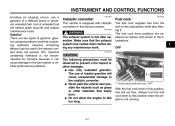
... excessive gas pressure. G Always have a Yamaha dealer service the shock absorber. Luggage strap holders Sidestand The sidestand is located on each passenger footrest. Raise the sidestand or lower it may result from improper handling. WARNING The vehicle must not be ridden with your foot while holding the vehicle upright. G Do not subject the shock absorber to an open flame or other high heat...
... excessive gas pressure. G Always have a Yamaha dealer service the shock absorber. Luggage strap holders Sidestand The sidestand is located on each passenger footrest. Raise the sidestand or lower it may result from improper handling. WARNING The vehicle must not be ridden with your foot while holding the vehicle upright. G Do not subject the shock absorber to an open flame or other high heat...
Owners Manual
Page 39
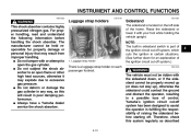
... contact the ground and distract the operator, resulting in gear with the clutch lever pulled and the sidestand up. CAUTION: The engine trouble warning light should be on when the key is not raised completely, it in the neutral position. OPERATION AND IMPORTANT RIDING POINTS EAU15950 EAU16390 EWA10270 WARNING G Starting and warming up a cold engine In order for any length of time. Turn the starter (choke...
... contact the ground and distract the operator, resulting in gear with the clutch lever pulled and the sidestand up. CAUTION: The engine trouble warning light should be on when the key is not raised completely, it in the neutral position. OPERATION AND IMPORTANT RIDING POINTS EAU15950 EAU16390 EWA10270 WARNING G Starting and warming up a cold engine In order for any length of time. Turn the starter (choke...
Owners Manual
Page 41
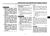
... EAU16671 Shifting XVS65W Shifting gears lets you control the amount of engine power available for starting off , and do not tow the motorcycle for long periods of time with the engine off , accelerating, climbing hills, etc. The gear positions are not designed to the next higher gear. 5 5-3 EAU16680 1. The neutral indicator light should go out. 3. Open the throttle part way and gradually release the clutch lever. 7. Shift the transmission...
... EAU16671 Shifting XVS65W Shifting gears lets you control the amount of engine power available for starting off , and do not tow the motorcycle for long periods of time with the engine off , accelerating, climbing hills, etc. The gear positions are not designed to the next higher gear. 5 5-3 EAU16680 1. The neutral indicator light should go out. 3. Open the throttle part way and gradually release the clutch lever. 7. Shift the transmission...
Owners Manual
Page 46
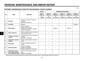
Replace. 6 4 * Valve clearance Crankcase breather system Carburetor synchronization Idle speed 5 * 6 * 7 * 8 * Exhaust system Evaporative emission control system (For California only) 9 * √ √ * Since these items require special tools, data and technical skills, have a Yamaha dealer perform the service. 6-3 PERIODIC MAINTENANCE AND MINOR REPAIR EAU17600 Periodic maintenance chart for damage. • Replace if necessary. √ √ 3 Spark plugs Replace. ITEM ROUTINE 600 mi (1000 km) or 1 month 4000 mi...
Replace. 6 4 * Valve clearance Crankcase breather system Carburetor synchronization Idle speed 5 * 6 * 7 * 8 * Exhaust system Evaporative emission control system (For California only) 9 * √ √ * Since these items require special tools, data and technical skills, have a Yamaha dealer perform the service. 6-3 PERIODIC MAINTENANCE AND MINOR REPAIR EAU17600 Periodic maintenance chart for damage. • Replace if necessary. √ √ 3 Spark plugs Replace. ITEM ROUTINE 600 mi (1000 km) or 1 month 4000 mi...
Owners Manual
Page 61
..., passenger, and accessories (cowling, saddlebags, etc. Minimum tire tread depth (front and rear): 1.0 mm (0.04 in it as soon as handling, braking, performance and safety. Make sure that can shift. Operation of your vehicle is equipped with a highquality product. 6 Tire information This motorcycle is important for several characteristics of an overloaded vehicle could cause tire damage, an accident, or even injury. Tire inspection EWA10560 WARNING G G WARNING...
..., passenger, and accessories (cowling, saddlebags, etc. Minimum tire tread depth (front and rear): 1.0 mm (0.04 in it as soon as handling, braking, performance and safety. Make sure that can shift. Operation of your vehicle is equipped with a highquality product. 6 Tire information This motorcycle is important for several characteristics of an overloaded vehicle could cause tire damage, an accident, or even injury. Tire inspection EWA10560 WARNING G G WARNING...
Owners Manual
Page 67
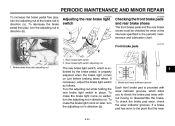
... the brake light switch as follows. To make the brake light come on just before braking takes effect. To make the brake light come on earlier, turn the adjusting nut in direction (b). 6 1. Rear brake light switch adjusting nut 1. PERIODIC MAINTENANCE AND MINOR REPAIR To increase the brake pedal free play, turn the adjusting nut in direction (b). Brake pad wear indicator groove Each front brake pad is properly adjusted when the brake light comes...
... the brake light switch as follows. To make the brake light come on just before braking takes effect. To make the brake light come on earlier, turn the adjusting nut in direction (b). 6 1. Rear brake light switch adjusting nut 1. PERIODIC MAINTENANCE AND MINOR REPAIR To increase the brake pedal free play, turn the adjusting nut in direction (b). Brake pad wear indicator groove Each front brake pad is properly adjusted when the brake light comes...
Owners Manual
Page 74
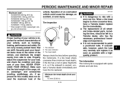
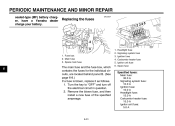
Turn the key to "OFF" and turn off the electrical circuit in question. 2. Headlight fuse Signaling system fuse Ignition fuse Carburetor heater fuse Ignitor unit fuse Spare fuse Specified fuses: Main fuse: 30.0 A Signaling system fuse: 10.0 A Ignition fuse: 10.0 A Headlight fuse: 15.0 A Carburetor heater fuse: 15.0 A Ignitor unit fuse: 5.0 A 6-31 Spare main fuse 6 The main fuse and the fuse box, which contains the fuses for the individual circuits, are located behind panel B. (See page 6-8.) If a fuse is blown, replace it as follows...
Turn the key to "OFF" and turn off the electrical circuit in question. 2. Headlight fuse Signaling system fuse Ignition fuse Carburetor heater fuse Ignitor unit fuse Spare fuse Specified fuses: Main fuse: 30.0 A Signaling system fuse: 10.0 A Ignition fuse: 10.0 A Headlight fuse: 15.0 A Carburetor heater fuse: 15.0 A Ignitor unit fuse: 5.0 A 6-31 Spare main fuse 6 The main fuse and the fuse box, which contains the fuses for the individual circuits, are located behind panel B. (See page 6-8.) If a fuse is blown, replace it as follows...
Owners Manual
Page 80
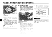
... nut: 20 Nm (2.0 m·kgf, 14 ft·lbf) 1. Install the final gear case bolts. 3. PERIODIC MAINTENANCE AND MINOR REPAIR EAU25511 To install the rear wheel 1. Adjust the brake pedal free play. (See page 6-23.) EWA10660 WARNING 1. Install the rear wheel, wheel axle, final gear case, and drive shaft by pushing the wheel forward and guiding the drive shaft into the middle gear universal joint. 7. Bolt 2. Install the panel. 6. Middle gear universal joint 2.
... nut: 20 Nm (2.0 m·kgf, 14 ft·lbf) 1. Install the final gear case bolts. 3. PERIODIC MAINTENANCE AND MINOR REPAIR EAU25511 To install the rear wheel 1. Adjust the brake pedal free play. (See page 6-23.) EWA10660 WARNING 1. Install the rear wheel, wheel axle, final gear case, and drive shaft by pushing the wheel forward and guiding the drive shaft into the middle gear universal joint. 7. Bolt 2. Install the panel. 6. Middle gear universal joint 2.
Owners Manual
Page 83
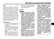
... motorcycle looking good, extend its life and optimize its performance. Do not use a quality plastic polishing compound after the engine has cooled down. 2. Make sure that all caps and covers as well as they cause water seepage and deterioration in contact with strong or abrasive cleaning products, solvent or 7-1 G thinner, fuel (gasoline), rust removers or inhibitors, brake fluid, antifreeze or...
... motorcycle looking good, extend its life and optimize its performance. Do not use a quality plastic polishing compound after the engine has cooled down. 2. Make sure that all caps and covers as well as they cause water seepage and deterioration in contact with strong or abrasive cleaning products, solvent or 7-1 G thinner, fuel (gasoline), rust removers or inhibitors, brake fluid, antifreeze or...
Owners Manual
Page 90
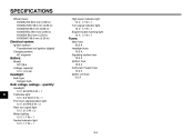
...1 Engine trouble warning light: 12 V, 1.7 W × 1 Fuses: Main fuse: 30.0 A Headlight fuse: 15.0 A Signaling system fuse: 10.0 A Ignition fuse: 10.0 A Carburetor heater fuse: 15.0 A Ignitor unit fuse: 5.0 A Electrical system: Ignition system: Transistorized coil ignition (digital) Charging system: AC magneto Battery: Model: GT12B-4 Voltage, capacity: 12 V, 10.0 Ah Headlight: Bulb type: Halogen bulb Bulb voltage, wattage × quantity: 8 Headlight: 12 V, 60 W/55.0 W × 1 Tail/brake light: 12 V, 8.0 W/27.0 W × 1 Front turn signal/position light: 12 V, 23 W/8.0 W × 2 Rear...
...1 Engine trouble warning light: 12 V, 1.7 W × 1 Fuses: Main fuse: 30.0 A Headlight fuse: 15.0 A Signaling system fuse: 10.0 A Ignition fuse: 10.0 A Carburetor heater fuse: 15.0 A Ignitor unit fuse: 5.0 A Electrical system: Ignition system: Transistorized coil ignition (digital) Charging system: AC magneto Battery: Model: GT12B-4 Voltage, capacity: 12 V, 10.0 Ah Headlight: Bulb type: Halogen bulb Bulb voltage, wattage × quantity: 8 Headlight: 12 V, 60 W/55.0 W × 1 Tail/brake light: 12 V, 8.0 W/27.0 W × 1 Front turn signal/position light: 12 V, 23 W/8.0 W × 2 Rear...
Owners Manual
Page 101
...Main switch/steering lock ...3-1 Maintenance and lubrication, periodic...6-4 Maintenance, emission control system ...6-3 Maintenance, periodic ...6-1 Maintenance record ...9-5 Model label...9-2 D Dimmer switch ...3-3 E Engine break-in ...5-4 Engine oil and oil filter element...6-11 Engine, starting a warm...5-2 Engine stop switch...3-3 Engine trouble warning light ...3-2 T Throttle cable free play, checking ...6-16 Throttle grip and cable, checking and lubricating ...6-27 Tires...6-17 Tool kit ...6-1 Troubleshooting ...6-38 N Neutral indicator light ...3-2 Noise regulation ...9-4 P Panels...
...Main switch/steering lock ...3-1 Maintenance and lubrication, periodic...6-4 Maintenance, emission control system ...6-3 Maintenance, periodic ...6-1 Maintenance record ...9-5 Model label...9-2 D Dimmer switch ...3-3 E Engine break-in ...5-4 Engine oil and oil filter element...6-11 Engine, starting a warm...5-2 Engine stop switch...3-3 Engine trouble warning light ...3-2 T Throttle cable free play, checking ...6-16 Throttle grip and cable, checking and lubricating ...6-27 Tires...6-17 Tool kit ...6-1 Troubleshooting ...6-38 N Neutral indicator light ...3-2 Noise regulation ...9-4 P Panels...