

Owners Manual
Page 7
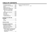
......5-4 Parking ...5-5 PERIODIC MAINTENANCE AND MINOR REPAIR ...6-1 PERIODIC MAINTENANCE ...6-1 Owner's tool kit ...6-1 Periodic maintenance chart for the emission control system ...6-3 General maintenance and lubrication chart ...6-4 Removing and installing panels ...6-8 Checking the spark plugs ...6-9 Canister (for California only) ...6-10 Engine oil and oil filter element ...6-11 Final gear oil ...6-13 Cleaning the air filter element ...6-14 Carburetors ...6-16 Checking the throttle cable free play ...6-16 Valve clearance ...6-16 Tires ...6-17 Spoke wheels ...6-20 Accessories and replacement...
......5-4 Parking ...5-5 PERIODIC MAINTENANCE AND MINOR REPAIR ...6-1 PERIODIC MAINTENANCE ...6-1 Owner's tool kit ...6-1 Periodic maintenance chart for the emission control system ...6-3 General maintenance and lubrication chart ...6-4 Removing and installing panels ...6-8 Checking the spark plugs ...6-9 Canister (for California only) ...6-10 Engine oil and oil filter element ...6-11 Final gear oil ...6-13 Cleaning the air filter element ...6-14 Carburetors ...6-16 Checking the throttle cable free play ...6-16 Valve clearance ...6-16 Tires ...6-17 Spoke wheels ...6-20 Accessories and replacement...
Owners Manual
Page 8
... the steering ...6-29 Checking the wheel bearings ...6-29 Battery ...6-30 Replacing the fuses ...6-31 Replacing the headlight bulb ...6-32 Replacing a turn signal light bulb or the tail/brake light bulb ...6-33 Supporting the motorcycle ...6-34 Front wheel ...6-35 Rear wheel ...6-36 Troubleshooting ...6-38 Troubleshooting chart ...6-39 MOTORCYCLE CARE AND STORAGE ...7-1 Care ...7-1 Storage ...7-3 SPECIFICATIONS ...8-1 CONSUMER INFORMATION ...9-1 Identification numbers ...9-1 Reporting safety defects ...9-3 Motorcycle noise regulation ...9-4 Maintenance record ...9-5 YAMAHA MOTOR CORPORATION...
... the steering ...6-29 Checking the wheel bearings ...6-29 Battery ...6-30 Replacing the fuses ...6-31 Replacing the headlight bulb ...6-32 Replacing a turn signal light bulb or the tail/brake light bulb ...6-33 Supporting the motorcycle ...6-34 Front wheel ...6-35 Rear wheel ...6-36 Troubleshooting ...6-38 Troubleshooting chart ...6-39 MOTORCYCLE CARE AND STORAGE ...7-1 Care ...7-1 Storage ...7-3 SPECIFICATIONS ...8-1 CONSUMER INFORMATION ...9-1 Identification numbers ...9-1 Reporting safety defects ...9-3 Motorcycle noise regulation ...9-4 Maintenance record ...9-5 YAMAHA MOTOR CORPORATION...
Owners Manual
Page 10
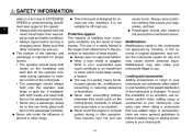
.... Loading and accessories Adding accessories or cargo to your legs, ankles, and feet. SAFETY INFORMATION wide on a turn due to EXCESSIVE SPEED or undercornering (insufficient lean angle for proper control. • The operator should keep both feet on the passenger footrests. • Never carry a passenger unless he or she can adversely affect stability and handling if the weight distribution of...
.... Loading and accessories Adding accessories or cargo to your legs, ankles, and feet. SAFETY INFORMATION wide on a turn due to EXCESSIVE SPEED or undercornering (insufficient lean angle for proper control. • The operator should keep both feet on the passenger footrests. • Never carry a passenger unless he or she can adversely affect stability and handling if the weight distribution of...
Owners Manual
Page 11
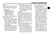
... improper weight distribution or aerodynamic changes. Use extreme caution when selecting and installing any way reduce ground clearance or cornering clearance, 1-3 G limit suspension travel, steering travel or control operation, or obscure lights or reflectors. • Accessories fitted to...passing or being passed by large vehicles. • Certain accessories can create instability due to the motorcycle as possible. G Shifting weights can create unstable handling or slow steering response. Accessories Genuine Yamaha accessories have been specifically designed for the proper selection, ...
... improper weight distribution or aerodynamic changes. Use extreme caution when selecting and installing any way reduce ground clearance or cornering clearance, 1-3 G limit suspension travel, steering travel or control operation, or obscure lights or reflectors. • Accessories fitted to...passing or being passed by large vehicles. • Certain accessories can create instability due to the motorcycle as possible. G Shifting weights can create unstable handling or slow steering response. Accessories Genuine Yamaha accessories have been specifically designed for the proper selection, ...
Owners Manual
Page 12
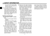
The exhaust fumes are poisonous and may limit control ability, therefore, such accessories are not likely to touch these hot areas. • Do not park the motorcycle on a slope or soft ground, otherwise it run for manual type). a kerosene heater, or near a flammable source (e.g. If it could cause a dangerous loss of time in an area that the fuel cock is turned to...
The exhaust fumes are poisonous and may limit control ability, therefore, such accessories are not likely to touch these hot areas. • Do not park the motorcycle on a slope or soft ground, otherwise it run for manual type). a kerosene heater, or near a flammable source (e.g. If it could cause a dangerous loss of time in an area that the fuel cock is turned to...
Owners Manual
Page 21
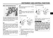
To lock the steering The main switch/steering lock controls the ignition and lighting systems, and is used to "OFF" or "LOCK". 1. Never turn it to "LOCK" while still pushing it . Turn. 1. Turn. EWA10060 WARNING ON All electrical circuits are off. Push. 2. NOTE: The headlight comes on automatically when the engine is stopped before turning the key to lock the steering. Remove the key. 3-1 Make sure that the vehicle is started . The key cannot be removed. Push...
To lock the steering The main switch/steering lock controls the ignition and lighting systems, and is used to "OFF" or "LOCK". 1. Never turn it to "LOCK" while still pushing it . Turn. 1. Turn. EWA10060 WARNING ON All electrical circuits are off. Push. 2. NOTE: The headlight comes on automatically when the engine is stopped before turning the key to lock the steering. Remove the key. 3-1 Make sure that the vehicle is started . The key cannot be removed. Push...
Owners Manual
Page 22
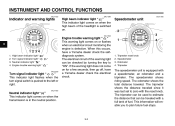
..., have a Yamaha dealer check the electrical circuit. 1. 2. 3. 4. EAU11060 Engine trouble warning light " " This warning light comes on . The electrical circuit of the warning light can be checked by turning the key to plan future fuel stops. 3-2 High beam indicator light " " Turn signal indicator light " Neutral indicator light " " Engine trouble warning light " " " EAU11020 Turn signal indicator light " " This indicator light flashes when the turn signal switch is switched on or flashes when an electrical circuit monitoring the engine is in the neutral position. This...
..., have a Yamaha dealer check the electrical circuit. 1. 2. 3. 4. EAU11060 Engine trouble warning light " " This warning light comes on . The electrical circuit of the warning light can be checked by turning the key to plan future fuel stops. 3-2 High beam indicator light " " Turn signal indicator light " Neutral indicator light " " Engine trouble warning light " " " EAU11020 Turn signal indicator light " " This indicator light flashes when the turn signal switch is switched on or flashes when an electrical circuit monitoring the engine is in the neutral position. This...
Owners Manual
Page 23
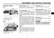
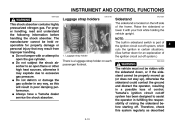
... throttle cable is moving, so that the turn signal lights can also be canceled manually by pushing the switch in after the vehicle has traveled both about 150 m (490 ft) and for the low beam. When released, the switch returns to starting the engine. Engine stop switch " / " Set this switch to " " before starting the engine. 1. Start switch " " / " 3-3 Engine stop switch " 2. INSTRUMENT AND CONTROL FUNCTIONS EAU12345 EAU12400 EAU12500 Handlebar switches Left Dimmer switch " / " Set this switch...
... throttle cable is moving, so that the turn signal lights can also be canceled manually by pushing the switch in after the vehicle has traveled both about 150 m (490 ft) and for the low beam. When released, the switch returns to starting the engine. Engine stop switch " / " Set this switch to " " before starting the engine. 1. Start switch " " / " 3-3 Engine stop switch " 2. INSTRUMENT AND CONTROL FUNCTIONS EAU12345 EAU12400 EAU12500 Handlebar switches Left Dimmer switch " / " Set this switch...
Owners Manual
Page 27
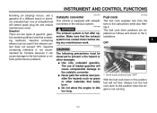
... to the catalytic converter. G Do not allow the engine to this position, fuel will not flow. INSTRUMENT AND CONTROL FUNCTIONS knocking (or pinging) occurs, use of unleaded fuel will cause unrepairable damage to the fuel system or vehicle performance problems. EAU13441 EAU13550 Catalytic converter This vehicle is equipped with catalytic converters in this position when the engine is hot after operation. Always turn the fuel cock lever to idle too long...
... to the catalytic converter. G Do not allow the engine to this position, fuel will not flow. INSTRUMENT AND CONTROL FUNCTIONS knocking (or pinging) occurs, use of unleaded fuel will cause unrepairable damage to the fuel system or vehicle performance problems. EAU13441 EAU13550 Catalytic converter This vehicle is equipped with catalytic converters in this position when the engine is hot after operation. Always turn the fuel cock lever to idle too long...
Owners Manual
Page 33
... the gas cylinder in fulfilling the responsibility of control. Raise the sidestand or lower it may result from improper handling. Yamaha's ignition circuit cut -off system has been designed to excessive gas pressure. G Always have a Yamaha dealer service the shock absorber....ignition circuit cut -off system.) EWA10240 3 1. INSTRUMENT AND CONTROL FUNCTIONS EWA10220 EAU15150 EAU15301 WARNING This shock absorber contains highly pressurized nitrogen gas. G Do not tamper with or attempt to an open the gas cylinder. G Do not subject the shock absorber to open flame or other high heat...
... the gas cylinder in fulfilling the responsibility of control. Raise the sidestand or lower it may result from improper handling. Yamaha's ignition circuit cut -off system has been designed to excessive gas pressure. G Always have a Yamaha dealer service the shock absorber....ignition circuit cut -off system.) EWA10240 3 1. INSTRUMENT AND CONTROL FUNCTIONS EWA10220 EAU15150 EAU15301 WARNING This shock absorber contains highly pressurized nitrogen gas. G Do not tamper with or attempt to an open the gas cylinder. G Do not subject the shock absorber to open flame or other high heat...
Owners Manual
Page 39
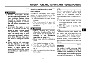
... WARNING G G Before starting , one attempt. NOTE: When the transmission is set to "ON" and make sure that the engine stop switch is in gear with the clutch lever pulled and the sidestand up . Always make sure that you do not thoroughly understand. Start the engine by pushing the start switch, wait a few seconds. Turn the fuel cock lever to start, release the start switch. Shift the transmission into the neutral...
... WARNING G G Before starting , one attempt. NOTE: When the transmission is set to "ON" and make sure that the engine stop switch is in gear with the clutch lever pulled and the sidestand up . Always make sure that you do not thoroughly understand. Start the engine by pushing the start switch, wait a few seconds. Turn the fuel cock lever to start, release the start switch. Shift the transmission into the neutral...
Owners Manual
Page 41
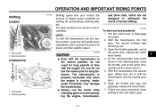
... of engine power available for starting off , and do not tow the motorcycle for long distances. At the recommended shift points shown in the illustration. Shift pedal 2. The transmission is properly lubricated only when the engine is running. and drive train, which are shown in the following table, close the throttle, and at the same time, release the clutch lever slowly. 4. The neutral indicator light should...
... of engine power available for starting off , and do not tow the motorcycle for long distances. At the recommended shift points shown in the illustration. Shift pedal 2. The transmission is properly lubricated only when the engine is running. and drive train, which are shown in the following table, close the throttle, and at the same time, release the clutch lever slowly. 4. The neutral indicator light should...
Owners Manual
Page 46
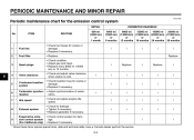
Replace. 6 4 * Valve clearance Crankcase breather system Carburetor synchronization Idle speed 5 * 6 * 7 * 8 * Exhaust system Evaporative emission control system (For California only) 9 * √ √ * Since these items require special tools, data and technical skills, have a Yamaha dealer perform the service. 6-3 PERIODIC MAINTENANCE AND MINOR REPAIR EAU17600 Periodic maintenance chart for damage. • Replace if necessary. √ √ 3 Spark plugs Replace. ITEM ROUTINE 600 mi (1000 km) or 1 month 4000 mi...
Replace. 6 4 * Valve clearance Crankcase breather system Carburetor synchronization Idle speed 5 * 6 * 7 * 8 * Exhaust system Evaporative emission control system (For California only) 9 * √ √ * Since these items require special tools, data and technical skills, have a Yamaha dealer perform the service. 6-3 PERIODIC MAINTENANCE AND MINOR REPAIR EAU17600 Periodic maintenance chart for damage. • Replace if necessary. √ √ 3 Spark plugs Replace. ITEM ROUTINE 600 mi (1000 km) or 1 month 4000 mi...
Owners Manual
Page 61
... rear): 1.0 mm (0.04 in it as soon as handling, braking, performance and safety. Securely pack your tires. Tire sidewall 2. Do not carry loosely packed items that the total weight of rider, passenger, cargo and accessories EWA10510 vehicle. if approved for this model) does not exceed the maximum load of an overloaded vehicle could cause tire damage, an accident, or even injury. PERIODIC MAINTENANCE AND MINOR REPAIR...
... rear): 1.0 mm (0.04 in it as soon as handling, braking, performance and safety. Securely pack your tires. Tire sidewall 2. Do not carry loosely packed items that the total weight of rider, passenger, cargo and accessories EWA10510 vehicle. if approved for this model) does not exceed the maximum load of an overloaded vehicle could cause tire damage, an accident, or even injury. PERIODIC MAINTENANCE AND MINOR REPAIR...
Owners Manual
Page 67
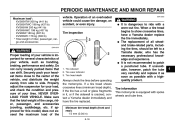
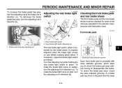
... make the brake light come on just before braking takes effect. To make the brake light come on earlier, turn the adjusting nut in direction (b). 6 1. Brake pad wear indicator groove Each front brake pad is properly adjusted when the brake light comes on later, turn the adjusting nut in direction (a). If a brake pad has worn to disassemble the brake. Rear brake light switch 2. Rear brake light switch adjusting nut 1. PERIODIC MAINTENANCE AND MINOR REPAIR To increase...
... make the brake light come on just before braking takes effect. To make the brake light come on earlier, turn the adjusting nut in direction (b). 6 1. Brake pad wear indicator groove Each front brake pad is properly adjusted when the brake light comes on later, turn the adjusting nut in direction (a). If a brake pad has worn to disassemble the brake. Rear brake light switch 2. Rear brake light switch adjusting nut 1. PERIODIC MAINTENANCE AND MINOR REPAIR To increase...
Owners Manual
Page 74
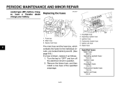
...behind panel B. (See page 6-8.) If a fuse is blown, replace it as follows. 1. EAU23524 Replacing the fuses 1. Turn the key to "OFF" and turn off the electrical circuit in question. 2. PERIODIC MAINTENANCE AND MINOR REPAIR sealed-type (MF) battery charger, have a Yamaha dealer charge your battery. Main fuse 3. Headlight fuse Signaling system fuse Ignition fuse Carburetor heater fuse Ignitor unit fuse Spare fuse Specified fuses: Main fuse: 30.0 A Signaling system fuse: 10.0 A Ignition fuse: 10.0 A Headlight fuse: 15.0 A Carburetor heater fuse: 15.0 A Ignitor unit fuse: 5.0 A 6-31 Fuse...
...behind panel B. (See page 6-8.) If a fuse is blown, replace it as follows. 1. EAU23524 Replacing the fuses 1. Turn the key to "OFF" and turn off the electrical circuit in question. 2. PERIODIC MAINTENANCE AND MINOR REPAIR sealed-type (MF) battery charger, have a Yamaha dealer charge your battery. Main fuse 3. Headlight fuse Signaling system fuse Ignition fuse Carburetor heater fuse Ignitor unit fuse Spare fuse Specified fuses: Main fuse: 30.0 A Signaling system fuse: 10.0 A Ignition fuse: 10.0 A Headlight fuse: 15.0 A Carburetor heater fuse: 15.0 A Ignitor unit fuse: 5.0 A 6-31 Fuse...
Owners Manual
Page 80
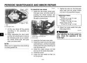
... rear wheel, wheel axle, final gear case, and drive shaft by pushing the wheel forward and guiding the drive shaft into the middle gear universal joint. 7. Middle gear universal joint 2. Bolt 2. Adjust the brake pedal free play adjusting nut onto the brake rod. 4. Install the brake rod onto the brake camshaft lever, and then install the brake pedal free play . (See page 6-23.) EWA10660 WARNING 1. Final gear case 6 7. Install the panel. 6. Lower the rear wheel...
... rear wheel, wheel axle, final gear case, and drive shaft by pushing the wheel forward and guiding the drive shaft into the middle gear universal joint. 7. Middle gear universal joint 2. Bolt 2. Adjust the brake pedal free play adjusting nut onto the brake rod. 4. Install the brake rod onto the brake camshaft lever, and then install the brake pedal free play . (See page 6-23.) EWA10660 WARNING 1. Final gear case 6 7. Install the panel. 6. Lower the rear wheel...
Owners Manual
Page 83
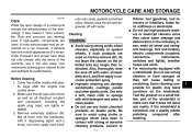
..., but it more vulnerable. A rusty exhaust pipe may leave scratches on spoked wheels. Remove extremely stubborn dirt, like oil burnt onto the crankcase, with the terms of wheel and swingarm bearings, fork and brakes), electric components (couplers, connectors, instruments, switches and lights), breather hoses and vents. For motorcycles equipped with a windshield: Do not use a quality plastic polishing compound after the engine has cooled down. 2.
..., but it more vulnerable. A rusty exhaust pipe may leave scratches on spoked wheels. Remove extremely stubborn dirt, like oil burnt onto the crankcase, with the terms of wheel and swingarm bearings, fork and brakes), electric components (couplers, connectors, instruments, switches and lights), breather hoses and vents. For motorcycles equipped with a windshield: Do not use a quality plastic polishing compound after the engine has cooled down. 2.
Owners Manual
Page 90
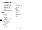
...1 Engine trouble warning light: 12 V, 1.7 W × 1 Fuses: Main fuse: 30.0 A Headlight fuse: 15.0 A Signaling system fuse: 10.0 A Ignition fuse: 10.0 A Carburetor heater fuse: 15.0 A Ignitor unit fuse: 5.0 A Electrical system: Ignition system: Transistorized coil ignition (digital) Charging system: AC magneto Battery: Model: GT12B-4 Voltage, capacity: 12 V, 10.0 Ah Headlight: Bulb type: Halogen bulb Bulb voltage, wattage × quantity: 8 Headlight: 12 V, 60 W/55.0 W × 1 Tail/brake light: 12 V, 8.0 W/27.0 W × 1 Front turn signal/position light: 12 V, 23 W/8.0 W × 2 Rear...
...1 Engine trouble warning light: 12 V, 1.7 W × 1 Fuses: Main fuse: 30.0 A Headlight fuse: 15.0 A Signaling system fuse: 10.0 A Ignition fuse: 10.0 A Carburetor heater fuse: 15.0 A Ignitor unit fuse: 5.0 A Electrical system: Ignition system: Transistorized coil ignition (digital) Charging system: AC magneto Battery: Model: GT12B-4 Voltage, capacity: 12 V, 10.0 Ah Headlight: Bulb type: Halogen bulb Bulb voltage, wattage × quantity: 8 Headlight: 12 V, 60 W/55.0 W × 1 Tail/brake light: 12 V, 8.0 W/27.0 W × 1 Front turn signal/position light: 12 V, 23 W/8.0 W × 2 Rear...
Owners Manual
Page 101
...Main switch/steering lock ...3-1 Maintenance and lubrication, periodic...6-4 Maintenance, emission control system ...6-3 Maintenance, periodic ...6-1 Maintenance record ...9-5 Model label...9-2 D Dimmer switch ...3-3 E Engine break-in ...5-4 Engine oil and oil filter element...6-11 Engine, starting a warm...5-2 Engine stop switch...3-3 Engine trouble warning light ...3-2 T Throttle cable free play, checking ...6-16 Throttle grip and cable, checking and lubricating ...6-27 Tires...6-17 Tool kit ...6-1 Troubleshooting ...6-38 N Neutral indicator light ...3-2 Noise regulation ...9-4 P Panels...
...Main switch/steering lock ...3-1 Maintenance and lubrication, periodic...6-4 Maintenance, emission control system ...6-3 Maintenance, periodic ...6-1 Maintenance record ...9-5 Model label...9-2 D Dimmer switch ...3-3 E Engine break-in ...5-4 Engine oil and oil filter element...6-11 Engine, starting a warm...5-2 Engine stop switch...3-3 Engine trouble warning light ...3-2 T Throttle cable free play, checking ...6-16 Throttle grip and cable, checking and lubricating ...6-27 Tires...6-17 Tool kit ...6-1 Troubleshooting ...6-38 N Neutral indicator light ...3-2 Noise regulation ...9-4 P Panels...