
Owners Manual
Page 7
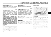
... INSTRUMENT AND CONTROL FUNCTIONS ...3-1 Main switch/steering lock ...3-1 Indicator and warning lights ...3-2 Speedometer unit ...3-3 Handlebar switches ...3-3 Clutch lever ...3-4 Shift pedal (XVS11W) ...3-5 Shift pedal (XVS11AWW/XVS11ATW) ...3-5 Brake lever ...3-5 Brake pedal ...3-6 Fuel tank cap ...3-6 Fuel ...3-7 Catalytic converter...3-8 Fuel cock ...3-8 Starter (choke) lever ...3-9 Seats (XVS11W) ...3-9 Seats (XVS11AWW/XVS11ATW) ...3-11 Helmet holder ...3-12 Storage compartment ...3-13 Adjusting the shock absorber assembly ...3-14 Luggage strap holders ...3-16 Sidestand ...3-16 Ignition...
... INSTRUMENT AND CONTROL FUNCTIONS ...3-1 Main switch/steering lock ...3-1 Indicator and warning lights ...3-2 Speedometer unit ...3-3 Handlebar switches ...3-3 Clutch lever ...3-4 Shift pedal (XVS11W) ...3-5 Shift pedal (XVS11AWW/XVS11ATW) ...3-5 Brake lever ...3-5 Brake pedal ...3-6 Fuel tank cap ...3-6 Fuel ...3-7 Catalytic converter...3-8 Fuel cock ...3-8 Starter (choke) lever ...3-9 Seats (XVS11W) ...3-9 Seats (XVS11AWW/XVS11ATW) ...3-11 Helmet holder ...3-12 Storage compartment ...3-13 Adjusting the shock absorber assembly ...3-14 Luggage strap holders ...3-16 Sidestand ...3-16 Ignition...

Owners Manual
Page 8
...wheel bearings ...6-29 Battery ...6-30 Replacing the fuses ...6-31 Replacing the headlight bulb ...6-33 Replacing a turn signal light bulb or the tail/brake light bulb ...6-34 Supporting the motorcycle ...6-34 Troubleshooting ...6-35 Troubleshooting chart ...6-36 MOTORCYCLE CARE AND STORAGE ...7-1 Care ...7-1 Storage ...7-3 SPECIFICATIONS ...8-1 CONSUMER INFORMATION ...9-1 Identification numbers ...9-1 Reporting safety defects ...9-3 Motorcycle noise regulation ...9-4 Maintenance record ...9-5 YAMAHA MOTOR CORPORATION, U.S.A. STREET AND ENDURO MOTORCYCLE LIMITED WARRANTY ...9-7 YAMAHA EXTENDED...
...wheel bearings ...6-29 Battery ...6-30 Replacing the fuses ...6-31 Replacing the headlight bulb ...6-33 Replacing a turn signal light bulb or the tail/brake light bulb ...6-34 Supporting the motorcycle ...6-34 Troubleshooting ...6-35 Troubleshooting chart ...6-36 MOTORCYCLE CARE AND STORAGE ...7-1 Care ...7-1 Storage ...7-3 SPECIFICATIONS ...8-1 CONSUMER INFORMATION ...9-1 Identification numbers ...9-1 Reporting safety defects ...9-3 Motorcycle noise regulation ...9-4 Maintenance record ...9-5 YAMAHA MOTOR CORPORATION, U.S.A. STREET AND ENDURO MOTORCYCLE LIMITED WARRANTY ...9-7 YAMAHA EXTENDED...
Owners Manual
Page 11
... front fender. Keep the following in any way reduce ground clearance or cornering clearance, 1-3 G limit suspension travel, steering travel or control operation, or obscure lights or reflectors. • Accessories fitted to the handlebar or the front fork area can create a sudden imbalance. Wind may seriously affect the stability of the motorcycle due to aerodynamic effects. G Shifting weights can create...
... front fender. Keep the following in any way reduce ground clearance or cornering clearance, 1-3 G limit suspension travel, steering travel or control operation, or obscure lights or reflectors. • Accessories fitted to the handlebar or the front fork area can create a sudden imbalance. Wind may seriously affect the stability of the motorcycle due to aerodynamic effects. G Shifting weights can create...
Owners Manual
Page 12
... adding electrical accessories. If electrical accessories exceed the capacity of the motorcycle's electrical system, an electric failure could result, which could catch fire. Always operate your clothes. If any gasoline, inhale a lot of lights or engine power. When parking the motorcycle, note the following: • The engine and exhaust system may be hot, therefore, park the motorcycle in an area that the fuel cock is turned to...
... adding electrical accessories. If electrical accessories exceed the capacity of the motorcycle's electrical system, an electric failure could result, which could catch fire. Always operate your clothes. If any gasoline, inhale a lot of lights or engine power. When parking the motorcycle, note the following: • The engine and exhaust system may be hot, therefore, park the motorcycle in an area that the fuel cock is turned to...

Owners Manual
Page 20
... with power, and the headlight, meter lighting, taillight and position lights come on, and the engine can be removed. The key can be started. EWA10060 ON All electrical systems are off . Remove the key. To lock the steering To unlock the steering 3 1. EAU10510 Push the key in from the "OFF" position, and then turn it . EAU10660 1. Turn the handlebars all electrical systems are described below. INSTRUMENT AND CONTROL...
... with power, and the headlight, meter lighting, taillight and position lights come on, and the engine can be removed. The key can be started. EWA10060 ON All electrical systems are off . Remove the key. To lock the steering To unlock the steering 3 1. EAU10510 Push the key in from the "OFF" position, and then turn it . EAU10660 1. Turn the handlebars all electrical systems are described below. INSTRUMENT AND CONTROL...
Owners Manual
Page 21
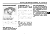
... when the turn signal switch is low. If the warning light does not come on for a few seconds, then go off , have a Yamaha dealer check the electrical circuit. When this is defective. The electrical circuit of the warning light can be checked by turning the key to "ON". The electrical circuit of the warning light can be checked by turning the key to "ON". INSTRUMENT AND CONTROL FUNCTIONS EAU11003...
... when the turn signal switch is low. If the warning light does not come on for a few seconds, then go off , have a Yamaha dealer check the electrical circuit. When this is defective. The electrical circuit of the warning light can be checked by turning the key to "ON". The electrical circuit of the warning light can be checked by turning the key to "ON". INSTRUMENT AND CONTROL FUNCTIONS EAU11003...
Owners Manual
Page 23
... system, the turn signal lights can also be pulled rapidly and released slowly for smooth clutch operation. INSTRUMENT AND CONTROL FUNCTIONS EAU12400 EAU12500 EAU12820 Dimmer switch " / " Set this switch to " " for the high beam and to the center position. NOTE: The self-canceling system only operates when the vehicle is located at an intersection. The lever should be canceled manually by pushing...
... system, the turn signal lights can also be pulled rapidly and released slowly for smooth clutch operation. INSTRUMENT AND CONTROL FUNCTIONS EAU12400 EAU12500 EAU12820 Dimmer switch " / " Set this switch to " " for the high beam and to the center position. NOTE: The self-canceling system only operates when the vehicle is located at an intersection. The lever should be canceled manually by pushing...

Owners Manual
Page 27
INSTRUMENT AND CONTROL FUNCTIONS EAU13441 EAU13550 Catalytic converter This vehicle is not running. 1. G Use only unleaded gasoline. Pointed end positioned over "OFF" With the fuel cock lever in this position when starting the engine and riding. G Never park the vehicle near possible fire hazards such as follows and shown in the exhaust system. Always turn the fuel cock lever to this position, fuel flows to prevent a fire hazard...
INSTRUMENT AND CONTROL FUNCTIONS EAU13441 EAU13550 Catalytic converter This vehicle is not running. 1. G Use only unleaded gasoline. Pointed end positioned over "OFF" With the fuel cock lever in this position when starting the engine and riding. G Never park the vehicle near possible fire hazards such as follows and shown in the exhaust system. Always turn the fuel cock lever to this position, fuel flows to prevent a fire hazard...

Owners Manual
Page 35
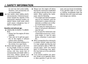
... each passenger footrest. NOTE: The built-in any way, as described 3-16 Do not deform or damage the gas cylinder in sidestand switch is a luggage strap holder on the left side of the frame. Raise the sidestand or lower it may explode due to assist the operator in poor damping performance. Always have a Yamaha dealer service the shock absorber...
... each passenger footrest. NOTE: The built-in any way, as described 3-16 Do not deform or damage the gas cylinder in sidestand switch is a luggage strap holder on the left side of the frame. Raise the sidestand or lower it may explode due to assist the operator in poor damping performance. Always have a Yamaha dealer service the shock absorber...
Owners Manual
Page 41
...: G The oil level warning light should come on when the key is adequate ventilation. If the sidestand is up . Do not crank the engine more than 10 seconds on after two to enable starting, one attempt. Turn the fuel cock lever to start, release the start switch. Shift the transmission into the neutral position. If the oil level warning light flickers or remains on any control or function...
...: G The oil level warning light should come on when the key is adequate ventilation. If the sidestand is up . Do not crank the engine more than 10 seconds on after two to enable starting, one attempt. Turn the fuel cock lever to start, release the start switch. Shift the transmission into the neutral position. If the oil level warning light flickers or remains on any control or function...
Owners Manual
Page 43
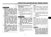
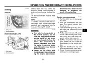
.... The transmission is properly lubricated only when the engine is running. EAU16680 1. Neutral position G Even with the transmission in the illustration. OPERATION AND IMPORTANT RIDING POINTS EAU16671 Shifting XVS11W Shifting gears lets you control the amount of forced shifting. The gear positions are not designed to withstand the shock of engine power available for long distances. Always use the clutch while changing gears to disengage the clutch. 2.
.... The transmission is properly lubricated only when the engine is running. EAU16680 1. Neutral position G Even with the transmission in the illustration. OPERATION AND IMPORTANT RIDING POINTS EAU16671 Shifting XVS11W Shifting gears lets you control the amount of forced shifting. The gear positions are not designed to withstand the shock of engine power available for long distances. Always use the clutch while changing gears to disengage the clutch. 2.
Owners Manual
Page 48
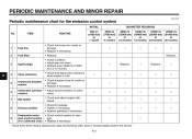
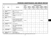
...; Check and adjust engine idle speed. • Check for leakage. • Tighten if necessary. • Replace gasket(s) if necessary. • Check control system for the emission control system INITIAL No. Replace. 6 4 * Valve clearance Crankcase breather system Carburetor synchronization Idle speed 5 * 6 * 7 * 8 * Exhaust system Evaporative emission control system (For California only) 9 * √ * Since these items require special tools, data and technical skills, have a Yamaha dealer perform the service. 6-3
...; Check and adjust engine idle speed. • Check for leakage. • Tighten if necessary. • Replace gasket(s) if necessary. • Check control system for the emission control system INITIAL No. Replace. 6 4 * Valve clearance Crankcase breather system Carburetor synchronization Idle speed 5 * 6 * 7 * 8 * Exhaust system Evaporative emission control system (For California only) 9 * √ * Since these items require special tools, data and technical skills, have a Yamaha dealer perform the service. 6-3
Owners Manual
Page 51
...; Apply Yamaha chain and cable lube or engine oil SAE 10W-30 thoroughly. • Check operation and free play. • Adjust the throttle cable free play if necessary. • Lubricate the throttle grip housing and cable. • Check operation. • Adjust headlight beam. √ 19 * 20 21 * 22 Final gear oil Change. √ √ √ Change. √ 6 23 * Front and rear brake switches Control cables...
...; Apply Yamaha chain and cable lube or engine oil SAE 10W-30 thoroughly. • Check operation and free play. • Adjust the throttle cable free play if necessary. • Lubricate the throttle grip housing and cable. • Check operation. • Adjust headlight beam. √ 19 * 20 21 * 22 Final gear oil Change. √ √ √ Change. √ 6 23 * Front and rear brake switches Control cables...
Owners Manual
Page 60
... tires. EWA10500 WARNING G 6 G The tire air pressure must be checked and, if necessary, adjusted before each ride. Tire air pressure (measured on cold tires (i.e., when the temperature of the tires equals the ambient temperature). PERIODIC MAINTENANCE AND MINOR REPAIR EAU21401 EAU32520 Valve clearance The valve clearance changes with the total weight of rider, passenger, cargo, and accessories approved for several characteristics of your vehicle, such as handling, braking, performance and safety. To prevent this model...
... tires. EWA10500 WARNING G 6 G The tire air pressure must be checked and, if necessary, adjusted before each ride. Tire air pressure (measured on cold tires (i.e., when the temperature of the tires equals the ambient temperature). PERIODIC MAINTENANCE AND MINOR REPAIR EAU21401 EAU32520 Valve clearance The valve clearance changes with the total weight of rider, passenger, cargo, and accessories approved for several characteristics of your vehicle, such as handling, braking, performance and safety. To prevent this model...

Owners Manual
Page 76
... shown by pushing the center in with a screwdriver, then pulling the fastener out. 1. 2. 3. 4. 5. 6. 7. 8. The fuse box, which contains the fuses for the main fuse. 1. Quick fastener 3. Remove the rider seat. (See page 3-9.) 2. Pull the ignitor unit panel outward to a sealed-type (MF) battery charger, have a Yamaha dealer charge your battery. Fuse box Headlight fuse Signaling system fuse Ignition fuse Carburetor heater fuse Ignitor unit fuse Backup fuse (for odometer) Spare...
... shown by pushing the center in with a screwdriver, then pulling the fastener out. 1. 2. 3. 4. 5. 6. 7. 8. The fuse box, which contains the fuses for the main fuse. 1. Quick fastener 3. Remove the rider seat. (See page 3-9.) 2. Pull the ignitor unit panel outward to a sealed-type (MF) battery charger, have a Yamaha dealer charge your battery. Fuse box Headlight fuse Signaling system fuse Ignition fuse Carburetor heater fuse Ignitor unit fuse Backup fuse (for odometer) Spare...

Owners Manual
Page 77
... position and install the quick fasteners. Main fuse 4. If the fuse immediately blows again, have a Yamaha dealer check the electrical system. 6 1. Install the rider seat. 6-32 PERIODIC MAINTENANCE AND MINOR REPAIR Specified fuses: Main fuse: 30.0 A Backup fuse: 5.0 A Ignition fuse: 10.0 A Headlight fuse: 15.0 A Carburetor heater fuse: 15.0 A Signaling system fuse: 10.0 A Ignitor unit fuse: 5.0 A ECA10640 8. Turn the key to "OFF" and turn on the electrical circuit in question. 5. CAUTION: Do not use...
... position and install the quick fasteners. Main fuse 4. If the fuse immediately blows again, have a Yamaha dealer check the electrical system. 6 1. Install the rider seat. 6-32 PERIODIC MAINTENANCE AND MINOR REPAIR Specified fuses: Main fuse: 30.0 A Backup fuse: 5.0 A Ignition fuse: 10.0 A Headlight fuse: 15.0 A Carburetor heater fuse: 15.0 A Signaling system fuse: 10.0 A Ignitor unit fuse: 5.0 A ECA10640 8. Turn the key to "OFF" and turn on the electrical circuit in question. 5. CAUTION: Do not use...

Owners Manual
Page 82
... it more vulnerable. A rusty exhaust pipe may leave scratches on plastic parts. ucts onto seals, gaskets and wheel axles. If the windshield is scratched, use high-pressure washers or steam-jet cleaners since they will also keep your motorcycle looking good, extend its life and optimize its performance. Rust and corrosion can damage windshields, cowlings, panels and other plastic parts...
... it more vulnerable. A rusty exhaust pipe may leave scratches on plastic parts. ucts onto seals, gaskets and wheel axles. If the windshield is scratched, use high-pressure washers or steam-jet cleaners since they will also keep your motorcycle looking good, extend its life and optimize its performance. Rust and corrosion can damage windshields, cowlings, panels and other plastic parts...

Owners Manual
Page 86
... lb) Engine: Engine type: Air cooled 4-stroke, SOHC Cylinder arrangement: V-type 2-cylinder Displacement: 1063.0 cm³ (64.86 cu.in) Bore × stroke: 95.0 × 75.0 mm (3.74 × 2.95 in) Compression ratio: 8.30 :1 8 Recommended engine oil grade: API service SE, SF, SG type or higher Engine oil quantity: Without oil filter element replacement: 3.00 L (3.17 US qt) (2.64 Imp.qt) With oil filter element replacement: 3.10...
... lb) Engine: Engine type: Air cooled 4-stroke, SOHC Cylinder arrangement: V-type 2-cylinder Displacement: 1063.0 cm³ (64.86 cu.in) Bore × stroke: 95.0 × 75.0 mm (3.74 × 2.95 in) Compression ratio: 8.30 :1 8 Recommended engine oil grade: API service SE, SF, SG type or higher Engine oil quantity: Without oil filter element replacement: 3.00 L (3.17 US qt) (2.64 Imp.qt) With oil filter element replacement: 3.10...

Owners Manual
Page 89
...1 Oil level warning light: 12 V, 1.7 W × 1 Turn signal indicator light: 12 V, 1.7 W × 1 Engine trouble warning light: 12 V, 1.7 W × 1 Signaling system fuse: 10.0 A Ignition fuse: 10.0 A Carburetor heater fuse: 15.0 A Ignitor unit fuse: 5.0 A Backup fuse: 5.0 A Front suspension: Type: Telescopic fork Spring/shock absorber type: Coil spring/oil damper Wheel travel: 140.0 mm (5.51 in) Rear suspension: Type: Swingarm (link suspension) Spring/shock absorber type: Coil spring/gas-oil damper Wheel travel: 113.0 mm (4.45 in) 8 Electrical system: Ignition system: Transistorized coil...
...1 Oil level warning light: 12 V, 1.7 W × 1 Turn signal indicator light: 12 V, 1.7 W × 1 Engine trouble warning light: 12 V, 1.7 W × 1 Signaling system fuse: 10.0 A Ignition fuse: 10.0 A Carburetor heater fuse: 15.0 A Ignitor unit fuse: 5.0 A Backup fuse: 5.0 A Front suspension: Type: Telescopic fork Spring/shock absorber type: Coil spring/oil damper Wheel travel: 140.0 mm (5.51 in) Rear suspension: Type: Swingarm (link suspension) Spring/shock absorber type: Coil spring/gas-oil damper Wheel travel: 113.0 mm (4.45 in) 8 Electrical system: Ignition system: Transistorized coil...

Owners Manual
Page 100
... Clutch lever free play, adjusting...6-21 K Key identification number ...9-1 L Labels, location of...1-5 Luggage strap holders...3-16 M Main switch/steering lock...3-1 Maintenance and lubrication, periodic...6-4 Maintenance, emission control system...6-3 Maintenance, periodic ...6-1 Maintenance record...9-5 Model label ...9-2 D Dimmer switch ...3-4 E Engine break-in...5-4 Engine oil ...6-10 Engine, starting a warm ...5-2 Engine stop switch ...3-4 Engine trouble warning light...3-2 N Neutral indicator light...3-2 Noise regulation...9-4 F Final gear oil ...6-12 Front and rear brake pads...
... Clutch lever free play, adjusting...6-21 K Key identification number ...9-1 L Labels, location of...1-5 Luggage strap holders...3-16 M Main switch/steering lock...3-1 Maintenance and lubrication, periodic...6-4 Maintenance, emission control system...6-3 Maintenance, periodic ...6-1 Maintenance record...9-5 Model label ...9-2 D Dimmer switch ...3-4 E Engine break-in...5-4 Engine oil ...6-10 Engine, starting a warm ...5-2 Engine stop switch ...3-4 Engine trouble warning light...3-2 N Neutral indicator light...3-2 Noise regulation...9-4 F Final gear oil ...6-12 Front and rear brake pads...