
Owners Manual
Page 7
......5-4 Parking ...5-5 PERIODIC MAINTENANCE AND MINOR REPAIR ...6-1 PERIODIC MAINTENANCE ...6-1 Owner's tool kit ...6-1 Periodic maintenance chart for the emission control system ...6-3 General maintenance and lubrication chart ...6-4 Removing and installing panels ...6-8 Checking the spark plugs ...6-9 Canister (for California only) ...6-10 Engine oil and oil filter element ...6-11 Final gear oil ...6-13 Cleaning the air filter element ...6-14 Carburetors ...6-16 Checking the throttle cable free play ...6-16 Valve clearance ...6-16 Tires ...6-17 Spoke wheels ...6-20 Accessories and replacement...
......5-4 Parking ...5-5 PERIODIC MAINTENANCE AND MINOR REPAIR ...6-1 PERIODIC MAINTENANCE ...6-1 Owner's tool kit ...6-1 Periodic maintenance chart for the emission control system ...6-3 General maintenance and lubrication chart ...6-4 Removing and installing panels ...6-8 Checking the spark plugs ...6-9 Canister (for California only) ...6-10 Engine oil and oil filter element ...6-11 Final gear oil ...6-13 Cleaning the air filter element ...6-14 Carburetors ...6-16 Checking the throttle cable free play ...6-16 Valve clearance ...6-16 Tires ...6-17 Spoke wheels ...6-20 Accessories and replacement...

Owners Manual
Page 8
... the steering ...6-29 Checking the wheel bearings ...6-29 Battery ...6-30 Replacing the fuses ...6-31 Replacing the headlight bulb ...6-32 Replacing a turn signal light bulb or the tail/brake light bulb ...6-33 Supporting the motorcycle ...6-34 Front wheel ...6-35 Rear wheel ...6-36 Troubleshooting ...6-38 Troubleshooting chart ...6-39 MOTORCYCLE CARE AND STORAGE ...7-1 Care ...7-1 Storage ...7-3 SPECIFICATIONS ...8-1 CONSUMER INFORMATION ...9-1 Identification numbers ...9-1 Reporting safety defects ...9-3 Motorcycle noise regulation ...9-4 Maintenance record ...9-5 YAMAHA MOTOR CORPORATION...
... the steering ...6-29 Checking the wheel bearings ...6-29 Battery ...6-30 Replacing the fuses ...6-31 Replacing the headlight bulb ...6-32 Replacing a turn signal light bulb or the tail/brake light bulb ...6-33 Supporting the motorcycle ...6-34 Front wheel ...6-35 Rear wheel ...6-36 Troubleshooting ...6-38 Troubleshooting chart ...6-39 MOTORCYCLE CARE AND STORAGE ...7-1 Care ...7-1 Storage ...7-3 SPECIFICATIONS ...8-1 CONSUMER INFORMATION ...9-1 Identification numbers ...9-1 Reporting safety defects ...9-3 Motorcycle noise regulation ...9-4 Maintenance record ...9-5 YAMAHA MOTOR CORPORATION...
Owners Manual
Page 10
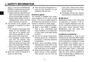
... to this motorcycle not approved by road and traffic conditions. • Always signal before turning or changing lanes. G 1 G G Protective apparel The majority of fatalities from motorcycle accidents are some general guidelines to follow if loading cargo or adding accessories to your motorcycle: 1-2 Passengers should always hold onto the operator, seat strap, or grab bar, if equipped, with both hands...
... to this motorcycle not approved by road and traffic conditions. • Always signal before turning or changing lanes. G 1 G G Protective apparel The majority of fatalities from motorcycle accidents are some general guidelines to follow if loading cargo or adding accessories to your motorcycle: 1-2 Passengers should always hold onto the operator, seat strap, or grab bar, if equipped, with both hands...
Owners Manual
Page 11
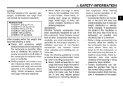
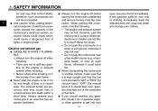
..., 1-3 G limit suspension travel, steering travel or control operation, or obscure lights or reflectors. • Accessories fitted to the handlebar or the front fork area can create unstable handling or slow steering response. Carefully inspect the accessory before riding. This improper position limits the freedom of movement of your motorcycle. SAFETY INFORMATION Loading The total weight of the operator, passenger, accessories and cargo...
..., 1-3 G limit suspension travel, steering travel or control operation, or obscure lights or reflectors. • Accessories fitted to the handlebar or the front fork area can create unstable handling or slow steering response. Carefully inspect the accessory before riding. This improper position limits the freedom of movement of your motorcycle. SAFETY INFORMATION Loading The total weight of the operator, passenger, accessories and cargo...
Owners Manual
Page 12
... may leak out of the carburetor or fuel tank. If it run for manual type). a kerosene heater, or near a flammable source (e.g. If any length of time in a place where pedestrians or children are poisonous and may limit control ability, therefore, such accessories are not recommended. G G Always turn the engine off before leaving the motorcycle unattended and remove the key from the main switch. SAFETY INFORMATION...
... may leak out of the carburetor or fuel tank. If it run for manual type). a kerosene heater, or near a flammable source (e.g. If any length of time in a place where pedestrians or children are poisonous and may limit control ability, therefore, such accessories are not recommended. G G Always turn the engine off before leaving the motorcycle unattended and remove the key from the main switch. SAFETY INFORMATION...

Owners Manual
Page 21
... steering The main switch/steering lock controls the ignition and lighting systems, and is stopped before turning the key to lock the steering. Turn. Turn the handlebars all electrical systems are off. EAU10580 3 1. NOTE: The headlight comes on until the key is started . Make sure that the vehicle is used to "OFF" or "LOCK". 1. Push the key in from the "OFF" position, and then turn it to "OFF", even if the engine...
... steering The main switch/steering lock controls the ignition and lighting systems, and is stopped before turning the key to lock the steering. Turn. Turn the handlebars all electrical systems are off. EAU10580 3 1. NOTE: The headlight comes on until the key is started . Make sure that the vehicle is used to "OFF" or "LOCK". 1. Push the key in from the "OFF" position, and then turn it to "OFF", even if the engine...

Owners Manual
Page 22
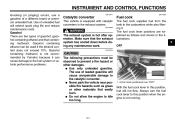
... turn signal switch is in the neutral position. EAU11060 Engine trouble warning light " " This warning light comes on for a few seconds, then go off, have a Yamaha dealer check the selfdiagnosis system. Tripmeter reset knob Speedometer Odometer Tripmeter Neutral indicator light " " This indicator light comes on . The tripmeter shows the distance traveled since it was last set to "ON". The electrical circuit of the headlight is switched...
... turn signal switch is in the neutral position. EAU11060 Engine trouble warning light " " This warning light comes on for a few seconds, then go off, have a Yamaha dealer check the selfdiagnosis system. Tripmeter reset knob Speedometer Odometer Tripmeter Neutral indicator light " " This indicator light comes on . The tripmeter shows the distance traveled since it was last set to "ON". The electrical circuit of the headlight is switched...
Owners Manual
Page 23
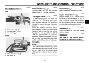
... center position. Since this switch to sound the horn. Turn signal switch " / " 3. EAU12430 Horn switch " " Press this model is equipped with the starter. Dimmer switch " / " 2. INSTRUMENT AND CONTROL FUNCTIONS EAU12343 EAU12400 EAU12500 Handlebar switches Left Dimmer switch " / " Set this switch to " " to stop the engine in after the vehicle has traveled both about 150 m (490 ft) and for the low beam. Set this switch to " " for starting instructions prior to starting...
... center position. Since this switch to sound the horn. Turn signal switch " / " 3. EAU12430 Horn switch " " Press this model is equipped with the starter. Dimmer switch " / " 2. INSTRUMENT AND CONTROL FUNCTIONS EAU12343 EAU12400 EAU12500 Handlebar switches Left Dimmer switch " / " Set this switch to " " to stop the engine in after the vehicle has traveled both about 150 m (490 ft) and for the low beam. Set this switch to " " for starting instructions prior to starting...
Owners Manual
Page 27
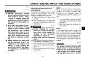
... that the exhaust system has cooled down before doing any maintenance work. G Never park the vehicle near possible fire hazards such as follows and shown in this position when the engine is equipped with catalytic converters in the exhaust system. Arrow mark positioned over "OFF" With the fuel cock lever in the illustrations. 3 OFF WARNING The exhaust system is not recommended by Yamaha because it...
... that the exhaust system has cooled down before doing any maintenance work. G Never park the vehicle near possible fire hazards such as follows and shown in this position when the engine is equipped with catalytic converters in the exhaust system. Arrow mark positioned over "OFF" With the fuel cock lever in the illustrations. 3 OFF WARNING The exhaust system is not recommended by Yamaha because it...

Owners Manual
Page 33
... for an explanation of the frame. Raise the sidestand or lower it may result from improper handling. Luggage strap holder There is a luggage strap holder on the left side of the ignition circuit cut -off system has been designed to an open the gas cylinder. INSTRUMENT AND CONTROL FUNCTIONS EWA10220 EAU15150 EAU15301 WARNING This shock absorber contains highly pressurized nitrogen gas.
... for an explanation of the frame. Raise the sidestand or lower it may result from improper handling. Luggage strap holder There is a luggage strap holder on the left side of the ignition circuit cut -off system has been designed to an open the gas cylinder. INSTRUMENT AND CONTROL FUNCTIONS EWA10220 EAU15150 EAU15301 WARNING This shock absorber contains highly pressurized nitrogen gas.

Owners Manual
Page 38
... tread depth. Correct if necessary. PAGE Wheels and tires 6-17, 6-20 Brake and shift pedals Brake and clutch levers Sidestand • Make sure that operation is smooth. • Lubricate pedal pivoting points ...bolts and screws are properly tightened. • Tighten if necessary. • Check operation. • Correct if necessary. • Check operation of ignition circuit cut-off system. • If system is defective, have Yamaha dealer check vehicle. 6-27 6-27 6-28 - - 3-13 4 Chassis fasteners Instruments, lights, signals and switches Sidestand switch 4-3 Check air pressure...
... tread depth. Correct if necessary. PAGE Wheels and tires 6-17, 6-20 Brake and shift pedals Brake and clutch levers Sidestand • Make sure that operation is smooth. • Lubricate pedal pivoting points ...bolts and screws are properly tightened. • Tighten if necessary. • Check operation. • Correct if necessary. • Check operation of ignition circuit cut-off system. • If system is defective, have Yamaha dealer check vehicle. 6-27 6-27 6-28 - - 3-13 4 Chassis fasteners Instruments, lights, signals and switches Sidestand switch 4-3 Check air pressure...
Owners Manual
Page 39
...: G The transmission is in a possible loss of consciousness and death within a short time. ECA11370 WARNING G G Before starting the engine, check the function of the ignition circuit cut -off system to preserve the battery. CAUTION: The engine trouble warning light should come on when the key is set to the procedure described on any control or function that the engine stop switch is turned to "ON...
...: G The transmission is in a possible loss of consciousness and death within a short time. ECA11370 WARNING G G Before starting the engine, check the function of the ignition circuit cut -off system to preserve the battery. CAUTION: The engine trouble warning light should come on when the key is set to the procedure described on any control or function that the engine stop switch is turned to "ON...
Owners Manual
Page 41
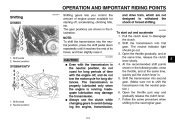
... the transmission. Pull the clutch lever to avoid damaging the engine, transmission, To start out and accelerate 1. At the recommended shift points shown in the following table, close the throttle, and at the same time, release the clutch lever slowly. 4. The gear positions are not designed to the next higher gear. 5 5-3 Shift pedal 2. Always use the clutch while changing gears to disengage the clutch. 2. The neutral indicator light should...
... the transmission. Pull the clutch lever to avoid damaging the engine, transmission, To start out and accelerate 1. At the recommended shift points shown in the following table, close the throttle, and at the same time, release the clutch lever slowly. 4. The gear positions are not designed to the next higher gear. 5 5-3 Shift pedal 2. Always use the clutch while changing gears to disengage the clutch. 2. The neutral indicator light should...
Owners Manual
Page 46
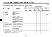
.... • Check control system for the emission control system INITIAL No. Replace. 6 4 * Valve clearance Crankcase breather system Carburetor synchronization Idle speed 5 * 6 * 7 * 8 * Exhaust system Evaporative emission control system (For California only) 9 * √ √ * Since these items require special tools, data and technical skills, have a Yamaha dealer perform the service. 6-3 PERIODIC MAINTENANCE AND MINOR REPAIR EAU17600 Periodic maintenance chart for damage. • Replace if necessary. √ √ 3 Spark plugs Replace.
.... • Check control system for the emission control system INITIAL No. Replace. 6 4 * Valve clearance Crankcase breather system Carburetor synchronization Idle speed 5 * 6 * 7 * 8 * Exhaust system Evaporative emission control system (For California only) 9 * √ √ * Since these items require special tools, data and technical skills, have a Yamaha dealer perform the service. 6-3 PERIODIC MAINTENANCE AND MINOR REPAIR EAU17600 Periodic maintenance chart for damage. • Replace if necessary. √ √ 3 Spark plugs Replace.

Owners Manual
Page 61
... condition and pressure of your tires. The replacement of the vehicle, and distribute the weight evenly from side to a Yamaha dealer, who has the necessary professional knowledge and experience. Properly adjust the suspension for several characteristics of your vehicle, such as possible with spoke wheels and tube tires. Tire wear indicator 3. Securely pack your heaviest items close to the center of all wheeland brake...
... condition and pressure of your tires. The replacement of the vehicle, and distribute the weight evenly from side to a Yamaha dealer, who has the necessary professional knowledge and experience. Properly adjust the suspension for several characteristics of your vehicle, such as possible with spoke wheels and tube tires. Tire wear indicator 3. Securely pack your heaviest items close to the center of all wheeland brake...

Owners Manual
Page 74
...blown fuse, and then install a new fuse of the specified amperage. 1. 2. 3. 4. 5. 6. EAU23524 Replacing the fuses 1. Headlight fuse Signaling system fuse Ignition fuse Carburetor heater fuse Ignitor unit fuse Spare fuse Specified fuses: Main fuse: 30.0 A Signaling system fuse: 10.0 A Ignition fuse: 10.0 A Headlight fuse: 15.0 A Carburetor heater fuse: 15.0 A Ignitor unit fuse: 5.0 A 6-31 Fuse box 2. Turn the key to "OFF" and turn off the electrical circuit in question. 2. Main fuse 3. PERIODIC MAINTENANCE AND MINOR REPAIR sealed-type (MF) battery charger, have a Yamaha dealer...
...blown fuse, and then install a new fuse of the specified amperage. 1. 2. 3. 4. 5. 6. EAU23524 Replacing the fuses 1. Headlight fuse Signaling system fuse Ignition fuse Carburetor heater fuse Ignitor unit fuse Spare fuse Specified fuses: Main fuse: 30.0 A Signaling system fuse: 10.0 A Ignition fuse: 10.0 A Headlight fuse: 15.0 A Carburetor heater fuse: 15.0 A Ignitor unit fuse: 5.0 A 6-31 Fuse box 2. Turn the key to "OFF" and turn off the electrical circuit in question. 2. Main fuse 3. PERIODIC MAINTENANCE AND MINOR REPAIR sealed-type (MF) battery charger, have a Yamaha dealer...

Owners Manual
Page 80
... the brake shoe plate. 5. Install the rear wheel, wheel axle, final gear case, and drive shaft by pushing the wheel forward and guiding the drive shaft into the middle gear universal joint. 7. Adjust the brake pedal free play , check the operation of the brake light. 2. Drive shaft After adjusting the brake pedal free play . (See page 6-23.) EWA10660 WARNING 1. Tighten the axle nut, the final gear case bolts and the brake torque...
... the brake shoe plate. 5. Install the rear wheel, wheel axle, final gear case, and drive shaft by pushing the wheel forward and guiding the drive shaft into the middle gear universal joint. 7. Adjust the brake pedal free play , check the operation of the brake light. 2. Drive shaft After adjusting the brake pedal free play . (See page 6-23.) EWA10660 WARNING 1. Tighten the axle nut, the final gear case bolts and the brake torque...

Owners Manual
Page 83
... on spoked wheels. Before cleaning 1. Cover the muffler outlets with a windshield: Do not use a quality plastic polishing compound after the engine has cooled down. 2. Remove extremely stubborn dirt, like oil burnt onto the crankcase, with water. Always rinse the dirt and degreaser off with the terms of wheel and swingarm bearings, fork and brakes), electric components (couplers, connectors, instruments, switches and lights), breather hoses and vents...
... on spoked wheels. Before cleaning 1. Cover the muffler outlets with a windshield: Do not use a quality plastic polishing compound after the engine has cooled down. 2. Remove extremely stubborn dirt, like oil burnt onto the crankcase, with water. Always rinse the dirt and degreaser off with the terms of wheel and swingarm bearings, fork and brakes), electric components (couplers, connectors, instruments, switches and lights), breather hoses and vents...

Owners Manual
Page 90
...mm (5.51 in) Bulb voltage, wattage × quantity: Headlight: 12 V, 60 W/55.0 W × 1 Tail/brake light: 12 V, 8.0 W/27.0 W × 1 Front turn signal/position light: 12 V, 23 W/8.0 W × 2 Rear turn signal light: 12 V, 21.0 W × 2 Meter lighting: 12 V, 1.7 W × 1 Neutral indicator light: 12 V, 1.7 W × 1 High beam indicator light: 12 V, 1.7 W × 1 Turn signal indicator light: 12 V, 1.7 W × 1 Engine trouble warning light: 12 V, 1.7 W × 1 Rear suspension: Type: Swingarm (monocross) Spring/shock absorber type: Coil spring/gas-oil damper Wheel travel: XVS65ATV 98...
...mm (5.51 in) Bulb voltage, wattage × quantity: Headlight: 12 V, 60 W/55.0 W × 1 Tail/brake light: 12 V, 8.0 W/27.0 W × 1 Front turn signal/position light: 12 V, 23 W/8.0 W × 2 Rear turn signal light: 12 V, 21.0 W × 2 Meter lighting: 12 V, 1.7 W × 1 Neutral indicator light: 12 V, 1.7 W × 1 High beam indicator light: 12 V, 1.7 W × 1 Turn signal indicator light: 12 V, 1.7 W × 1 Engine trouble warning light: 12 V, 1.7 W × 1 Rear suspension: Type: Swingarm (monocross) Spring/shock absorber type: Coil spring/gas-oil damper Wheel travel: XVS65ATV 98...
Owners Manual
Page 101
...Main switch/steering lock ...3-1 Maintenance and lubrication, periodic...6-4 Maintenance, emission control system ...6-3 Maintenance, periodic ...6-1 Maintenance record ...9-5 Model label...9-2 D Dimmer switch ...3-3 E Engine break-in ...5-4 Engine oil and oil filter element...6-11 Engine, starting a warm...5-2 Engine stop switch...3-3 Engine trouble warning light ...3-2 T Throttle cable free play, checking ...6-16 Throttle grip and cable, checking and lubricating ...6-27 Tires...6-17 Tool kit ...6-1 Troubleshooting ...6-38 N Neutral indicator light ...3-2 Noise regulation ...9-4 P Panels...
...Main switch/steering lock ...3-1 Maintenance and lubrication, periodic...6-4 Maintenance, emission control system ...6-3 Maintenance, periodic ...6-1 Maintenance record ...9-5 Model label...9-2 D Dimmer switch ...3-3 E Engine break-in ...5-4 Engine oil and oil filter element...6-11 Engine, starting a warm...5-2 Engine stop switch...3-3 Engine trouble warning light ...3-2 T Throttle cable free play, checking ...6-16 Throttle grip and cable, checking and lubricating ...6-27 Tires...6-17 Tool kit ...6-1 Troubleshooting ...6-38 N Neutral indicator light ...3-2 Noise regulation ...9-4 P Panels...