
Owners Manual
Page 7
... MINOR REPAIR ...6-1 PERIODIC MAINTENANCE ...6-1 Owner's tool kit ...6-1 Periodic maintenance chart for the emission control system ...6-3 General maintenance and lubrication chart ...6-4 Removing and installing panels ...6-8 Checking the spark plugs ...6-9 Canister (for California only) ...6-10 Engine oil and oil filter element ...6-11 Final gear oil ...6-13 Cleaning the air filter element ...6-14 Adjusting the carburetors ...6-16 Adjusting the throttle cable free play ...6-16 Adjusting the valve clearance ...6-16 Tires ...6-17 Spoke wheels ...6-19 Accessories and replacement...
... MINOR REPAIR ...6-1 PERIODIC MAINTENANCE ...6-1 Owner's tool kit ...6-1 Periodic maintenance chart for the emission control system ...6-3 General maintenance and lubrication chart ...6-4 Removing and installing panels ...6-8 Checking the spark plugs ...6-9 Canister (for California only) ...6-10 Engine oil and oil filter element ...6-11 Final gear oil ...6-13 Cleaning the air filter element ...6-14 Adjusting the carburetors ...6-16 Adjusting the throttle cable free play ...6-16 Adjusting the valve clearance ...6-16 Tires ...6-17 Spoke wheels ...6-19 Accessories and replacement...

Owners Manual
Page 8
... YAMAHA EXTENDED SERVICE (Y.E.S.) ...9-9 TABLE OF CONTENTS Checking the wheel bearings ...6-28 Battery ...6-29 Replacing the fuses ...6-30 Replacing the headlight bulb ...6-31 Replacing a turn signal light bulb or the tail/brake light bulb ...6-32 Supporting the motorcycle ...6-33 Front wheel ...6-34 Rear wheel ...6-35 Troubleshooting ...6-37 Troubleshooting chart ...6-38 MOTORCYCLE CARE AND STORAGE ...7-1 Care ...7-1 Storage ...7-3 SPECIFICATIONS ...8-1 CONSUMER INFORMATION ...9-1 Identification numbers ...9-1 Reporting safety defects ...9-3 Motorcycle noise regulation ...9-4 Maintenance...
... YAMAHA EXTENDED SERVICE (Y.E.S.) ...9-9 TABLE OF CONTENTS Checking the wheel bearings ...6-28 Battery ...6-29 Replacing the fuses ...6-30 Replacing the headlight bulb ...6-31 Replacing a turn signal light bulb or the tail/brake light bulb ...6-32 Supporting the motorcycle ...6-33 Front wheel ...6-34 Rear wheel ...6-35 Troubleshooting ...6-37 Troubleshooting chart ...6-38 MOTORCYCLE CARE AND STORAGE ...7-1 Care ...7-1 Storage ...7-3 SPECIFICATIONS ...8-1 CONSUMER INFORMATION ...9-1 Identification numbers ...9-1 Reporting safety defects ...9-3 Motorcycle noise regulation ...9-4 Maintenance...

Owners Manual
Page 10
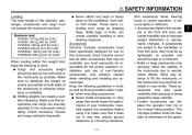
...turn due to EXCESSIVE SPEED or undercornering (insufficient lean angle for proper control. • The operator should keep both feet on the passenger footrests. Wind in your legs, ankles, and feet. The posture of vision which could catch on the control levers, footrests, or wheels and cause injury or an accident. G Never touch the engine or exhaust...or lacerations. Loading and accessories Adding accessories or cargo to your motorcycle illegal to this motorcycle not approved by road and traffic conditions. • Always signal before turning or changing lanes. G This ...
...turn due to EXCESSIVE SPEED or undercornering (insufficient lean angle for proper control. • The operator should keep both feet on the passenger footrests. Wind in your legs, ankles, and feet. The posture of vision which could catch on the control levers, footrests, or wheels and cause injury or an accident. G Never touch the engine or exhaust...or lacerations. Loading and accessories Adding accessories or cargo to your motorcycle illegal to this motorcycle not approved by road and traffic conditions. • Always signal before turning or changing lanes. G This ...
Owners Manual
Page 11
Make sure to distribute the weight as evenly as possible on this weight limit, keep the following guidelines in any way reduce ground clearance or cornering clearance, 1-3 G limit suspension travel, steering travel or control operation, or obscure lights or reflectors. • Accessories fitted to the handlebar or the front fork area can create unstable handling or slow steering response. Use extreme...
Make sure to distribute the weight as evenly as possible on this weight limit, keep the following guidelines in any way reduce ground clearance or cornering clearance, 1-3 G limit suspension travel, steering travel or control operation, or obscure lights or reflectors. • Accessories fitted to the handlebar or the front fork area can create unstable handling or slow steering response. Use extreme...
Owners Manual
Page 12
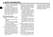
... any length of time in an area that it run for manual type). When transporting the motorcycle in the vicinity of an open flame), otherwise it may leak out of the carburetor or fuel tank. G G Always turn the engine off before leaving the motorcycle unattended and remove the key from the main switch. The exhaust fumes are poisonous and may limit control ability...
... any length of time in an area that it run for manual type). When transporting the motorcycle in the vicinity of an open flame), otherwise it may leak out of the carburetor or fuel tank. G G Always turn the engine off before leaving the motorcycle unattended and remove the key from the main switch. The exhaust fumes are poisonous and may limit control ability...
Owners Manual
Page 22
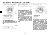
... by turning the key to zero with a full tank of the headlight is switched on for a few seconds, then go off, have a Yamaha dealer check the selfdiagnosis system. The tripmeter shows the distance traveled since it was last set to "ON". The speedometer shows riding speed. High beam indicator light " " Turn signal indicator light " Neutral indicator light " " Engine trouble warning light " " " EAU11020 Turn signal indicator light " " This indicator light...
... by turning the key to zero with a full tank of the headlight is switched on for a few seconds, then go off, have a Yamaha dealer check the selfdiagnosis system. The tripmeter shows the distance traveled since it was last set to "ON". The speedometer shows riding speed. High beam indicator light " " Turn signal indicator light " Neutral indicator light " " Engine trouble warning light " " " EAU11020 Turn signal indicator light " " This indicator light...
Owners Manual
Page 23
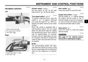
.... Engine stop switch " 2. Start switch " " / " 3-3 EAU12660 1. Since this model is stuck. Set this switch to " " to the center position. EAU12710 3 Start switch " " Push this switch to the center position. To signal a left-hand turn signal lights can also be canceled manually by pushing the switch in case of an emergency, such as when the vehicle overturns or when the throttle cable is equipped with the starter. However, the turn , push this switch...
.... Engine stop switch " 2. Start switch " " / " 3-3 EAU12660 1. Since this model is stuck. Set this switch to " " to the center position. EAU12710 3 Start switch " " Push this switch to the center position. To signal a left-hand turn signal lights can also be canceled manually by pushing the switch in case of an emergency, such as when the vehicle overturns or when the throttle cable is equipped with the starter. However, the turn , push this switch...
Owners Manual
Page 27
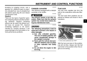
... when the engine is equipped with a catalytic converter in the illustrations. 3 OFF WARNING The exhaust system is hot after operation. INSTRUMENT AND CONTROL FUNCTIONS knocking (or pinging) occurs, use of gasohol: gasohol containing ethanol and that the exhaust system has cooled down before doing any maintenance work. Gasohol containing methanol is not recommended by Yamaha because it . G Never park the vehicle near possible fire hazards such...
... when the engine is equipped with a catalytic converter in the illustrations. 3 OFF WARNING The exhaust system is hot after operation. INSTRUMENT AND CONTROL FUNCTIONS knocking (or pinging) occurs, use of gasohol: gasohol containing ethanol and that the exhaust system has cooled down before doing any maintenance work. Gasohol containing methanol is not recommended by Yamaha because it . G Never park the vehicle near possible fire hazards such...

Owners Manual
Page 32
... gas cylinder. Remove the passenger and rider seats. (See page 3-9.) 3. To decrease the spring preload and thereby soften the suspension, turn an adjusting mechanism beyond the maximum or minimum settings. G Do not tamper with a spring preload adjusting ring. INSTRUMENT AND CONTROL FUNCTIONS EAU14860 Adjusting the shock absorber assembly 2. To increase the spring preload and thereby harden the suspension, turn the adjusting ring in poor damping performance...
... gas cylinder. Remove the passenger and rider seats. (See page 3-9.) 3. To decrease the spring preload and thereby soften the suspension, turn an adjusting mechanism beyond the maximum or minimum settings. G Do not tamper with a spring preload adjusting ring. INSTRUMENT AND CONTROL FUNCTIONS EAU14860 Adjusting the shock absorber assembly 2. To increase the spring preload and thereby harden the suspension, turn the adjusting ring in poor damping performance...
Owners Manual
Page 39
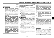
... 10 seconds on page 3-14. Turn the fuel cock lever to the procedure described on any one of time. CAUTION: The engine trouble warning light should be as short as possible to start, release the start switch, wait a few seconds. If the sidestand is turned to " ". 3. NOTE: If the engine fails to preserve the battery. Never start switch. NOTE: When the transmission is in a possible loss...
... 10 seconds on page 3-14. Turn the fuel cock lever to the procedure described on any one of time. CAUTION: The engine trouble warning light should be as short as possible to start, release the start switch, wait a few seconds. If the sidestand is turned to " ". 3. NOTE: If the engine fails to preserve the battery. Never start switch. NOTE: When the transmission is in a possible loss...

Owners Manual
Page 41
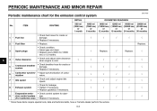
... the shock of forced shifting. Shift pedal 2. Always use the clutch while changing gears to shift the transmission into the neutral position.) 6. Neutral position ECA10260 CAUTION: G XVS650A/AT 1. Neutral position G Even with the engine off , accelerating, climbing hills, etc. The neutral indicator light should go out. 3. OPERATION AND IMPORTANT RIDING POINTS EAU16671 Shifting XVS650 Shifting gears lets you control the amount of engine power available for starting...
... the shock of forced shifting. Shift pedal 2. Always use the clutch while changing gears to shift the transmission into the neutral position.) 6. Neutral position ECA10260 CAUTION: G XVS650A/AT 1. Neutral position G Even with the engine off , accelerating, climbing hills, etc. The neutral indicator light should go out. 3. OPERATION AND IMPORTANT RIDING POINTS EAU16671 Shifting XVS650 Shifting gears lets you control the amount of engine power available for starting...
Owners Manual
Page 46
...; Replace gasket(s) if necessary. • Check control system for the emission control system INITIAL No. PERIODIC MAINTENANCE AND MINOR REPAIR EAU17600 Periodic maintenance chart for damage. • Replace if necessary. √ √ 3 Spark plugs Replace. Replace. 6 4 * Valve clearance Crankcase breather system Carburetor synchronization Idle speed 5 * 6 * 7 * 8 * Exhaust system Evaporative emission control system (For California only) 9 * √ √ * Since these items require special tools, data and technical skills, have a Yamaha...
...; Replace gasket(s) if necessary. • Check control system for the emission control system INITIAL No. PERIODIC MAINTENANCE AND MINOR REPAIR EAU17600 Periodic maintenance chart for damage. • Replace if necessary. √ √ 3 Spark plugs Replace. Replace. 6 4 * Valve clearance Crankcase breather system Carburetor synchronization Idle speed 5 * 6 * 7 * 8 * Exhaust system Evaporative emission control system (For California only) 9 * √ √ * Since these items require special tools, data and technical skills, have a Yamaha...

Owners Manual
Page 66
..., adjust the brake light switch as follows. 1. To make the brake light come on just before braking takes effect. Brake pedal position adjusting bolt 3. Tighten the locknut. EWA11230 WARNING 6 After adjusting the brake pedal position, the brake pedal free play adjusting nut 1. Rear brake light switch 2. Rear brake light switch adjusting nut The rear brake light switch, which is activated by the brake pedal, is properly adjusted when the brake light comes on earlier, turn the adjusting...
..., adjust the brake light switch as follows. 1. To make the brake light come on just before braking takes effect. Brake pedal position adjusting bolt 3. Tighten the locknut. EWA11230 WARNING 6 After adjusting the brake pedal position, the brake pedal free play adjusting nut 1. Rear brake light switch 2. Rear brake light switch adjusting nut The rear brake light switch, which is activated by the brake pedal, is properly adjusted when the brake light comes on earlier, turn the adjusting...

Owners Manual
Page 73
... turn off the electrical circuit in question. 2. Fuse box 2. EAU23524 Replacing the fuses 1. Headlight fuse Signaling system fuse Ignition fuse Carburetor heater fuse Ignitor unit fuse (for California only) Spare fuse Spare fuse (for the individual circuits, are located behind panel B. (See page 6-8.) If a fuse is blown, replace it as follows. 1. Main fuse 3. Remove the blown fuse, and then install a new fuse of the specified amperage. 1. 2. 3. 4. 5. 6. 7. PERIODIC MAINTENANCE AND MINOR REPAIR sealed-type (MF) battery...
... turn off the electrical circuit in question. 2. Fuse box 2. EAU23524 Replacing the fuses 1. Headlight fuse Signaling system fuse Ignition fuse Carburetor heater fuse Ignitor unit fuse (for California only) Spare fuse Spare fuse (for the individual circuits, are located behind panel B. (See page 6-8.) If a fuse is blown, replace it as follows. 1. Main fuse 3. Remove the blown fuse, and then install a new fuse of the specified amperage. 1. 2. 3. 4. 5. 6. 7. PERIODIC MAINTENANCE AND MINOR REPAIR sealed-type (MF) battery...

Owners Manual
Page 74
... a Yamaha dealer check the electrical system. 2. Disconnect the headlight coupler, and then remove the bulb cover. 1. Remove the headlight unit by removing the screws. 1. PERIODIC MAINTENANCE AND MINOR REPAIR EAU23792 Specified fuses: Main fuse: 30.0 A Signaling system fuse: 10.0 A Ignition fuse: 10.0 A Headlight fuse: 15.0 A Carburetor heater fuse: 15.0 A Ignitor unit fuse: XVS650 5.0 A (CAL) XVS650A 5.0 A (CAL) XVS650AT 5.0 A (CAL) ECA10640 Replacing the headlight bulb This model is equipped with a quartz bulb headlight. If the headlight bulb burns out, replace...
... a Yamaha dealer check the electrical system. 2. Disconnect the headlight coupler, and then remove the bulb cover. 1. Remove the headlight unit by removing the screws. 1. PERIODIC MAINTENANCE AND MINOR REPAIR EAU23792 Specified fuses: Main fuse: 30.0 A Signaling system fuse: 10.0 A Ignition fuse: 10.0 A Headlight fuse: 15.0 A Carburetor heater fuse: 15.0 A Ignitor unit fuse: XVS650 5.0 A (CAL) XVS650A 5.0 A (CAL) XVS650AT 5.0 A (CAL) ECA10640 Replacing the headlight bulb This model is equipped with a quartz bulb headlight. If the headlight bulb burns out, replace...

Owners Manual
Page 79
... the wheel forward and guiding the drive shaft into the middle gear universal joint. 7. Final gear case 7. Drive shaft After adjusting the brake pedal free play . (See page 6-22.) EWA10660 WARNING 1. Bolt 2. PERIODIC MAINTENANCE AND MINOR REPAIR EAU25511 To install the rear wheel 1. Tighten the axle nut, the final gear case bolts and the brake torque rod nuts to the procedure on the ground. 6-36 Lift the rear wheel off the ground according...
... the wheel forward and guiding the drive shaft into the middle gear universal joint. 7. Final gear case 7. Drive shaft After adjusting the brake pedal free play . (See page 6-22.) EWA10660 WARNING 1. Bolt 2. PERIODIC MAINTENANCE AND MINOR REPAIR EAU25511 To install the rear wheel 1. Tighten the axle nut, the final gear case bolts and the brake torque rod nuts to the procedure on the ground. 6-36 Lift the rear wheel off the ground according...

Owners Manual
Page 82
... following areas: seals (of wheel and swingarm bearings, fork and brakes), electric components (couplers, connectors, instruments, switches and lights), breather hoses and vents. Also, thoroughly rinse the area off with plastic bags after washing. Be sure to clean plastic. Rust and corrosion can damage windshields, cowlings, panels and other plastic parts. Before cleaning 1. Cover the muffler outlets with water. Some cleaning compounds for...
... following areas: seals (of wheel and swingarm bearings, fork and brakes), electric components (couplers, connectors, instruments, switches and lights), breather hoses and vents. Also, thoroughly rinse the area off with plastic bags after washing. Be sure to clean plastic. Rust and corrosion can damage windshields, cowlings, panels and other plastic parts. Before cleaning 1. Cover the muffler outlets with water. Some cleaning compounds for...

Owners Manual
Page 86
... in) Compression ratio: 9.00 :1 Starting system: Electric starter Lubrication system: Wet sump Final gear oil: Type: SAE80 API GL-4 Hypoid gear oil Quantity: 0.19 L (0.20 US qt) (0.17 Imp.qt) Air filter: Air filter element: Dry element Fuel: Recommended fuel: Unleaded gasoline only Fuel tank capacity: 16.0 L (4.23 US gal) (3.52 Imp.gal) Fuel reserve amount: 3.0 L (0.79 US gal) (0.66 Imp.gal) Engine oil: Type: YAMALUBE 4, SAE10W30 or SAE20W40...
... in) Compression ratio: 9.00 :1 Starting system: Electric starter Lubrication system: Wet sump Final gear oil: Type: SAE80 API GL-4 Hypoid gear oil Quantity: 0.19 L (0.20 US qt) (0.17 Imp.qt) Air filter: Air filter element: Dry element Fuel: Recommended fuel: Unleaded gasoline only Fuel tank capacity: 16.0 L (4.23 US gal) (3.52 Imp.gal) Fuel reserve amount: 3.0 L (0.79 US gal) (0.66 Imp.gal) Engine oil: Type: YAMALUBE 4, SAE10W30 or SAE20W40...

Owners Manual
Page 88
... light: 12 V, 1.7 W × 1 Turn signal indicator light: 12 V, 1.7 W × 1 Engine trouble warning light: 12 V, 1.7 W × 1 Fuses: Main fuse: 30.0 A Headlight fuse: 15.0 A Signaling system fuse: 10.0 A Ignition fuse: 10.0 A Carburetor heater fuse: 15.0 A Ignitor unit fuse: XVS650 5.0 A (CAL) XVS650A 5.0 A (CAL) XVS650AT 5.0 A (CAL) Front brake: Type: Single disc brake Operation: Right hand operation Recommended fluid: DOT 4 Battery: Model: GT12B-4 Voltage, capacity: 12 V, 10.0 Ah 8 Headlight: Bulb type: Halogen bulb Rear brake: Type: Drum brake Operation: Right foot operation Bulb...
... light: 12 V, 1.7 W × 1 Turn signal indicator light: 12 V, 1.7 W × 1 Engine trouble warning light: 12 V, 1.7 W × 1 Fuses: Main fuse: 30.0 A Headlight fuse: 15.0 A Signaling system fuse: 10.0 A Ignition fuse: 10.0 A Carburetor heater fuse: 15.0 A Ignitor unit fuse: XVS650 5.0 A (CAL) XVS650A 5.0 A (CAL) XVS650AT 5.0 A (CAL) Front brake: Type: Single disc brake Operation: Right hand operation Recommended fluid: DOT 4 Battery: Model: GT12B-4 Voltage, capacity: 12 V, 10.0 Ah 8 Headlight: Bulb type: Halogen bulb Rear brake: Type: Drum brake Operation: Right foot operation Bulb...
Owners Manual
Page 99
...Main switch/steering lock ...3-1 Maintenance and lubrication, periodic...6-4 Maintenance, emission control system ...6-3 Maintenance, periodic ...6-1 Maintenance record ...9-5 Model label...9-2 D Dimmer switch ...3-3 E Engine break-in ...5-4 Engine oil and oil filter element...6-11 Engine, starting a warm...5-2 Engine stop switch...3-3 Engine trouble warning light ...3-2 T Throttle cable free play, adjusting...6-16 Throttle grip and cable, checking and lubricating ...6-26 Tires...6-17 Tool kit ...6-1 Troubleshooting ...6-37 N Neutral indicator light ...3-2 Noise regulation ...9-4 P Panels...
...Main switch/steering lock ...3-1 Maintenance and lubrication, periodic...6-4 Maintenance, emission control system ...6-3 Maintenance, periodic ...6-1 Maintenance record ...9-5 Model label...9-2 D Dimmer switch ...3-3 E Engine break-in ...5-4 Engine oil and oil filter element...6-11 Engine, starting a warm...5-2 Engine stop switch...3-3 Engine trouble warning light ...3-2 T Throttle cable free play, adjusting...6-16 Throttle grip and cable, checking and lubricating ...6-26 Tires...6-17 Tool kit ...6-1 Troubleshooting ...6-37 N Neutral indicator light ...3-2 Noise regulation ...9-4 P Panels...