
Owners Manual
Page 6
... SPECIFICATION LABELS...1-1 SAFETY INFORMATION...2-1 DESCRIPTION AND MACHINE IDENTIFICATION ...3-1 Identification number records...3-2 Key identification number...3-2 Vehicle identification number ...3-3 Model label ...3-3 2 3 CONTROL FUNCTIONS...4-1 Main switch ...4-1 Indicator and warning lights ...4-2 Speedometer ...4-6 Fuel gauge ...4-6 Handlebar switches ...4-7 Throttle lever ...4-10 Speed limiter ...4-11 Front brake lever...4-12 Brake pedal and rear brake lever ...4-12 Drive select lever ...4-13 Recoil starter...4-13 Fuel tank cap ...4-14 Fuel cock...4-15 Starter (choke) ...4-16 Seat...
... SPECIFICATION LABELS...1-1 SAFETY INFORMATION...2-1 DESCRIPTION AND MACHINE IDENTIFICATION ...3-1 Identification number records...3-2 Key identification number...3-2 Vehicle identification number ...3-3 Model label ...3-3 2 3 CONTROL FUNCTIONS...4-1 Main switch ...4-1 Indicator and warning lights ...4-2 Speedometer ...4-6 Fuel gauge ...4-6 Handlebar switches ...4-7 Throttle lever ...4-10 Speed limiter ...4-11 Front brake lever...4-12 Brake pedal and rear brake lever ...4-12 Drive select lever ...4-13 Recoil starter...4-13 Fuel tank cap ...4-14 Fuel cock...4-15 Starter (choke) ...4-16 Seat...
Owners Manual
Page 7
5 PRE-OPERATION CHECKS ...5-1 Front and rear brakes ...5-2 Fuel ...5-4 Engine oil ...5-6 Final gear oil...5-6 Differential gear oil ...5-7 Coolant...5-8 Throttle lever ...5-9 Fittings and fasteners...5-9 Lights...5-9 Switches...5-9 Tires ...5-10 How to measure tire pressure...5-12 Tire wear limit...5-13 OPERATION...6-1 Starting a cold engine ...6-1 Starting a warm engine...6-3 Warming up...6-3 Drive select lever operation and reverse driving...6-4 Engine break-in...6-7 Parking ...6-8 Parking on a slope...6-9 Accessories and loading ...6-10 7 RIDING YOUR ATV ...7-1 Getting to know your ATV ...
5 PRE-OPERATION CHECKS ...5-1 Front and rear brakes ...5-2 Fuel ...5-4 Engine oil ...5-6 Final gear oil...5-6 Differential gear oil ...5-7 Coolant...5-8 Throttle lever ...5-9 Fittings and fasteners...5-9 Lights...5-9 Switches...5-9 Tires ...5-10 How to measure tire pressure...5-12 Tire wear limit...5-13 OPERATION...6-1 Starting a cold engine ...6-1 Starting a warm engine...6-3 Warming up...6-3 Drive select lever operation and reverse driving...6-4 Engine break-in...6-7 Parking ...6-8 Parking on a slope...6-9 Accessories and loading ...6-10 7 RIDING YOUR ATV ...7-1 Getting to know your ATV ...
Owners Manual
Page 8
...and tool kit...8-1 Periodic maintenance/ lubrication ...8-3 Panel removal and installation ...8-6 Engine oil and oil filter cartridge ...8-12 Final gear oil ...8-18 Differential gear oil replacement ...8-21 Cooling system...8-23 Changing the coolant ...8-24 Axle boots...8-28 Spark plug inspection...8-29 Air filter element cleaning...8-31 V-belt cooling duct check hose ...8-34 V-belt case drain plug...8-35 Spark arrester cleaning ...8-35 Carburetor adjustment...8-37 Idle speed adjustment ...8-37 Valve clearance adjustment ...8-38 Throttle lever adjustment...8-38 Select lever safety system cable...
...and tool kit...8-1 Periodic maintenance/ lubrication ...8-3 Panel removal and installation ...8-6 Engine oil and oil filter cartridge ...8-12 Final gear oil ...8-18 Differential gear oil replacement ...8-21 Cooling system...8-23 Changing the coolant ...8-24 Axle boots...8-28 Spark plug inspection...8-29 Air filter element cleaning...8-31 V-belt cooling duct check hose ...8-34 V-belt case drain plug...8-35 Spark arrester cleaning ...8-35 Carburetor adjustment...8-37 Idle speed adjustment ...8-37 Valve clearance adjustment ...8-38 Throttle lever adjustment...8-38 Select lever safety system cable...
Owners Manual
Page 20
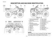
...compartment and tool kit 4. Fuel cock 11. Spark arrester 3. Air filter case 12. Rear shock absorber assembly spring preload adjusting ring 2. EBU00032 1- Spark plug 5. Rear brake fluid reservoir 6. Radiator cap 10. Front shock absorber assembly spring preload adjusting ring 7. Brake pedal 8. Engine oil dipstick Oil filter cartridge Coolant reservoir V-belt cooling duct check hose Rear brake lever Left handlebar switches Starter (choke) Drive select lever Speedometer Main switch Fuel tank cap Auxiliary DC jack Right handlebar switch Throttle lever Front brake lever NOTE...
...compartment and tool kit 4. Fuel cock 11. Spark arrester 3. Air filter case 12. Rear shock absorber assembly spring preload adjusting ring 2. EBU00032 1- Spark plug 5. Rear brake fluid reservoir 6. Radiator cap 10. Front shock absorber assembly spring preload adjusting ring 7. Brake pedal 8. Engine oil dipstick Oil filter cartridge Coolant reservoir V-belt cooling duct check hose Rear brake lever Left handlebar switches Starter (choke) Drive select lever Speedometer Main switch Fuel tank cap Auxiliary DC jack Right handlebar switch Throttle lever Front brake lever NOTE...
Owners Manual
Page 24
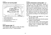
... hot. Push the start switch is in the "P" (park) position. If the warning light does not come on during operation, stop switch to " " and turn the key to cool down for about 10 minutes. Coolant temperature warning light " " When the coolant temperature reaches a specified level, this light comes on when the drive select lever is pushed, have a Yamaha dealer check the electrical circuit. 4-2 Shift the drive select lever into...
... hot. Push the start switch is in the "P" (park) position. If the warning light does not come on during operation, stop switch to " " and turn the key to cool down for about 10 minutes. Coolant temperature warning light " " When the coolant temperature reaches a specified level, this light comes on when the drive select lever is pushed, have a Yamaha dealer check the electrical circuit. 4-2 Shift the drive select lever into...
Owners Manual
Page 26
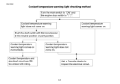
Coolant temperature warning light does not come on . Coolant temperature warning light comes on . Go ahead with the transmission in the neutral position or park position. Ask a Yamaha dealer to " ". Coolant temperature warning light comes on momentarily. Push the start switch with riding. Coolant temperature and electrical circuit are OK. EBU15390 Coolant temperature warning light checking method ACB-09E Turn the main switch to "ON" and the engine stop switch to inspect the electrical circuit. 4-4 Coolant temperature warning light does not come on .
Coolant temperature warning light does not come on . Coolant temperature warning light comes on . Go ahead with the transmission in the neutral position or park position. Ask a Yamaha dealer to " ". Coolant temperature warning light comes on momentarily. Push the start switch with riding. Coolant temperature and electrical circuit are OK. EBU15390 Coolant temperature warning light checking method ACB-09E Turn the main switch to "ON" and the engine stop switch to inspect the electrical circuit. 4-4 Coolant temperature warning light does not come on .
Owners Manual
Page 29
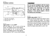
... meter lighting. The engine stop switch controls ignition and can be used at all the lights. 4-7 Engine stop switch " / " Make sure that the starter motor will not start or run when the engine stop switch is set to " ". The engine will not operate properly. If this should happen, remove the battery and recharge it. _ EBU12050 1. EBU00053 Handlebar switches _ CAUTION: Do not use the headlights with the engine turned off all times...
... meter lighting. The engine stop switch controls ignition and can be used at all the lights. 4-7 Engine stop switch " / " Make sure that the starter motor will not start or run when the engine stop switch is set to " ". The engine will not operate properly. If this should happen, remove the battery and recharge it. _ EBU12050 1. EBU00053 Handlebar switches _ CAUTION: Do not use the headlights with the engine turned off all times...
Owners Manual
Page 32
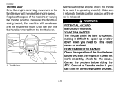
... or solve the problem yourself. 1. Throttle lever 4-10 Consult a Yamaha dealer if you start the engine. EBU00062 Throttle lever Once the engine is running, movement of the throttle lever will return to an idle any time the hand is removed from the throttle lever. WHAT CAN HAPPEN The throttle could cause an accident. Regulate the speed of throttle. If it returns to the idle position as soon...
... or solve the problem yourself. 1. Throttle lever 4-10 Consult a Yamaha dealer if you start the engine. EBU00062 Throttle lever Once the engine is running, movement of the throttle lever will return to an idle any time the hand is removed from the throttle lever. WHAT CAN HAPPEN The throttle could cause an accident. Regulate the speed of throttle. If it returns to the idle position as soon...
Owners Manual
Page 43
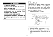
... handling and loss of the ATV. The auxiliary DC jack should only be used when the engine is located at the front right side of stability, which could lead to an accident. Auxiliary DC jack The auxiliary DC jack is running. 1. Auxiliary DC jack cap 2. Start the engine. (See pages 6-1-6-3.) 3. WHAT CAN HAPPEN Uneven adjustment can be used for suitable work lights, radios...
... handling and loss of the ATV. The auxiliary DC jack should only be used when the engine is located at the front right side of stability, which could lead to an accident. Auxiliary DC jack The auxiliary DC jack is running. 1. Auxiliary DC jack cap 2. Start the engine. (See pages 6-1-6-3.) 3. WHAT CAN HAPPEN Uneven adjustment can be used for suitable work lights, radios...
Owners Manual
Page 47
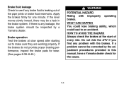
... brakes do not provide proper braking performance, inspect the brake pads for wear. (See pages 8-39-8-40.) WARNING POTENTIAL HAZARD Riding with the brakes. Brake fluid leakage Check to see if any brake fluid is any problem with improperly operating brakes. If a problem cannot be a leak in this manual, have a Yamaha dealer check for one minute. HOW TO AVOID THE HAZARD Always check the brakes at slow speed after starting...
... brakes do not provide proper braking performance, inspect the brake pads for wear. (See pages 8-39-8-40.) WARNING POTENTIAL HAZARD Riding with the brakes. Brake fluid leakage Check to see if any brake fluid is any problem with improperly operating brakes. If a problem cannot be a leak in this manual, have a Yamaha dealer check for one minute. HOW TO AVOID THE HAZARD Always check the brakes at slow speed after starting...
Owners Manual
Page 58
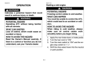
... cold weather. WARNING POTENTIAL HAZARD Operating ATV without being familiar with all control cables work smoothly before you do not understand, ask your Yamaha dealer. 6-1 EBU15110 OPERATION Starting a cold engine WARNING Indicates a potential hazard that could lead to control the ATV, which could cause an accident or injury. Apply the rear brake lever or brake pedal. 2. HOW TO AVOID THE HAZARD Read the Owner's Manual...
... cold weather. WARNING POTENTIAL HAZARD Operating ATV without being familiar with all control cables work smoothly before you do not understand, ask your Yamaha dealer. 6-1 EBU15110 OPERATION Starting a cold engine WARNING Indicates a potential hazard that could lead to control the ATV, which could cause an accident or injury. Apply the rear brake lever or brake pedal. 2. HOW TO AVOID THE HAZARD Read the Owner's Manual...
Owners Manual
Page 59
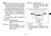
... inspect the respective electric circuit. Position 2 : Cold engine startambient temperature at 0°C (30°F)-30°C (90°F) and warming up position. Starter (choke) 2. G The engine can be started in any gear if the rear brake lever or brake pedal is recommended to shift into neutral or park before starting the engine. _ _ Position 3 : Cold engine startambient temperature above 25°C (80°F) and warm engine start switch. 6-2 However, it...
... inspect the respective electric circuit. Position 2 : Cold engine startambient temperature at 0°C (30°F)-30°C (90°F) and warming up position. Starter (choke) 2. G The engine can be started in any gear if the rear brake lever or brake pedal is recommended to shift into neutral or park before starting the engine. _ _ Position 3 : Cold engine startambient temperature above 25°C (80°F) and warm engine start switch. 6-2 However, it...
Owners Manual
Page 62
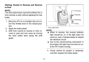
... to inspect the electrical circuit. Check behind for people or obstacles, and then release the brake pedal. 6-5 Apply the brake pedal. 3. If the light does not come on until the ATV starts moving the drive select lever along the shift guide. 1. Shifting: Neutral to Reverse and Reverse to the closed position. 2. Drive select lever NOTE: G When in the engine, the light may not...
... to inspect the electrical circuit. Check behind for people or obstacles, and then release the brake pedal. 6-5 Apply the brake pedal. 3. If the light does not come on until the ATV starts moving the drive select lever along the shift guide. 1. Shifting: Neutral to Reverse and Reverse to the closed position. 2. Drive select lever NOTE: G When in the engine, the light may not...
Owners Manual
Page 90
Make sure that the engine and exhaust pipe will start the engine. You should practice control of your ATV. Once it has warmed up you are thoroughly familiar with the operation of the throttle, brakes, and turning techniques in contact with your ATV. do not allow skin or clothing to start to the closed position, and shift the drive select lever into...
Make sure that the engine and exhaust pipe will start the engine. You should practice control of your ATV. Once it has warmed up you are thoroughly familiar with the operation of the throttle, brakes, and turning techniques in contact with your ATV. do not allow skin or clothing to start to the closed position, and shift the drive select lever into...
Owners Manual
Page 157
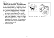
... rear brake light switch in direction b. 3. Rear brake light switch 2. To make the brake light come on later, turn the adjusting nut in direction a. If necessary, adjust the brake light switch as follows. 1. Remove panel B. (See page 8-9 for panel removal and installation procedures.) 2. Install the panel. 1. To make the brake light come on just before braking takes effect. Adjusting nut 8-47 EBU12590 Adjusting the rear brake light switch The rear brake light switch, which is activated by the brake...
... rear brake light switch in direction b. 3. Rear brake light switch 2. To make the brake light come on later, turn the adjusting nut in direction a. If necessary, adjust the brake light switch as follows. 1. Remove panel B. (See page 8-9 for panel removal and installation procedures.) 2. Install the panel. 1. To make the brake light come on just before braking takes effect. Adjusting nut 8-47 EBU12590 Adjusting the rear brake light switch The rear brake light switch, which is activated by the brake...
Owners Manual
Page 158
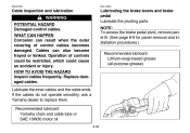
Replace damaged cables. Recommended lubricant: Yamaha chain and cable lube or SAE 10W30 motor oil 8-48 Lubricating the brake levers and brake pedal Lubricate the pivoting parts. WHAT CAN HAPPEN Corrosion can also become frayed or kinked. Lubricate the inner cables and the cable ends. EBU00356 EBU12600 Cable inspection and lubrication WARNING POTENTIAL HAZARD Damaged control cables. Operation of control cables...
Replace damaged cables. Recommended lubricant: Yamaha chain and cable lube or SAE 10W30 motor oil 8-48 Lubricating the brake levers and brake pedal Lubricate the pivoting parts. WHAT CAN HAPPEN Corrosion can also become frayed or kinked. Lubricate the inner cables and the cable ends. EBU00356 EBU12600 Cable inspection and lubrication WARNING POTENTIAL HAZARD Damaged control cables. Operation of control cables...
Owners Manual
Page 164
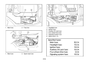
Main fuse 2. Main fuse 2. Headlight fuse Ignition fuse Auxiliary DC jack fuse Four-wheel drive fuse Signaling system fuse Spare fuse (× 3) 1. 1. Fuse box 1. 2. 3. 4. 5. 6. Spare main fuse Specified fuses: Main fuse: Headlight fuse: Ignition fuse: Auxiliary DC jack fuse: Four-wheel drive fuse: Signaling system fuse: 8-54 30.0 A 15.0 A 10.0 A 10.0 A 3.0 A 10.0 A
Main fuse 2. Main fuse 2. Headlight fuse Ignition fuse Auxiliary DC jack fuse Four-wheel drive fuse Signaling system fuse Spare fuse (× 3) 1. 1. Fuse box 1. 2. 3. 4. 5. 6. Spare main fuse Specified fuses: Main fuse: Headlight fuse: Ignition fuse: Auxiliary DC jack fuse: Four-wheel drive fuse: Signaling system fuse: 8-54 30.0 A 15.0 A 10.0 A 10.0 A 3.0 A 10.0 A
Owners Manual
Page 174
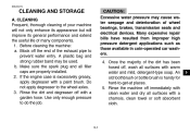
... its appearance but will improve its general performance and extend the useful life of wheel bearings, brakes, transmission seals and electrical devices. Rinse the dirt and degreaser off , wash all surfaces with clean water and dry all filler caps are properly installed. 2. EBU00419 1- Make sure the spark plug and all surfaces with a garden hose. CLEANING AND STORAGE CAUTION: Excessive water pressure may be used.
... its appearance but will improve its general performance and extend the useful life of wheel bearings, brakes, transmission seals and electrical devices. Rinse the dirt and degreaser off , wash all surfaces with clean water and dry all filler caps are properly installed. 2. EBU00419 1- Make sure the spark plug and all surfaces with a garden hose. CLEANING AND STORAGE CAUTION: Excessive water pressure may be used.
Owners Manual
Page 176
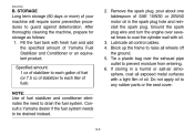
... motor oil in a humid or salt-air atmosphere, coat all exposed metal surfaces with fresh fuel and add the specified amount of Yamaha Fuel Stabilizer and Conditioner or an equivalent product. Do not apply oil to be drained instead. 2. Consult a Yamaha dealer if the fuel system needs to any rubber parts or the seat cover. 9-3 Lubricate all wheels off the ground. 5. EBU00530 B. Ground the spark plug wire and turn...
... motor oil in a humid or salt-air atmosphere, coat all exposed metal surfaces with fresh fuel and add the specified amount of Yamaha Fuel Stabilizer and Conditioner or an equivalent product. Do not apply oil to be drained instead. 2. Consult a Yamaha dealer if the fuel system needs to any rubber parts or the seat cover. 9-3 Lubricate all wheels off the ground. 5. EBU00530 B. Ground the spark plug wire and turn...
Owners Manual
Page 183
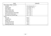
Model Bulb voltage, wattage × quantity: Headlight Tail/brake light Meter lighting Neutral indicator light Reverse indicator light Coolant temperature warning light Park position indicator light Four-wheel drive indicator light Fuses: Main fuse Headlight fuse Ignition fuse Auxiliary DC jack fuse Four-wheel drive fuse Signaling system fuse YFM400FA 12 V 30 W/30.0 W × 2 12 V 5 W/21.0 W × 1 14 V 3.0 W × 1 12 V 1.7 W × 1 12 V 1.7 W × 1 12 V 1.7 W × 1 12 V 1.7 W × 1 12 V 1.7 W × 1 30.0 A 15.0 A 10.0 A 10.0 A 3.0 A 10.0 A 10-6
Model Bulb voltage, wattage × quantity: Headlight Tail/brake light Meter lighting Neutral indicator light Reverse indicator light Coolant temperature warning light Park position indicator light Four-wheel drive indicator light Fuses: Main fuse Headlight fuse Ignition fuse Auxiliary DC jack fuse Four-wheel drive fuse Signaling system fuse YFM400FA 12 V 30 W/30.0 W × 2 12 V 5 W/21.0 W × 1 14 V 3.0 W × 1 12 V 1.7 W × 1 12 V 1.7 W × 1 12 V 1.7 W × 1 12 V 1.7 W × 1 12 V 1.7 W × 1 30.0 A 15.0 A 10.0 A 10.0 A 3.0 A 10.0 A 10-6