
Owners Manual
Page 6
...THE WARNING AND SPECIFICATION LABELS...1-1 SAFETY INFORMATION...2-1 DESCRIPTION AND MACHINE IDENTIFICATION ...3-1 Identification number records...3-2 Key identification number...3-2 Vehicle identification number ...3-3 Model label ...3-3 2 3 CONTROL FUNCTIONS...4-1 Main switch ...4-1 Indicator and warning lights ...4-2 Handlebar switches ...4-5 Throttle lever ...4-6 Speed limiter ...4-8 Front brake lever...4-9 Brake pedal and rear brake lever ...4-9 Parking brake...4-10 Drive select lever ...4-11 Recoil starter...4-11 Fuel tank cap ...4-12 Fuel cock...4-13 Starter (choke) ...4-14 Seat...4-15...
...THE WARNING AND SPECIFICATION LABELS...1-1 SAFETY INFORMATION...2-1 DESCRIPTION AND MACHINE IDENTIFICATION ...3-1 Identification number records...3-2 Key identification number...3-2 Vehicle identification number ...3-3 Model label ...3-3 2 3 CONTROL FUNCTIONS...4-1 Main switch ...4-1 Indicator and warning lights ...4-2 Handlebar switches ...4-5 Throttle lever ...4-6 Speed limiter ...4-8 Front brake lever...4-9 Brake pedal and rear brake lever ...4-9 Parking brake...4-10 Drive select lever ...4-11 Recoil starter...4-11 Fuel tank cap ...4-12 Fuel cock...4-13 Starter (choke) ...4-14 Seat...4-15...
Owners Manual
Page 7
5 PRE-OPERATION CHECKS ...5-1 Front and rear brakes ...5-2 Fuel ...5-4 Engine oil ...5-6 Final gear oil...5-6 Throttle lever ...5-6 Fittings and fasteners...5-7 Lights...5-7 Switches...5-7 Tires ...5-7 How to measure tire pressure...5-9 Tire wear limit...5-10 OPERATION...6-1 Starting a cold engine ...6-1 Starting a warm engine...6-3 Warming up...6-3 Drive select lever operation and reverse driving...6-4 Engine break-in...6-7 Parking ...6-8 Parking on a slope ...6-9 Accessories and loading...6-10 7 6 RIDING YOUR ATV ...7-1 Getting to know your ATV ...7-3 Ride with care and good judgement...
5 PRE-OPERATION CHECKS ...5-1 Front and rear brakes ...5-2 Fuel ...5-4 Engine oil ...5-6 Final gear oil...5-6 Throttle lever ...5-6 Fittings and fasteners...5-7 Lights...5-7 Switches...5-7 Tires ...5-7 How to measure tire pressure...5-9 Tire wear limit...5-10 OPERATION...6-1 Starting a cold engine ...6-1 Starting a warm engine...6-3 Warming up...6-3 Drive select lever operation and reverse driving...6-4 Engine break-in...6-7 Parking ...6-8 Parking on a slope ...6-9 Accessories and loading...6-10 7 6 RIDING YOUR ATV ...7-1 Getting to know your ATV ...7-3 Ride with care and good judgement...
Owners Manual
Page 8
... Owner's manual and tool kit...8-1 Periodic maintenance/ lubrication ...8-3 Panel removal and installation ...8-6 Engine oil and oil filter cartridge ...8-7 Final gear oil ...8-13 Spark plug inspection...8-16 Air filter element cleaning...8-19 V-belt cooling duct check hose ...8-22 V-belt case drain plug...8-23 Spark arrester cleaning ...8-23 Carburetor adjustment...8-25 Idle speed adjustment ...8-25 Valve clearance adjustment ...8-26 Select lever safety system cable adjustment ...8-26 Throttle lever adjustment...8-27 Front brake pad check ...8-28 Rear brake shoe inspection ...8-28 Brake fluid...
... Owner's manual and tool kit...8-1 Periodic maintenance/ lubrication ...8-3 Panel removal and installation ...8-6 Engine oil and oil filter cartridge ...8-7 Final gear oil ...8-13 Spark plug inspection...8-16 Air filter element cleaning...8-19 V-belt cooling duct check hose ...8-22 V-belt case drain plug...8-23 Spark arrester cleaning ...8-23 Carburetor adjustment...8-25 Idle speed adjustment ...8-25 Valve clearance adjustment ...8-26 Select lever safety system cable adjustment ...8-26 Throttle lever adjustment...8-27 Front brake pad check ...8-28 Rear brake shoe inspection ...8-28 Brake fluid...

Owners Manual
Page 20
...: The machine you have purchased may differ slightly from those shown in the figures of this manual. 3-1 Brake pedal 7. Fuses 11. V-belt cooling duct check hose 14. Drive select lever 20. Fuel tank cap 22. Starter (choke) 19. EBU00032 1- Fuel cock 9. Main switch 21. Throttle lever 23. Rear shock absorber assembly spring preload adjusting ring 2. Spark arrester 3. Spark plug 5. Air filter case 10. Front shock absorber assembly spring preload adjusting ring 13. Engine oil dipstick 16. Left handlebar...
...: The machine you have purchased may differ slightly from those shown in the figures of this manual. 3-1 Brake pedal 7. Fuses 11. V-belt cooling duct check hose 14. Drive select lever 20. Fuel tank cap 22. Starter (choke) 19. EBU00032 1- Fuel cock 9. Main switch 21. Throttle lever 23. Rear shock absorber assembly spring preload adjusting ring 2. Spark arrester 3. Spark plug 5. Air filter case 10. Front shock absorber assembly spring preload adjusting ring 13. Engine oil dipstick 16. Left handlebar...
Owners Manual
Page 26
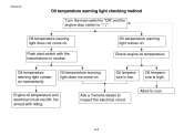
... the electrical circuit. 4-4 Engine oil temperature and electrical circuit are OK. Ask a Yamaha dealer to cool. Oil temperature warning light comes on momentarily. Oil temperature is low. Go ahead with the transmission in neutral. Push start switch with riding. Oil temperature warning light does not come on . Oil temperature warning light comes on . EBU00733 Oil temperature warning light checking method ACB-10E Turn the main switch to "ON" and the engine stop switch to " ". Oil temperature warning light does...
... the electrical circuit. 4-4 Engine oil temperature and electrical circuit are OK. Ask a Yamaha dealer to cool. Oil temperature warning light comes on momentarily. Oil temperature is low. Go ahead with the transmission in neutral. Push start switch with riding. Oil temperature warning light does not come on . Oil temperature warning light comes on . EBU00733 Oil temperature warning light checking method ACB-10E Turn the main switch to "ON" and the engine stop switch to " ". Oil temperature warning light does...
Owners Manual
Page 27
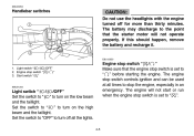
... switch controls ignition and can be used at all the lights. 4-5 Engine stop switch " / " Make sure that the starter motor will not start or run when the engine stop switch " / " 3. Light switch " / /OFF" 2. Set the switch to " " to " " before starting the engine. Engine stop switch is set to " ". If this should happen, remove the battery and recharge it. _ EBU12050 1. EBU00053 Handlebar switches _ CAUTION: Do not use the headlights with the engine turned off all times...
... switch controls ignition and can be used at all the lights. 4-5 Engine stop switch " / " Make sure that the starter motor will not start or run when the engine stop switch " / " 3. Light switch " / /OFF" 2. Set the switch to " " to " " before starting the engine. Engine stop switch is set to " ". If this should happen, remove the battery and recharge it. _ EBU12050 1. EBU00053 Handlebar switches _ CAUTION: Do not use the headlights with the engine turned off all times...
Owners Manual
Page 29
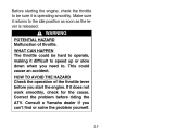
... ATV. Correct the problem before you start the engine. This could be sure it is released. If it returns to the idle position as soon as the lever is operating smoothly. WHAT CAN HAPPEN The throttle could cause an accident. Before starting the engine, check the throttle to be hard to operate, making it difficult to speed up or slow...
... ATV. Correct the problem before you start the engine. This could be sure it is released. If it returns to the idle position as soon as the lever is operating smoothly. WHAT CAN HAPPEN The throttle could cause an accident. Before starting the engine, check the throttle to be hard to operate, making it difficult to speed up or slow...

Owners Manual
Page 44
... find any leakage, the brake system should be a leak in this manual, have a Yamaha dealer check for the cause. 5-3 Brake operation Test the brakes at the start of the front brake. HOW TO AVOID THE HAZARD Always check the brakes at slow speed after starting out to an accident. If the brakes do not provide proper braking performance, inspect the brake pads and shoes for one...
... find any leakage, the brake system should be a leak in this manual, have a Yamaha dealer check for the cause. 5-3 Brake operation Test the brakes at the start of the front brake. HOW TO AVOID THE HAZARD Always check the brakes at slow speed after starting out to an accident. If the brakes do not provide proper braking performance, inspect the brake pads and shoes for one...
Owners Manual
Page 48
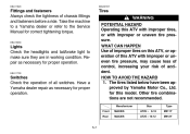
... or uneven tire pressure, may cause loss of control, increasing your risk of this ATV with improper or uneven tire pressure. EBU11700 Switches Check the operation of chassis fittings and fasteners before a ride. Manufacturer Front Rear MAXXIS MAXXIS Size AT25 × 8-12 AT25 × 10-12 Type M911Y M912Y 5-7 ACE-01E Lights Check the headlights and tail/brake light to the Service Manual for proper...
... or uneven tire pressure, may cause loss of control, increasing your risk of this ATV with improper or uneven tire pressure. EBU11700 Switches Check the operation of chassis fittings and fasteners before a ride. Manufacturer Front Rear MAXXIS MAXXIS Size AT25 × 8-12 AT25 × 10-12 Type M911Y M912Y 5-7 ACE-01E Lights Check the headlights and tail/brake light to the Service Manual for proper...
Owners Manual
Page 52
Turn the main switch to "ON" and the engine stop switch to "ON". 3. HOW TO AVOID THE HAZARD Read the Owner's Manual carefully. HOW TO AVOID THE HAZARD When riding in cold weather, always make sure all controls. Shift the drive select lever into the neutral position. WHAT CAN HAPPEN Loss of control, which could lead to control the ATV, which could result...
Turn the main switch to "ON" and the engine stop switch to "ON". 3. HOW TO AVOID THE HAZARD Read the Owner's Manual carefully. HOW TO AVOID THE HAZARD When riding in cold weather, always make sure all controls. Shift the drive select lever into the neutral position. WHAT CAN HAPPEN Loss of control, which could lead to control the ATV, which could result...
Owners Manual
Page 53
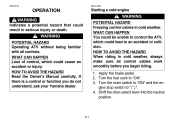
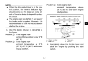
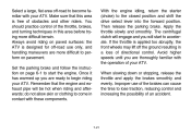
... inspect the electric circuit. Starter (choke) 2. NOTE: G When the drive select lever is recommended to shift into neutral before starting the engine. _ _ Position 3: Cold engine startambient temperature above 25 °C (80 °F) and warm engine start switch. 6-2 G The engine can be started in reference to the figure: Position 1: Cold engine startambient temperature below 5 °C (40 °F). Use the starter (choke) in any gear if the brake pedal is...
... inspect the electric circuit. Starter (choke) 2. NOTE: G When the drive select lever is recommended to shift into neutral before starting the engine. _ _ Position 3: Cold engine startambient temperature above 25 °C (80 °F) and warm engine start switch. 6-2 G The engine can be started in reference to the figure: Position 1: Cold engine startambient temperature below 5 °C (40 °F). Use the starter (choke) in any gear if the brake pedal is...
Owners Manual
Page 59
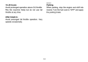
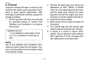
EBU00211 10-20 hours: Avoid prolonged operation above 3/4 throttle. Vary speeds occasionally. Parking When parking, stop the engine and shift into neutral. Rev the machine freely but do not use full throttle at any time. Turn the fuel cock to "OFF" and apply the parking brake. 6-8 After break-in: Avoid prolonged full throttle operation.
EBU00211 10-20 hours: Avoid prolonged operation above 3/4 throttle. Vary speeds occasionally. Parking When parking, stop the engine and shift into neutral. Rev the machine freely but do not use full throttle at any time. Turn the fuel cock to "OFF" and apply the parking brake. 6-8 After break-in: Avoid prolonged full throttle operation.
Owners Manual
Page 84
... applied too abruptly, the front wheels may lift off -road use of the brakes can cause the tires to accelerate. Avoid higher speeds until you are ready to the closed position and shift the drive select lever into the forward position. Improper use only, and handling maneuvers are more difficult terrain. Set the parking brake and follow the instruction on pavement...
... applied too abruptly, the front wheels may lift off -road use of the brakes can cause the tires to accelerate. Avoid higher speeds until you are ready to the closed position and shift the drive select lever into the forward position. Improper use only, and handling maneuvers are more difficult terrain. Set the parking brake and follow the instruction on pavement...
Owners Manual
Page 105
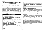
... this manual is an obligation of the machine owner. EBU00515 1- PERIODIC MAINTENANCE AND ADJUSTMENT Periodic inspection, adjustment and lubrication will keep your own preventive maintenance and minor repairs. Put the owner's tool kit and low-pressure tire gauge under the seat. Electrical components can cause shocks or can catch clothing or parts of the seat as shown. Safety is intended to properly tighten nuts and bolts...
... this manual is an obligation of the machine owner. EBU00515 1- PERIODIC MAINTENANCE AND ADJUSTMENT Periodic inspection, adjustment and lubrication will keep your own preventive maintenance and minor repairs. Put the owner's tool kit and low-pressure tire gauge under the seat. Electrical components can cause shocks or can catch clothing or parts of the seat as shown. Safety is intended to properly tighten nuts and bolts...
Owners Manual
Page 139
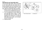
....) 2. If necessary, adjust the brake light switch as follows. 1. EBU12590 Adjusting the rear brake light switch The rear brake light switch, which is activated by the brake pedal and rear brake lever, is properly adjusted when the brake light comes on later, turn the adjusting nut in place. Install the panel. 1. To make the brake light come on just before braking takes effect. Turn the adjusting nut while holding the rear brake light switch in direction a. Rear brake light switch 2.
....) 2. If necessary, adjust the brake light switch as follows. 1. EBU12590 Adjusting the rear brake light switch The rear brake light switch, which is activated by the brake pedal and rear brake lever, is properly adjusted when the brake light comes on later, turn the adjusting nut in place. Install the panel. 1. To make the brake light come on just before braking takes effect. Turn the adjusting nut while holding the rear brake light switch in direction a. Rear brake light switch 2.
Owners Manual
Page 140
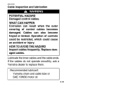
... result when the outer covering of controls could be restricted, which could cause an accident or injury. Lubricate the inner cables and the cable ends. Recommended lubricant: Yamaha chain and cable lube or SAE 10W30 motor oil 8-36 If the cables do not operate smoothly, ask a Yamaha dealer to replace them. Replace damaged cables. Operation of control cables becomes damaged.
... result when the outer covering of controls could be restricted, which could cause an accident or injury. Lubricate the inner cables and the cable ends. Recommended lubricant: Yamaha chain and cable lube or SAE 10W30 motor oil 8-36 If the cables do not operate smoothly, ask a Yamaha dealer to replace them. Replace damaged cables. Operation of control cables becomes damaged.
Owners Manual
Page 146
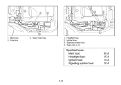
Spare main fuse 1. 2. 3. 4. Main fuse 3. Headlight fuse Ignition fuse Signaling system fuse Spare fuse (× 2) Specified fuses: Main fuse: Headlight fuse: Ignition fuse: Signaling system fuse: 30 A 15 A 15 A 10 A 8-42 Fuse box 2. 1.
Spare main fuse 1. 2. 3. 4. Main fuse 3. Headlight fuse Ignition fuse Signaling system fuse Spare fuse (× 2) Specified fuses: Main fuse: Headlight fuse: Ignition fuse: Signaling system fuse: 30 A 15 A 15 A 10 A 8-42 Fuse box 2. 1.
Owners Manual
Page 154
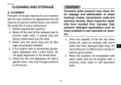
... 14 A. Make sure the spark plug and all surfaces with clean water and dry all filler caps are properly installed. 2. Rinse the machine off the end of wheel bearings, brakes, transmission seals and electrical devices. CLEANING Frequent, thorough cleaning of your machine will not only enhance its appearance but will improve its general performance and extend the useful life of the...
... 14 A. Make sure the spark plug and all surfaces with clean water and dry all filler caps are properly installed. 2. Rinse the machine off the end of wheel bearings, brakes, transmission seals and electrical devices. CLEANING Frequent, thorough cleaning of your machine will not only enhance its appearance but will improve its general performance and extend the useful life of the...
Owners Manual
Page 156
... procedures to coat the cylinder wall with oil. 3. Ground the spark plug wire and turn the engine over the exhaust pipe outlet to raise all wheels off the ground. 5. EBU00530 B. Specified amount: 1 oz of stabilizer to each gallon of fuel (or 7.5 cc of stabilizer to each liter of fuel) NOTE: Use of SAE 10W30 or 20W40 motor oil in a humid or salt-air atmosphere, coat all control cables. 4.
... procedures to coat the cylinder wall with oil. 3. Ground the spark plug wire and turn the engine over the exhaust pipe outlet to raise all wheels off the ground. 5. EBU00530 B. Specified amount: 1 oz of stabilizer to each gallon of fuel (or 7.5 cc of stabilizer to each liter of fuel) NOTE: Use of SAE 10W30 or 20W40 motor oil in a humid or salt-air atmosphere, coat all control cables. 4.
Owners Manual
Page 163
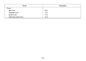
Model Fuses: Main fuse Headlight fuse Ignition fuse Signaling system fuse 30 A 15 A 15 A 10 A YFM350BA 10-6
Model Fuses: Main fuse Headlight fuse Ignition fuse Signaling system fuse 30 A 15 A 15 A 10 A YFM350BA 10-6