

Owners Manual
Page 12
... to the motorcycle before riding. Carefully inspect the accessory before using it does not in any accessories. Shifting weights can create unstable handling or a slow steering response. SAFETY INFORMATION Loading The total weight of the operator, passenger, accessories and cargo must personally be kept as possible. Cargo and accessory weight should be responsible for use of non-Yamaha accessories. Check accessory mounts and cargo restraints frequently. 3.
... to the motorcycle before riding. Carefully inspect the accessory before using it does not in any accessories. Shifting weights can create unstable handling or a slow steering response. SAFETY INFORMATION Loading The total weight of the operator, passenger, accessories and cargo must personally be kept as possible. Cargo and accessory weight should be responsible for use of non-Yamaha accessories. Check accessory mounts and cargo restraints frequently. 3.
Owners Manual
Page 13
... the vicinity of lights or engine power. 1 Gasoline and exhaust gas 1. Take care not to lift the motorcycle, or the motorcycle may limit control ability, therefore, such accessories are not recommended. 2. b. Always operate your motorcycle in a closed area. SAFETY INFORMATION a. c. If accessories are poisonous and may cause loss of the motorcycle due to improper weight distribution or aerodynamic changes. When parking the motorcycle...
... the vicinity of lights or engine power. 1 Gasoline and exhaust gas 1. Take care not to lift the motorcycle, or the motorcycle may limit control ability, therefore, such accessories are not recommended. 2. b. Always operate your motorcycle in a closed area. SAFETY INFORMATION a. c. If accessories are poisonous and may cause loss of the motorcycle due to improper weight distribution or aerodynamic changes. When parking the motorcycle...
Owners Manual
Page 16
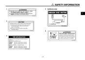
... to connect breather hose after installing battery. 3JL-28177-A0 5 WARNING PASS LEAD WIRES THROUGH HOLE, as follows. Electrolyte will damage metal parts or paint. This could cause the engine to stop running and lights to fail, which could result from improper routing. SAFETY INFORMATION 1 4 California only 1 2 CAUTION Read owner's manual before servicing battery. If electrolyte spills, wash area with fresh water immediately. Be...
... to connect breather hose after installing battery. 3JL-28177-A0 5 WARNING PASS LEAD WIRES THROUGH HOLE, as follows. Electrolyte will damage metal parts or paint. This could cause the engine to stop running and lights to fail, which could result from improper routing. SAFETY INFORMATION 1 4 California only 1 2 CAUTION Read owner's manual before servicing battery. If electrolyte spills, wash area with fresh water immediately. Be...

Owners Manual
Page 21
INSTRUMENT AND CONTROL FUNCTIONS Main switch ...3-1 Indicator and warning lights ...3-1 Speedometer unit ...3-2 Tachometer ...3-3 Coolant temperature gauge ...3-3 Handlebar switches ...3-3 Clutch lever ...3-5 Shift pedal ...3-5 Brake lever ...3-5 Brake pedal ...3-6 Fuel tank cap ...3-6 Fuel ...3-7 Starter (choke) lever ...3-8 Steering lock ...3-9 Rider seat ...3-9 Helmet holder ...3-10 Adjusting the front fork ...3-11 Adjusting the shock absorber assemblies ...3-12 Matching the front and rear suspension settings ...3-15 V-Boost ...3-16 Sidestand ...3-17 Ignition circuit cut-off system ...3-17...
INSTRUMENT AND CONTROL FUNCTIONS Main switch ...3-1 Indicator and warning lights ...3-1 Speedometer unit ...3-2 Tachometer ...3-3 Coolant temperature gauge ...3-3 Handlebar switches ...3-3 Clutch lever ...3-5 Shift pedal ...3-5 Brake lever ...3-5 Brake pedal ...3-6 Fuel tank cap ...3-6 Fuel ...3-7 Starter (choke) lever ...3-8 Steering lock ...3-9 Rider seat ...3-9 Helmet holder ...3-10 Adjusting the front fork ...3-11 Adjusting the shock absorber assemblies ...3-12 Matching the front and rear suspension settings ...3-15 V-Boost ...3-16 Sidestand ...3-17 Ignition circuit cut-off system ...3-17...
Owners Manual
Page 22
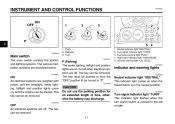
... "P". The key can be turned to be removed. INSTRUMENT AND CONTROL FUNCTIONS EAU00027 3 1. Neutral indicator light "NEUTRAL" Turn signal indicator light "TURN" Fuel level warning light "FUEL" High beam indicator light "HIGH BEAM" Oil level warning light "OIL LEVEL" EAU03034 Indicator and warning lights EAU00062 CAUTION: Do not use the parking position for an extended length of time, otherwise the battery may discharge. _ _ Neutral indicator light "NEUTRAL" This indicator light comes on , and the engine can be removed. EAU00032 ON All electrical systems...
... "P". The key can be turned to be removed. INSTRUMENT AND CONTROL FUNCTIONS EAU00027 3 1. Neutral indicator light "NEUTRAL" Turn signal indicator light "TURN" Fuel level warning light "FUEL" High beam indicator light "HIGH BEAM" Oil level warning light "OIL LEVEL" EAU03034 Indicator and warning lights EAU00062 CAUTION: Do not use the parking position for an extended length of time, otherwise the battery may discharge. _ _ Neutral indicator light "NEUTRAL" This indicator light comes on , and the engine can be removed. EAU00032 ON All electrical systems...
Owners Manual
Page 23
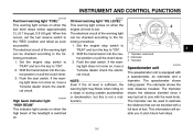
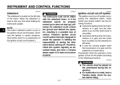
... the reset knob. Set the engine stop switch to "RUN" and turn the key to the following procedure. 1. INSTRUMENT AND CONTROL FUNCTIONS EAU04166 EAU04167 Fuel level warning light "FUEL" This warning light comes on , have a Yamaha dealer check the electrical circuit. If the warning light does not come on when the fuel level drops below approximately 3 L (0.7 Imp gal, 0.8 US gal). Shift the transmission into the neutral position or pull the clutch lever. 3.
... the reset knob. Set the engine stop switch to "RUN" and turn the key to the following procedure. 1. INSTRUMENT AND CONTROL FUNCTIONS EAU04166 EAU04167 Fuel level warning light "FUEL" This warning light comes on , have a Yamaha dealer check the electrical circuit. If the warning light does not come on when the fuel level drops below approximately 3 L (0.7 Imp gal, 0.8 US gal). Shift the transmission into the neutral position or pull the clutch lever. 3.

Owners Manual
Page 24
.... INSTRUMENT AND CONTROL FUNCTIONS 3 1. If the needle reaches or enters the red zone, stop the motorcycle and let the engine cool. (See page 6-48 for the low beam. When released, the switch returns to the left. Horn switch "HORN" EAU00118 Tachometer The electric tachometer allows the rider to monitor the engine speed and keep it is overheated. @ @ Turn signal switch "TURN" To signal a right-hand turn , push the switch to...
.... INSTRUMENT AND CONTROL FUNCTIONS 3 1. If the needle reaches or enters the red zone, stop the motorcycle and let the engine cool. (See page 6-48 for the low beam. When released, the switch returns to the left. Horn switch "HORN" EAU00118 Tachometer The electric tachometer allows the rider to monitor the engine speed and keep it is overheated. @ @ Turn signal switch "TURN" To signal a right-hand turn , push the switch to...
Owners Manual
Page 25
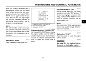
... switch should be canceled manually by pushing the switch in case of fuel remain in the "ON" position. EAU00141 Start switch "START" Push this switch to "ON". 1. If the fuel warning light comes on while riding, set the switch back to crank the engine with a self-canceling system, the turn signal lights will self-cancel after it has returned to "RUN" before starting the engine. @ @ 3-4 Fuel reserve switch "FUEL" 3. Start switch "START" EAU04822 3 NOTE: After switching...
... switch should be canceled manually by pushing the switch in case of fuel remain in the "ON" position. EAU00141 Start switch "START" Push this switch to "ON". 1. If the fuel warning light comes on while riding, set the switch back to crank the engine with a self-canceling system, the turn signal lights will self-cancel after it has returned to "RUN" before starting the engine. @ @ 3-4 Fuel reserve switch "FUEL" 3. Start switch "START" EAU04822 3 NOTE: After switching...

Owners Manual
Page 28
.... 3. INSTRUMENT AND CONTROL FUNCTIONS To install the fuel tank cap 1. Slide the rider seat backrest rearward and push it may deteriorate painted surfaces or plastic parts. @ @ EAU04265 3 1. Fuel level EAU03753 Fuel Make sure that the fuel tank cap is sufficient fuel in the lock and with the key inserted in the tank. Turn the key counterclockwise to the bottom of leaded gasoline will cause severe damage to internal engine...
.... 3. INSTRUMENT AND CONTROL FUNCTIONS To install the fuel tank cap 1. Slide the rider seat backrest rearward and push it may deteriorate painted surfaces or plastic parts. @ @ EAU04265 3 1. Fuel level EAU03753 Fuel Make sure that the fuel tank cap is sufficient fuel in the lock and with the key inserted in the tank. Turn the key counterclockwise to the bottom of leaded gasoline will cause severe damage to internal engine...
Owners Manual
Page 38
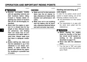
..., have a Yamaha dealer repair it if it with the sidestand down, or if the sidestand cannot be placed on the left side of the ignition circuit cut -off system (comprising the sidestand switch, clutch switch and neutral switch) has the following procedure. G It prevents starting when the transmission is in certain situations. (See further down for an explanation of control. G _ 3-17...
..., have a Yamaha dealer repair it if it with the sidestand down, or if the sidestand cannot be placed on the left side of the ignition circuit cut -off system (comprising the sidestand switch, clutch switch and neutral switch) has the following procedure. G It prevents starting when the transmission is in certain situations. (See further down for an explanation of control. G _ 3-17...

Owners Manual
Page 42
... for damage. Check tire condition and tread depth. If soft or spongy, have Yamaha dealer check vehicle. • Check fluid level. • Fill with distilled water if necessary. 6-31 6-32 6-32 - - 3-17 6-35-6-38 4-2 Correct if necessary. 6-22, 6-31 Control cables 6-30 4 6-23-6-25 Wheels and tires Brake and shift pedals Brake and clutch levers Centerstand, sidestand Chassis fasteners Instruments, lights, signals and switches Sidestand switch Battery • Make...
... for damage. Check tire condition and tread depth. If soft or spongy, have Yamaha dealer check vehicle. • Check fluid level. • Fill with distilled water if necessary. 6-31 6-32 6-32 - - 3-17 6-35-6-38 4-2 Correct if necessary. 6-22, 6-31 Control cables 6-30 4 6-23-6-25 Wheels and tires Brake and shift pedals Brake and clutch levers Centerstand, sidestand Chassis fasteners Instruments, lights, signals and switches Sidestand switch Battery • Make...
Owners Manual
Page 45
... any control or function that the engine stop switch is in the neutral position. Always make sure that you do not thoroughly understand. Consult a Yamaha dealer regarding any length of the following conditions must be blocked and performance will be met: G The transmission is set to put anything near the air cleaner intake, otherwise air intake will suffer. Starting and warming up . Turn the key to...
... any control or function that the engine stop switch is in the neutral position. Always make sure that you do not thoroughly understand. Consult a Yamaha dealer regarding any length of the following conditions must be blocked and performance will be met: G The transmission is set to put anything near the air cleaner intake, otherwise air intake will suffer. Starting and warming up . Turn the key to...
Owners Manual
Page 46
... warning light again. After starting , stop the engine, and then check the engine oil level and the vehicle for starter (choke) operation.) 4. ECA00055 CAUTION: For maximum engine life, always warm the engine up before starting off after starting with sufficient fuel, have a Yamaha dealer check the electrical circuit. NOTE: When the transmission is in the neutral position, the neutral indicator light should be as short as possible to start, release the start switch...
... warning light again. After starting , stop the engine, and then check the engine oil level and the vehicle for starter (choke) operation.) 4. ECA00055 CAUTION: For maximum engine life, always warm the engine up before starting off after starting with sufficient fuel, have a Yamaha dealer check the electrical circuit. NOTE: When the transmission is in the neutral position, the neutral indicator light should be as short as possible to start, release the start switch...
Owners Manual
Page 48
... or runs very roughly, pull the clutch lever in and use the clutch while changing gears to avoid damaging the engine, transmission, and drive train, which are not designed to stop the motorcycle. 3. Shift the transmission into the neutral position.) 6. Inadequate lubrication may damage the transmission. The neutral indicator light should come on page 5-5, close the throttle, and at the same time, quickly pull the clutch lever...
... or runs very roughly, pull the clutch lever in and use the clutch while changing gears to avoid damaging the engine, transmission, and drive train, which are not designed to stop the motorcycle. 3. Shift the transmission into the neutral position.) 6. Inadequate lubrication may damage the transmission. The neutral indicator light should come on page 5-5, close the throttle, and at the same time, quickly pull the clutch lever...
Owners Manual
Page 51
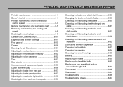
... maintenance ...6-1 Owner's tool kit ...6-1 Periodic maintenance chart for emission control system ...6-3 General maintenance and lubrication chart ...6-5 Removing and installing the cowling and panels ...6-8 Checking the spark plugs ...6-9 Canister (for California only) ...6-11 Engine oil and oil filter cartridge ...6-11 Final gear oil ...6-15 Coolant ...6-16 Cleaning the air filter element ...6-21 Adjusting the carburetors ...6-22 Adjusting the throttle cable free play ...6-22 Adjusting the valve clearance ...6-22 Tires ...6-23 Cast wheels ...6-25 Accessories...
... maintenance ...6-1 Owner's tool kit ...6-1 Periodic maintenance chart for emission control system ...6-3 General maintenance and lubrication chart ...6-5 Removing and installing the cowling and panels ...6-8 Checking the spark plugs ...6-9 Canister (for California only) ...6-11 Engine oil and oil filter cartridge ...6-11 Final gear oil ...6-15 Coolant ...6-16 Cleaning the air filter element ...6-21 Adjusting the carburetors ...6-22 Adjusting the throttle cable free play ...6-22 Adjusting the valve clearance ...6-22 Tires ...6-23 Cast wheels ...6-25 Accessories...

Owners Manual
Page 58
... the maintenance intervals starting from 4,000 mi (7,000 km) or 6 months. _ _ EAU03892 6 NOTE: G The air filter needs more frequent service if you are riding in unusually wet or dusty areas. Regularly check the brake and clutch fluid levels and fill the reservoirs as required. • Replace the oil seals on the inner parts of the brake or clutch master cylinders, caliper cylinders and clutch release cylinder every...
... the maintenance intervals starting from 4,000 mi (7,000 km) or 6 months. _ _ EAU03892 6 NOTE: G The air filter needs more frequent service if you are riding in unusually wet or dusty areas. Regularly check the brake and clutch fluid levels and fill the reservoirs as required. • Replace the oil seals on the inner parts of the brake or clutch master cylinders, caliper cylinders and clutch release cylinder every...

Owners Manual
Page 79
... the braking performance, which allows you to check the brake pad wear without having to the point that the wear indicator almost touches the brake disc, have a Yamaha dealer bleed the system before braking takes effect. Turn the adjusting nut while holding the rear brake light switch in place. Rear brake light switch adjusting nut EAU00713 1. If a brake pad has worn to disassemble the brake. PERIODIC MAINTENANCE AND MINOR REPAIR EW000109 WARNING...
... the braking performance, which allows you to check the brake pad wear without having to the point that the wear indicator almost touches the brake disc, have a Yamaha dealer bleed the system before braking takes effect. Turn the adjusting nut while holding the rear brake light switch in place. Rear brake light switch adjusting nut EAU00713 1. If a brake pad has worn to disassemble the brake. PERIODIC MAINTENANCE AND MINOR REPAIR EW000109 WARNING...

Owners Manual
Page 90
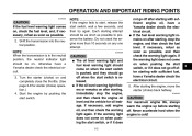
... fuse immediately blows again, have a Yamaha dealer check the electrical system. 30 A 15 A 10 A 10 A 10 A Specified fuses: Main fuse: Headlight fuse: Signaling system fuse: Radiator fan fuse: Ignition fuse: 6-39 Turn the key to the electrical system and possibly a fire. @ @ 1. Headlight fuse Signaling system fuse Ignition fuse Radiator fan fuse Spare fuse (× 2) 3. PERIODIC MAINTENANCE AND MINOR REPAIR EC000103 CAUTION: Do not use a fuse of the specified amperage. 1. 2. 3. 4. 5. Spare main fuse EAU01664 Replacing the fuses 6 The main fuse box is located under the rider seat...
... fuse immediately blows again, have a Yamaha dealer check the electrical system. 30 A 15 A 10 A 10 A 10 A Specified fuses: Main fuse: Headlight fuse: Signaling system fuse: Radiator fan fuse: Ignition fuse: 6-39 Turn the key to the electrical system and possibly a fire. @ @ 1. Headlight fuse Signaling system fuse Ignition fuse Radiator fan fuse Spare fuse (× 2) 3. PERIODIC MAINTENANCE AND MINOR REPAIR EC000103 CAUTION: Do not use a fuse of the specified amperage. 1. 2. 3. 4. 5. Spare main fuse EAU01664 Replacing the fuses 6 The main fuse box is located under the rider seat...

Owners Manual
Page 111
SPECIFICATIONS Bulb voltage, wattage × quantity Headlight Tail/brake light Front turn signal/position light Rear turn signal light Meter lighting Neutral indicator light High beam indicator light Turn signal indicator light Fuel level warning light Oil level warning light Fuses Main fuse Headlight fuse Signaling system fuse Radiator fan fuse Ignition fuse 30 A 15 A 10 A 10 A 10 A 12 V, 60/55 W × 1 12 V, 8/27 W × 2 12 V, 27/8 W × 2 12 V, 27 W × 2 14 V, 3 W × 2 14 V, 3 W × 1 14 V, 3 W × 1 14 V, 3 W × 1 14 V, 3 W × 1 14 V, 3 W × 1 8 8-4
SPECIFICATIONS Bulb voltage, wattage × quantity Headlight Tail/brake light Front turn signal/position light Rear turn signal light Meter lighting Neutral indicator light High beam indicator light Turn signal indicator light Fuel level warning light Oil level warning light Fuses Main fuse Headlight fuse Signaling system fuse Radiator fan fuse Ignition fuse 30 A 15 A 10 A 10 A 10 A 12 V, 60/55 W × 1 12 V, 8/27 W × 2 12 V, 27/8 W × 2 12 V, 27 W × 2 14 V, 3 W × 2 14 V, 3 W × 1 14 V, 3 W × 1 14 V, 3 W × 1 14 V, 3 W × 1 14 V, 3 W × 1 8 8-4

Owners Manual
Page 123
... Clutch lever free play ...6-26 Coolant ...6-16 Changing...6-17 Checking ...6-16 Coolant temperature gauge ...3-3 Cowling and panels, removing and installing ...6-8 R Rear suspension, lubricating ...6-33 Rider seat ...3-9 S Safety defects, reporting ...9-3 Safety information ...1-1 Shifting...5-3 Decelerating ...5-4 Shift points...5-5 Starting out and accelerating ...5-4 Shift pedal...3-5 Shock absorber assemblies, adjusting ...3-12 Sidestand...3-17 Spark plugs, checking ...6-9 I Identification numbers ...9-1 Ignition circuit cut-off system...3-17 Indicator and warning lights ...3-1 K Key...
... Clutch lever free play ...6-26 Coolant ...6-16 Changing...6-17 Checking ...6-16 Coolant temperature gauge ...3-3 Cowling and panels, removing and installing ...6-8 R Rear suspension, lubricating ...6-33 Rider seat ...3-9 S Safety defects, reporting ...9-3 Safety information ...1-1 Shifting...5-3 Decelerating ...5-4 Shift points...5-5 Starting out and accelerating ...5-4 Shift pedal...3-5 Shock absorber assemblies, adjusting ...3-12 Sidestand...3-17 Spark plugs, checking ...6-9 I Identification numbers ...9-1 Ignition circuit cut-off system...3-17 Indicator and warning lights ...3-1 K Key...