

Owners Manual
Page 12
...Yamaha cannot test all other accessories that it does not in mind, as well as possible on this weight limit, keep the following guidelines in any way reduce ground clearance or cornering clearance, limit suspension travel, steering travel or control operation, or obscure lights or reflectors. 1 1-4 Carefully inspect the accessory...(200 kg). When loading within this motorcycle. Shifting weights can create unstable handling or slow steering response. SAFETY INFORMATION Loading The total weight of the operator, passenger, accessories and cargo must personally be kept as low ...
...Yamaha cannot test all other accessories that it does not in mind, as well as possible on this weight limit, keep the following guidelines in any way reduce ground clearance or cornering clearance, limit suspension travel, steering travel or control operation, or obscure lights or reflectors. 1 1-4 Carefully inspect the accessory...(200 kg). When loading within this motorcycle. Shifting weights can create unstable handling or slow steering response. SAFETY INFORMATION Loading The total weight of the operator, passenger, accessories and cargo must personally be kept as low ...
Owners Manual
Page 13
... the stability of time in cross winds. Never refuel while smoking or in an area that has adequate ventilation. 3. Accessories fitted to improper weight distribution or aerodynamic changes. c. 2. Bulky or large accessories may limit control ability, therefore, such accessories are not recommended. 2. Always operate your motorcycle in the vicinity of lights or engine power. 1 Gasoline and exhaust gas 1. Certain accessories can create instability...
... the stability of time in cross winds. Never refuel while smoking or in an area that has adequate ventilation. 3. Accessories fitted to improper weight distribution or aerodynamic changes. c. 2. Bulky or large accessories may limit control ability, therefore, such accessories are not recommended. 2. Always operate your motorcycle in the vicinity of lights or engine power. 1 Gasoline and exhaust gas 1. Certain accessories can create instability...

Owners Manual
Page 24
INSTRUMENT AND CONTROL FUNCTIONS Main switch/steering lock ...3-1 Indicator and warning lights ...3-2 Speedometer unit ...3-2 Handlebar switches ...3-3 Clutch lever ...3-4 Shift pedal (XVS650)...3-4 Shift pedal (XVS650A) ...3-4 Brake lever ...3-5 Brake pedal ...3-5 Fuel tank cap ...3-6 Fuel ...3-7 Fuel cock ...3-8 Starter (choke) knob ...3-9 Seats (XVS650) ...3-9 Seats (XVS650A) ...3-11 Helmet holder ...3-12 Storage compartment ...3-13 Adjusting the shock absorber assembly ...3-14 Luggage strap holders ...3-15 Sidestand ...3-15 Ignition circuit cut-off system ...3-16 3
INSTRUMENT AND CONTROL FUNCTIONS Main switch/steering lock ...3-1 Indicator and warning lights ...3-2 Speedometer unit ...3-2 Handlebar switches ...3-3 Clutch lever ...3-4 Shift pedal (XVS650)...3-4 Shift pedal (XVS650A) ...3-4 Brake lever ...3-5 Brake pedal ...3-5 Fuel tank cap ...3-6 Fuel ...3-7 Fuel cock ...3-8 Starter (choke) knob ...3-9 Seats (XVS650) ...3-9 Seats (XVS650A) ...3-11 Helmet holder ...3-12 Storage compartment ...3-13 Adjusting the shock absorber assembly ...3-14 Luggage strap holders ...3-15 Sidestand ...3-15 Ignition circuit cut-off system ...3-16 3

Owners Manual
Page 25
... EAU00040 Main switch/steering lock The main switch/steering lock controls the ignition and lighting systems, and is locked, and all the way to "LOCK" while still pushing it . 3-1 ON All electrical systems are off. The key cannot be started. Turn the handlebars all electrical systems are supplied with power, the headlight, meter lighting, taillight and front position lights come on, and the engine can be removed. Push. 2. EAU00032 LOCK The steering is...
... EAU00040 Main switch/steering lock The main switch/steering lock controls the ignition and lighting systems, and is locked, and all the way to "LOCK" while still pushing it . 3-1 ON All electrical systems are off. The key cannot be started. Turn the handlebars all electrical systems are supplied with power, the headlight, meter lighting, taillight and front position lights come on, and the engine can be removed. Push. 2. EAU00032 LOCK The steering is...
Owners Manual
Page 26
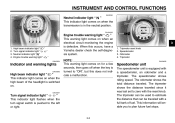
... be used to plan future fuel stops. High beam indicator light " " Turn signal indicator light " " Neutral indicator light " " Engine trouble warning light " " EAU03034 Engine trouble warning light " " This warning light comes on when an electrical circuit monitoring the engine is turned to zero with a full tank of the headlight is in the neutral position. NOTE: This warning light comes on for a few seconds, then goes off when the key is defective. The tripmeter shows...
... be used to plan future fuel stops. High beam indicator light " " Turn signal indicator light " " Neutral indicator light " " Engine trouble warning light " " EAU03034 Engine trouble warning light " " This warning light comes on when an electrical circuit monitoring the engine is turned to zero with a full tank of the headlight is in the neutral position. NOTE: This warning light comes on for a few seconds, then goes off when the key is defective. The tripmeter shows...
Owners Manual
Page 27
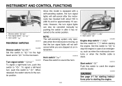
... manually by pushing the switch in case of an emergency, such as when the motorcycle overturns or when the throttle cable is equipped with the starter. When released, the switch returns to crank the engine with a self-canceling system, the turn signal lights will not selfcancel while you are stopped at an intersection. _ _ 1. Set this switch to starting the engine. Engine stop switch " / " Set this switch...
... manually by pushing the switch in case of an emergency, such as when the motorcycle overturns or when the throttle cable is equipped with the starter. When released, the switch returns to crank the engine with a self-canceling system, the turn signal lights will not selfcancel while you are stopped at an intersection. _ _ 1. Set this switch to starting the engine. Engine stop switch " / " Set this switch...
Owners Manual
Page 31
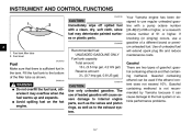
... cloth, since fuel may overflow when the fuel warms up and expands. Fuel tank filler tube 2. EW000130 Recommended fuel: UNLEADED GASOLINE ONLY Fuel tank capacity: Total amount: 16 L (3.5 Imp gal, 4.2 US gal) Reserve amount: 3 L (0.7 Imp gal, 0.8 US gal) ECA00104 Your Yamaha engine has been designed to the fuel system or vehicle performance problems. _ WARNING G Do not overfill the fuel tank, otherwise it may deteriorate painted surfaces or plastic...
... cloth, since fuel may overflow when the fuel warms up and expands. Fuel tank filler tube 2. EW000130 Recommended fuel: UNLEADED GASOLINE ONLY Fuel tank capacity: Total amount: 16 L (3.5 Imp gal, 4.2 US gal) Reserve amount: 3 L (0.7 Imp gal, 0.8 US gal) ECA00104 Your Yamaha engine has been designed to the fuel system or vehicle performance problems. _ WARNING G Do not overfill the fuel tank, otherwise it may deteriorate painted surfaces or plastic...

Owners Manual
Page 39
... the ignition in poor damping performance. Raise the sidestand or lower it may result from improper handling. Luggage strap holder (× 2) EAU01172 Luggage strap holders There is located on each passenger footrest. 3-15 INSTRUMENT AND CONTROL FUNCTIONS EAU00315 EAU00330 3 WARNING This shock absorber contains highly pressurized nitrogen gas. G Do not subject the shock absorber to an open flame or other high heat sources...
... the ignition in poor damping performance. Raise the sidestand or lower it may result from improper handling. Luggage strap holder (× 2) EAU01172 Luggage strap holders There is located on each passenger footrest. 3-15 INSTRUMENT AND CONTROL FUNCTIONS EAU00315 EAU00330 3 WARNING This shock absorber contains highly pressurized nitrogen gas. G Do not subject the shock absorber to an open flame or other high heat sources...

Owners Manual
Page 44
Correct if necessary. and the added safety it inspected and repaired before operating the motorcycle. @ @ 4-2 PAGE 6-27 Wheels and tires 6-17-6-19 Brake and shift pedals Brake and clutch levers Sidestand Chassis fasteners Instruments, lights, signals and switches Sidestand switch • Make sure that operation is smooth. • Lubricate pedal pivoting points if necessary. • Make sure that operation is smooth. • Lubricate lever...
Correct if necessary. and the added safety it inspected and repaired before operating the motorcycle. @ @ 4-2 PAGE 6-27 Wheels and tires 6-17-6-19 Brake and shift pedals Brake and clutch levers Sidestand Chassis fasteners Instruments, lights, signals and switches Sidestand switch • Make sure that operation is smooth. • Lubricate pedal pivoting points if necessary. • Make sure that operation is smooth. • Lubricate lever...
Owners Manual
Page 46
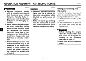
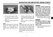
... conditions must be blocked and performance will suffer. Starting and warming up a cold engine In order for any control or function that you do not thoroughly understand. G The transmission is not raised completely, it in gear with all operating controls and their functions before riding. OPERATION AND IMPORTANT RIDING POINTS EAU00373 EAU00376 EAU00372 EAU04219* @ 5 WARNING Become thoroughly familiar with the clutch...
... conditions must be blocked and performance will suffer. Starting and warming up a cold engine In order for any control or function that you do not thoroughly understand. G The transmission is not raised completely, it in gear with all operating controls and their functions before riding. OPERATION AND IMPORTANT RIDING POINTS EAU00373 EAU00376 EAU00372 EAU04219* @ 5 WARNING Become thoroughly familiar with the clutch...
Owners Manual
Page 47
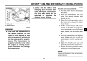
... fuel cock lever to preserve the battery. Each starting , immediately stop switch is set to start, release the start switch. When the engine is cold! _ _ 7. Turn the starter (choke) on when the key is in the neutral position, the neutral indicator light should be on any one attempt. _ _ 6. NOTE: When the transmission is turned to "ON" and make sure that the engine stop the engine, and have a Yamaha dealer check the electrical...
... fuel cock lever to preserve the battery. Each starting , immediately stop switch is set to start, release the start switch. When the engine is cold! _ _ 7. Turn the starter (choke) on when the key is in the neutral position, the neutral indicator light should be on any one attempt. _ _ 6. NOTE: When the transmission is turned to "ON" and make sure that the engine stop the engine, and have a Yamaha dealer check the electrical...
Owners Manual
Page 49
... lubricated only when the engine is running. To start out and accelerate 1. Open the throttle gradually, and at the recommended shift points. @ @ 5 5-4 Shift the transmission into second gear. (Make sure not to shift the transmission into first gear. NOTE: Always shift gears at the same time, release the clutch lever slowly. 4. EAU02988 @ 1. Neutral position EC000048 @ CAUTION: G Even with the engine off, and do not tow the motorcycle for long...
... lubricated only when the engine is running. To start out and accelerate 1. Open the throttle gradually, and at the recommended shift points. @ @ 5 5-4 Shift the transmission into second gear. (Make sure not to shift the transmission into first gear. NOTE: Always shift gears at the same time, release the clutch lever slowly. 4. EAU02988 @ 1. Neutral position EC000048 @ CAUTION: G Even with the engine off, and do not tow the motorcycle for long...

Owners Manual
Page 52
... MINOR REPAIR Periodic maintenance ...6-1 Owner's tool kit ...6-1 Periodic maintenance chart for the emission control system ...6-3 General maintenance and lubrication chart ...6-4 Removing and installing panels ...6-7 Checking the spark plugs ...6-9 Canister (for California only) ...6-11 Engine oil and oil filter element ...6-11 Final gear oil ...6-14 Cleaning the air filter element ...6-15 Adjusting the carburetors ...6-16 Adjusting the throttle cable free play ...6-17 Adjusting the valve clearance ...6-17 Tires ...6-17 Spoke wheels ...6-19 Accessories and replacement...
... MINOR REPAIR Periodic maintenance ...6-1 Owner's tool kit ...6-1 Periodic maintenance chart for the emission control system ...6-3 General maintenance and lubrication chart ...6-4 Removing and installing panels ...6-7 Checking the spark plugs ...6-9 Canister (for California only) ...6-11 Engine oil and oil filter element ...6-11 Final gear oil ...6-14 Cleaning the air filter element ...6-15 Adjusting the carburetors ...6-16 Adjusting the throttle cable free play ...6-17 Adjusting the valve clearance ...6-17 Tires ...6-17 Spoke wheels ...6-19 Accessories and replacement...
Owners Manual
Page 55
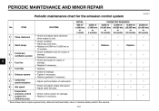
.... • Replace gasket(s) if necessary. • Adjust synchronization of carburetors. • Check and adjust engine idle speed. • Adjust cable free play. • Check control system for the emission control system INITIAL No. PERIODIC MAINTENANCE AND MINOR REPAIR EAU00471 Periodic maintenance chart for damage. • Replace if necessary. 2 Spark plugs √ Replace. √ Replace. √ 3 * Crankcase ventilation system √ √ √ √ √ 6 4 * 5 * 6 * 7 * 8 * Fuel line Fuel filter Exhaust system...
.... • Replace gasket(s) if necessary. • Adjust synchronization of carburetors. • Check and adjust engine idle speed. • Adjust cable free play. • Check control system for the emission control system INITIAL No. PERIODIC MAINTENANCE AND MINOR REPAIR EAU00471 Periodic maintenance chart for damage. • Replace if necessary. 2 Spark plugs √ Replace. √ Replace. √ 3 * Crankcase ventilation system √ √ √ √ √ 6 4 * 5 * 6 * 7 * 8 * Fuel line Fuel filter Exhaust system...

Owners Manual
Page 76
PERIODIC MAINTENANCE AND MINOR REPAIR 1. Turn the adjusting nut while holding the rear brake light switch in direction b. 1. To make the brake light come on just before braking takes effect. Periodically check the brake pedal free play , turn the adjusting nut at the brake pedal end. To make the brake light come on later, turn the adjusting nut in direction a. Rear brake light switch adjusting nut EAU00713 Adjusting the rear brake light switch The rear brake light switch, which...
PERIODIC MAINTENANCE AND MINOR REPAIR 1. Turn the adjusting nut while holding the rear brake light switch in direction b. 1. To make the brake light come on just before braking takes effect. Periodically check the brake pedal free play , turn the adjusting nut at the brake pedal end. To make the brake light come on later, turn the adjusting nut in direction a. Rear brake light switch adjusting nut EAU00713 Adjusting the rear brake light switch The rear brake light switch, which...

Owners Manual
Page 85
... main fuse and the fuse box, which contains the fuses for the individual circuits, are located behind panel B. (See page 6-8 for panel removal and installation procedures.) If a fuse is blown, replace it as follows. 1. Ignition fuse Signaling system fuse Headlight fuse Carburetor heater fuse Spare fuse (× 2) 3. PERIODIC MAINTENANCE AND MINOR REPAIR EC000103 CAUTION: Do not use a fuse of the specified amperage. 1. 2. 3. 4. 5. Fuse box 2. Turn the key to the electrical system and possibly a fire...
... main fuse and the fuse box, which contains the fuses for the individual circuits, are located behind panel B. (See page 6-8 for panel removal and installation procedures.) If a fuse is blown, replace it as follows. 1. Ignition fuse Signaling system fuse Headlight fuse Carburetor heater fuse Spare fuse (× 2) 3. PERIODIC MAINTENANCE AND MINOR REPAIR EC000103 CAUTION: Do not use a fuse of the specified amperage. 1. 2. 3. 4. 5. Fuse box 2. Turn the key to the electrical system and possibly a fire...

Owners Manual
Page 91
... drive shaft. Install the rear wheel, wheel axle, final gear case, and drive shaft by pushing the wheel forward and guiding the drive shaft into the middle gear universal joint. 2. Install the panel. 6. Adjust the brake pedal free play. (See page 6-23 for brake pedal free play adjusting nut onto the brake rod. 4. Bolt (× 4) 2. Middle gear universal joint 2. Drive shaft EAU04353 6 6. NOTE: Make sure to the specified torques. PERIODIC MAINTENANCE...
... drive shaft. Install the rear wheel, wheel axle, final gear case, and drive shaft by pushing the wheel forward and guiding the drive shaft into the middle gear universal joint. 2. Install the panel. 6. Adjust the brake pedal free play. (See page 6-23 for brake pedal free play adjusting nut onto the brake rod. 4. Bolt (× 4) 2. Middle gear universal joint 2. Drive shaft EAU04353 6 6. NOTE: Make sure to the specified torques. PERIODIC MAINTENANCE...

Owners Manual
Page 105
SPECIFICATIONS Bulb voltage, wattage × quantity Headlight Tail/brake light Front turn signal/ position light Rear turn signal light Meter lighting Neutral indicator light High beam indicator light Turn signal indicator light Engine trouble warning light Fuses Main fuse Ignition fuse Signaling system fuse Headlight fuse Carburetor heater fuse 30 A 10 A 10 A 15 A 15 A 12 V, 60/55 W × 1 12 V, 8/27 W × 1 12 V, 27/8 W × 2 12 V, 27 W × 2 12 V, 1.7 W × 1 12 V, 1.7 W × 1 12 V, 1.7 W × 1 12 V, 1.7 W × 1 12 V, 1.7 W × 1 8 8-5
SPECIFICATIONS Bulb voltage, wattage × quantity Headlight Tail/brake light Front turn signal/ position light Rear turn signal light Meter lighting Neutral indicator light High beam indicator light Turn signal indicator light Engine trouble warning light Fuses Main fuse Ignition fuse Signaling system fuse Headlight fuse Carburetor heater fuse 30 A 10 A 10 A 15 A 15 A 12 V, 60/55 W × 1 12 V, 8/27 W × 1 12 V, 27/8 W × 2 12 V, 27 W × 2 12 V, 1.7 W × 1 12 V, 1.7 W × 1 12 V, 1.7 W × 1 12 V, 1.7 W × 1 12 V, 1.7 W × 1 8 8-5

Owners Manual
Page 117
... Maintenance record ...9-5 Model label ...9-2 B Battery ...6-31 Brake and clutch levers, checking and lubricating ...6-28 Brake and shift pedals, checking and lubricating ...6-28 Brake fluid, changing ...6-27 Brake fluid level, checking...6-26 Brake lever...3-5 Brake lever free play, adjusting ...6-22 Brake light switch (rear), adjusting ...6-24 Brake pads and shoes, checking ...6-25 Brake pedal...3-5 Brake pedal position and free play, adjusting ...6-23 F Final gear oil...6-14 Front fork, checking ...6-29 Fuel ...3-7 Fuel cock...3-8 Fuel tank cap...3-6 Fuses, replacing ...6-33 N Neutral...
... Maintenance record ...9-5 Model label ...9-2 B Battery ...6-31 Brake and clutch levers, checking and lubricating ...6-28 Brake and shift pedals, checking and lubricating ...6-28 Brake fluid, changing ...6-27 Brake fluid level, checking...6-26 Brake lever...3-5 Brake lever free play, adjusting ...6-22 Brake light switch (rear), adjusting ...6-24 Brake pads and shoes, checking ...6-25 Brake pedal...3-5 Brake pedal position and free play, adjusting ...6-23 F Final gear oil...6-14 Front fork, checking ...6-29 Fuel ...3-7 Fuel cock...3-8 Fuel tank cap...3-6 Fuses, replacing ...6-33 N Neutral...

Owners Manual
Page 118
...36 V Valve clearance, adjusting ...6-17 Vehicle identification number...9-1 W Warranty, extended...9-9 Warranty limited ...9-7 Wheel bearings, checking ...6-31 Wheel (front) ...6-37 Installing ...6-37 Removing ...6-37 Wheel (rear) ...6-38 Installing ...6-39 Removing ...6-38 Wheels...6-19 T Throttle cable free play, adjusting ...6-17 Throttle grip and cable, checking and lubricating...6-27 Tires ...6-17 Tool kit...6-1 Troubleshooting...6-40 Troubleshooting chart...6-41 Turn signal indicator light ...3-2 Turn signal light or tail/brake light bulb, replacing ...6-35 Turn signal switch...3-3
...36 V Valve clearance, adjusting ...6-17 Vehicle identification number...9-1 W Warranty, extended...9-9 Warranty limited ...9-7 Wheel bearings, checking ...6-31 Wheel (front) ...6-37 Installing ...6-37 Removing ...6-37 Wheel (rear) ...6-38 Installing ...6-39 Removing ...6-38 Wheels...6-19 T Throttle cable free play, adjusting ...6-17 Throttle grip and cable, checking and lubricating...6-27 Tires ...6-17 Tool kit...6-1 Troubleshooting...6-40 Troubleshooting chart...6-41 Turn signal indicator light ...3-2 Turn signal light or tail/brake light bulb, replacing ...6-35 Turn signal switch...3-3