

Owners Manual
Page 12
...steering travel or control operation, or obscure lights or reflectors. 1 1-4 Never install accessories or carry cargo that accessories and cargo are securely attached to the motorcycle before using it does not in mind: 1. Cargo and accessory weight should be kept as low and close to the handlebar, front fork, or front fender. Make sure that would impair the performance... mounting accessories. 1. Carefully inspect the accessory before riding. Shifting weights can create unstable handling or slow steering response. Accessories Genuine Yamaha accessories have been specifically designed...
...steering travel or control operation, or obscure lights or reflectors. 1 1-4 Never install accessories or carry cargo that accessories and cargo are securely attached to the motorcycle before using it does not in mind: 1. Cargo and accessory weight should be kept as low and close to the handlebar, front fork, or front fender. Make sure that would impair the performance... mounting accessories. 1. Carefully inspect the accessory before riding. Shifting weights can create unstable handling or slow steering response. Accessories Genuine Yamaha accessories have been specifically designed...
Owners Manual
Page 13
... passing or being passed by large vehicles. Never refuel while smoking or in the vicinity of time in an area that has adequate ventilation. 3. c. When parking the motorcycle, note the following: 1-5 b. Never start the engine or let it run for any gasoline on the engine or exhaust system when refueling. Accessories fitted to spill any length of an open flame. c. 2.
... passing or being passed by large vehicles. Never refuel while smoking or in the vicinity of time in an area that has adequate ventilation. 3. c. When parking the motorcycle, note the following: 1-5 b. Never start the engine or let it run for any gasoline on the engine or exhaust system when refueling. Accessories fitted to spill any length of an open flame. c. 2.

Owners Manual
Page 24
INSTRUMENT AND CONTROL FUNCTIONS Main switch/steering lock ...3-1 Indicator and warning lights ...3-2 Speedometer unit ...3-2 Handlebar switches ...3-3 Clutch lever ...3-4 Shift pedal (XVS650)...3-4 Shift pedal (XVS650A) ...3-4 Brake lever ...3-5 Brake pedal ...3-5 Fuel tank cap ...3-6 Fuel ...3-7 Fuel cock ...3-8 Starter (choke) knob ...3-9 Seats (XVS650) ...3-9 Seats (XVS650A) ...3-11 Helmet holder ...3-12 Storage compartment ...3-13 Adjusting the shock absorber assembly ...3-14 Luggage strap holders ...3-15 Sidestand ...3-15 Ignition circuit cut-off system ...3-16 3
INSTRUMENT AND CONTROL FUNCTIONS Main switch/steering lock ...3-1 Indicator and warning lights ...3-2 Speedometer unit ...3-2 Handlebar switches ...3-3 Clutch lever ...3-4 Shift pedal (XVS650)...3-4 Shift pedal (XVS650A) ...3-4 Brake lever ...3-5 Brake pedal ...3-5 Fuel tank cap ...3-6 Fuel ...3-7 Fuel cock ...3-8 Starter (choke) knob ...3-9 Seats (XVS650) ...3-9 Seats (XVS650A) ...3-11 Helmet holder ...3-12 Storage compartment ...3-13 Adjusting the shock absorber assembly ...3-14 Luggage strap holders ...3-15 Sidestand ...3-15 Ignition circuit cut-off system ...3-16 3

Owners Manual
Page 25
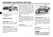
... . The key cannot be removed. The various positions are off . To lock the steering 1. Turn. EW000016 EAU00029 EAU00040 Main switch/steering lock The main switch/steering lock controls the ignition and lighting systems, and is locked, and all the way to "OFF" or "LOCK". @ @ OFF All electrical systems are supplied with power, the headlight, meter lighting, taillight and front position lights come on, and the engine can be removed. INSTRUMENT AND CONTROL FUNCTIONS...
... . The key cannot be removed. The various positions are off . To lock the steering 1. Turn. EW000016 EAU00029 EAU00040 Main switch/steering lock The main switch/steering lock controls the ignition and lighting systems, and is locked, and all the way to "OFF" or "LOCK". @ @ OFF All electrical systems are supplied with power, the headlight, meter lighting, taillight and front position lights come on, and the engine can be removed. INSTRUMENT AND CONTROL FUNCTIONS...
Owners Manual
Page 26
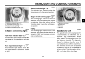
... tank of the headlight is switched on for a few seconds, then goes off when the key is turned to plan future fuel stops. The tripmeter shows the distance traveled since it was last set to the left or right. 3-2 INSTRUMENT AND CONTROL FUNCTIONS EAU00061 Neutral indicator light " " This indicator light comes on when an electrical circuit monitoring the engine is defective. NOTE: This warning light...
... tank of the headlight is switched on for a few seconds, then goes off when the key is turned to plan future fuel stops. The tripmeter shows the distance traveled since it was last set to the left or right. 3-2 INSTRUMENT AND CONTROL FUNCTIONS EAU00061 Neutral indicator light " " This indicator light comes on when an electrical circuit monitoring the engine is defective. NOTE: This warning light...
Owners Manual
Page 27
... released, the switch returns to " ". Start switch " " / " EAU03890 EAU00129 Turn signal switch " / " To signal a right-hand turn signal lights can also be canceled manually by pushing the switch in case of an emergency, such as when the motorcycle overturns or when the throttle cable is stuck. EC000005 CAUTION: See page 5-1 for the low beam. Turn signal switch " 3. However, the turn , push this switch to starting instructions prior to " ". INSTRUMENT AND CONTROL FUNCTIONS...
... released, the switch returns to " ". Start switch " " / " EAU03890 EAU00129 Turn signal switch " / " To signal a right-hand turn signal lights can also be canceled manually by pushing the switch in case of an emergency, such as when the motorcycle overturns or when the throttle cable is stuck. EC000005 CAUTION: See page 5-1 for the low beam. Turn signal switch " 3. However, the turn , push this switch to starting instructions prior to " ". INSTRUMENT AND CONTROL FUNCTIONS...
Owners Manual
Page 31
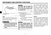
... vehicle performance problems. _ WARNING G Do not overfill the fuel tank, otherwise it can be used if the ethanol content does not exceed 10%. The use regular unleaded gasoline with a clean, dry, soft cloth, since fuel may overflow when the fuel warms up and expands. Use of leaded gasoline will extend spark plug life and reduce maintenance costs. G Avoid spilling fuel on the hot engine...
... vehicle performance problems. _ WARNING G Do not overfill the fuel tank, otherwise it can be used if the ethanol content does not exceed 10%. The use regular unleaded gasoline with a clean, dry, soft cloth, since fuel may overflow when the fuel warms up and expands. Use of leaded gasoline will extend spark plug life and reduce maintenance costs. G Avoid spilling fuel on the hot engine...

Owners Manual
Page 39
... heat sources, otherwise it with or attempt to excessive gas pressure. G Always have a Yamaha dealer service the shock absorber. @ @ Sidestand The sidestand is located on each passenger footrest. 3-15 NOTE: The built-in sidestand switch is a luggage strap holder on the left side of the ignition circuit cut -off system.) @ @ 1. G Do not subject the shock absorber to an open the gas cylinder...
... heat sources, otherwise it with or attempt to excessive gas pressure. G Always have a Yamaha dealer service the shock absorber. @ @ Sidestand The sidestand is located on each passenger footrest. 3-15 NOTE: The built-in sidestand switch is a luggage strap holder on the left side of the ignition circuit cut -off system.) @ @ 1. G Do not subject the shock absorber to an open the gas cylinder...

Owners Manual
Page 44
PAGE 6-27 Wheels and tires 6-17-6-19 Brake and shift pedals Brake and clutch levers Sidestand Chassis fasteners Instruments, lights, signals and switches Sidestand switch • Make sure that operation is ...repaired before operating the motorcycle. @ @ 4-2 PRE-OPERATION CHECKS ITEM Control cables CHECKS • Make sure that all nuts, bolts and screws are properly tightened. • Tighten if necessary. • Check operation. • Correct if necessary. • Check operation of ignition circuit cut-off system. • If system is defective, have Yamaha dealer check vehicle...
PAGE 6-27 Wheels and tires 6-17-6-19 Brake and shift pedals Brake and clutch levers Sidestand Chassis fasteners Instruments, lights, signals and switches Sidestand switch • Make sure that operation is ...repaired before operating the motorcycle. @ @ 4-2 PRE-OPERATION CHECKS ITEM Control cables CHECKS • Make sure that all nuts, bolts and screws are properly tightened. • Tighten if necessary. • Check operation. • Correct if necessary. • Check operation of ignition circuit cut-off system. • If system is defective, have Yamaha dealer check vehicle...
Owners Manual
Page 46
... conditions must be blocked and performance will be met: G The transmission is not raised completely, it in gear with the clutch lever pulled and the sidestand up . Always make sure that you do not thoroughly understand. 5- EW000054 @ _ WARNING Before starting out, make sure that there is up . G _ @ 5-1 G Before starting the engine, check the function of time. Consult a Yamaha dealer regarding any length...
... conditions must be blocked and performance will be met: G The transmission is not raised completely, it in gear with the clutch lever pulled and the sidestand up . Always make sure that you do not thoroughly understand. 5- EW000054 @ _ WARNING Before starting out, make sure that there is up . G _ @ 5-1 G Before starting the engine, check the function of time. Consult a Yamaha dealer regarding any length...
Owners Manual
Page 47
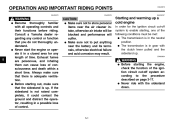
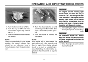
.... _ 1. Shift the transmission into the neutral position. Each starting off. Never accelerate hard when the engine is set to " ". 3. Start the engine by pushing the start switch, wait a few seconds. After starting the engine, move the starter (choke) knob back halfway. NOTE: If the engine fails to start, release the start switch. OPERATION AND IMPORTANT RIDING POINTS ECA00101 CAUTION: The engine trouble warning light should come on when the key is turned...
.... _ 1. Shift the transmission into the neutral position. Each starting off. Never accelerate hard when the engine is set to " ". 3. Start the engine by pushing the start switch, wait a few seconds. After starting the engine, move the starter (choke) knob back halfway. NOTE: If the engine fails to start, release the start switch. OPERATION AND IMPORTANT RIDING POINTS ECA00101 CAUTION: The engine trouble warning light should come on when the key is turned...

Owners Manual
Page 49
... the throttle part way and gradually release the clutch lever. 7. NOTE: Always shift gears at the same time, release the clutch lever slowly. 4. OPERATION AND IMPORTANT RIDING POINTS XVS650A G Always use the clutch while changing gears to avoid damaging the engine, transmission, and drive train, which are not designed to withstand the shock of time with the transmission in . 5. Shift the transmission into second gear. (Make sure not to shift the transmission...
... the throttle part way and gradually release the clutch lever. 7. NOTE: Always shift gears at the same time, release the clutch lever slowly. 4. OPERATION AND IMPORTANT RIDING POINTS XVS650A G Always use the clutch while changing gears to avoid damaging the engine, transmission, and drive train, which are not designed to withstand the shock of time with the transmission in . 5. Shift the transmission into second gear. (Make sure not to shift the transmission...
Owners Manual
Page 52
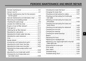
... MINOR REPAIR Periodic maintenance ...6-1 Owner's tool kit ...6-1 Periodic maintenance chart for the emission control system ...6-3 General maintenance and lubrication chart ...6-4 Removing and installing panels ...6-7 Checking the spark plugs ...6-9 Canister (for California only) ...6-11 Engine oil and oil filter element ...6-11 Final gear oil ...6-14 Cleaning the air filter element ...6-15 Adjusting the carburetors ...6-16 Adjusting the throttle cable free play ...6-17 Adjusting the valve clearance ...6-17 Tires ...6-17 Spoke wheels ...6-19 Accessories and replacement...
... MINOR REPAIR Periodic maintenance ...6-1 Owner's tool kit ...6-1 Periodic maintenance chart for the emission control system ...6-3 General maintenance and lubrication chart ...6-4 Removing and installing panels ...6-7 Checking the spark plugs ...6-9 Canister (for California only) ...6-11 Engine oil and oil filter element ...6-11 Final gear oil ...6-14 Cleaning the air filter element ...6-15 Adjusting the carburetors ...6-16 Adjusting the throttle cable free play ...6-17 Adjusting the valve clearance ...6-17 Tires ...6-17 Spoke wheels ...6-19 Accessories and replacement...
Owners Manual
Page 55
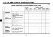
PERIODIC MAINTENANCE AND MINOR REPAIR EAU00471 Periodic maintenance chart for damage. • Replace if necessary. 2 Spark plugs √ Replace. √ Replace. √ 3 * Crankcase ventilation system √ √ √ √ √ 6 4 * 5 * 6 * 7 * 8 * Fuel line Fuel filter Exhaust system Carburetor synchronization Idle speed Evaporative emission control system (For California only) √ √ √ √ √ √ √ √ √ √ √ √ √ √ √ √ √ √ 9 * √...
PERIODIC MAINTENANCE AND MINOR REPAIR EAU00471 Periodic maintenance chart for damage. • Replace if necessary. 2 Spark plugs √ Replace. √ Replace. √ 3 * Crankcase ventilation system √ √ √ √ √ 6 4 * 5 * 6 * 7 * 8 * Fuel line Fuel filter Exhaust system Carburetor synchronization Idle speed Evaporative emission control system (For California only) √ √ √ √ √ √ √ √ √ √ √ √ √ √ √ √ √ √ 9 * √...

Owners Manual
Page 76
... a. Rear brake light switch adjusting nut EAU00713 Adjusting the rear brake light switch The rear brake light switch, which is activated by the brake pedal, is properly adjusted when the brake light comes on earlier, turn the adjusting nut at the brake pedal end. To decrease the brake pedal free play and, if necessary, adjust it as follows. PERIODIC MAINTENANCE AND MINOR REPAIR 1. Turn the adjusting nut while holding the rear brake light switch in...
... a. Rear brake light switch adjusting nut EAU00713 Adjusting the rear brake light switch The rear brake light switch, which is activated by the brake pedal, is properly adjusted when the brake light comes on earlier, turn the adjusting nut at the brake pedal end. To decrease the brake pedal free play and, if necessary, adjust it as follows. PERIODIC MAINTENANCE AND MINOR REPAIR 1. Turn the adjusting nut while holding the rear brake light switch in...

Owners Manual
Page 85
... turn off the electrical circuit in question to check if the device operates. 4. Fuse box 2. Main fuse 3. Ignition fuse Signaling system fuse Headlight fuse Carburetor heater fuse Spare fuse (× 2) 3. Spare main fuse EAU04190* Replacing the fuses 6 The main fuse and the fuse box, which contains the fuses for the individual circuits, are located behind panel B. (See page 6-8 for panel removal and installation procedures.) If a fuse is blown, replace it as follows. 1. PERIODIC MAINTENANCE...
... turn off the electrical circuit in question to check if the device operates. 4. Fuse box 2. Main fuse 3. Ignition fuse Signaling system fuse Headlight fuse Carburetor heater fuse Spare fuse (× 2) 3. Spare main fuse EAU04190* Replacing the fuses 6 The main fuse and the fuse box, which contains the fuses for the individual circuits, are located behind panel B. (See page 6-8 for panel removal and installation procedures.) If a fuse is blown, replace it as follows. 1. PERIODIC MAINTENANCE...

Owners Manual
Page 91
... guiding the drive shaft into the middle gear universal joint. 2. While supporting the drive shaft, pull the rear wheel back to support the drive shaft as an assembly: wheel, wheel axle, final gear case, and drive shaft. Install the panel. 6. PERIODIC MAINTENANCE AND MINOR REPAIR 3. Install the brake rod onto the brake camshaft lever, and then install the brake pedal free play adjustment procedures.) 1. Tighten the axle nut, the final gear case bolts...
... guiding the drive shaft into the middle gear universal joint. 2. While supporting the drive shaft, pull the rear wheel back to support the drive shaft as an assembly: wheel, wheel axle, final gear case, and drive shaft. Install the panel. 6. PERIODIC MAINTENANCE AND MINOR REPAIR 3. Install the brake rod onto the brake camshaft lever, and then install the brake pedal free play adjustment procedures.) 1. Tighten the axle nut, the final gear case bolts...

Owners Manual
Page 105
SPECIFICATIONS Bulb voltage, wattage × quantity Headlight Tail/brake light Front turn signal/ position light Rear turn signal light Meter lighting Neutral indicator light High beam indicator light Turn signal indicator light Engine trouble warning light Fuses Main fuse Ignition fuse Signaling system fuse Headlight fuse Carburetor heater fuse 30 A 10 A 10 A 15 A 15 A 12 V, 60/55 W × 1 12 V, 8/27 W × 1 12 V, 27/8 W × 2 12 V, 27 W × 2 12 V, 1.7 W × 1 12 V, 1.7 W × 1 12 V, 1.7 W × 1 12 V, 1.7 W × 1 12 V, 1.7 W × 1 8 8-5
SPECIFICATIONS Bulb voltage, wattage × quantity Headlight Tail/brake light Front turn signal/ position light Rear turn signal light Meter lighting Neutral indicator light High beam indicator light Turn signal indicator light Engine trouble warning light Fuses Main fuse Ignition fuse Signaling system fuse Headlight fuse Carburetor heater fuse 30 A 10 A 10 A 15 A 15 A 12 V, 60/55 W × 1 12 V, 8/27 W × 1 12 V, 27/8 W × 2 12 V, 27 W × 2 12 V, 1.7 W × 1 12 V, 1.7 W × 1 12 V, 1.7 W × 1 12 V, 1.7 W × 1 12 V, 1.7 W × 1 8 8-5

Owners Manual
Page 117
... Maintenance record ...9-5 Model label ...9-2 B Battery ...6-31 Brake and clutch levers, checking and lubricating ...6-28 Brake and shift pedals, checking and lubricating ...6-28 Brake fluid, changing ...6-27 Brake fluid level, checking...6-26 Brake lever...3-5 Brake lever free play, adjusting ...6-22 Brake light switch (rear), adjusting ...6-24 Brake pads and shoes, checking ...6-25 Brake pedal...3-5 Brake pedal position and free play, adjusting ...6-23 F Final gear oil...6-14 Front fork, checking ...6-29 Fuel ...3-7 Fuel cock...3-8 Fuel tank cap...3-6 Fuses, replacing ...6-33 N Neutral...
... Maintenance record ...9-5 Model label ...9-2 B Battery ...6-31 Brake and clutch levers, checking and lubricating ...6-28 Brake and shift pedals, checking and lubricating ...6-28 Brake fluid, changing ...6-27 Brake fluid level, checking...6-26 Brake lever...3-5 Brake lever free play, adjusting ...6-22 Brake light switch (rear), adjusting ...6-24 Brake pads and shoes, checking ...6-25 Brake pedal...3-5 Brake pedal position and free play, adjusting ...6-23 F Final gear oil...6-14 Front fork, checking ...6-29 Fuel ...3-7 Fuel cock...3-8 Fuel tank cap...3-6 Fuses, replacing ...6-33 N Neutral...

Owners Manual
Page 118
...36 V Valve clearance, adjusting ...6-17 Vehicle identification number...9-1 W Warranty, extended...9-9 Warranty limited ...9-7 Wheel bearings, checking ...6-31 Wheel (front) ...6-37 Installing ...6-37 Removing ...6-37 Wheel (rear) ...6-38 Installing ...6-39 Removing ...6-38 Wheels...6-19 T Throttle cable free play, adjusting ...6-17 Throttle grip and cable, checking and lubricating...6-27 Tires ...6-17 Tool kit...6-1 Troubleshooting...6-40 Troubleshooting chart...6-41 Turn signal indicator light ...3-2 Turn signal light or tail/brake light bulb, replacing ...6-35 Turn signal switch...3-3
...36 V Valve clearance, adjusting ...6-17 Vehicle identification number...9-1 W Warranty, extended...9-9 Warranty limited ...9-7 Wheel bearings, checking ...6-31 Wheel (front) ...6-37 Installing ...6-37 Removing ...6-37 Wheel (rear) ...6-38 Installing ...6-39 Removing ...6-38 Wheels...6-19 T Throttle cable free play, adjusting ...6-17 Throttle grip and cable, checking and lubricating...6-27 Tires ...6-17 Tool kit...6-1 Troubleshooting...6-40 Troubleshooting chart...6-41 Turn signal indicator light ...3-2 Turn signal light or tail/brake light bulb, replacing ...6-35 Turn signal switch...3-3