
Owners Manual
Page 12
..., front fork, or front fender. Accessories Genuine Yamaha accessories have been specifically designed for the proper selection, installation and use on both sides of non-Yamaha accessories. Keep the following in any way reduce ground clearance or cornering clearance, limit suspension travel, steering travel or control operation, or obscure lights or reflectors. 1 1-4 Shifting weights can create unstable handling or slow steering response. Use extreme caution when...
..., front fork, or front fender. Accessories Genuine Yamaha accessories have been specifically designed for the proper selection, installation and use on both sides of non-Yamaha accessories. Keep the following in any way reduce ground clearance or cornering clearance, limit suspension travel, steering travel or control operation, or obscure lights or reflectors. 1 1-4 Shifting weights can create unstable handling or slow steering response. Use extreme caution when...
Owners Manual
Page 13
... any length of lights or engine power. 1 Gasoline and exhaust gas 1. SAFETY INFORMATION a. If accessories are added to the handlebar or front fork area, they must be as lightweight as possible and should be kept to improper weight distribution or aerodynamic changes. Wind may seriously affect the stability of an open flame. 2. c. If electrical accessories exceed the capacity of the motorcycle's electrical system, an electric...
... any length of lights or engine power. 1 Gasoline and exhaust gas 1. SAFETY INFORMATION a. If accessories are added to the handlebar or front fork area, they must be as lightweight as possible and should be kept to improper weight distribution or aerodynamic changes. Wind may seriously affect the stability of an open flame. 2. c. If electrical accessories exceed the capacity of the motorcycle's electrical system, an electric...
Owners Manual
Page 23
INSTRUMENT AND CONTROL FUNCTIONS Main switch/steering lock ...3-1 Indicator and warning lights ...3-2 Speedometer unit ...3-3 Handlebar switches ...3-3 Clutch lever ...3-4 Shift pedal (XVS1100)...3-5 Shift pedal (XVS1100A) ...3-5 Brake lever ...3-5 Brake pedal ...3-6 Fuel tank cap ...3-7 Fuel ...3-7 Fuel cock ...3-9 Starter (choke) lever ...3-10 Seats (XVS1100) ...3-11 Seats (XVS1100A) ...3-12 Helmet holder ...3-13 Storage compartment ...3-14 Adjusting the shock absorber assembly ...3-15 Luggage strap holders ...3-18 Sidestand ...3-19 Ignition circuit cut-off system ...3-19 3
INSTRUMENT AND CONTROL FUNCTIONS Main switch/steering lock ...3-1 Indicator and warning lights ...3-2 Speedometer unit ...3-3 Handlebar switches ...3-3 Clutch lever ...3-4 Shift pedal (XVS1100)...3-5 Shift pedal (XVS1100A) ...3-5 Brake lever ...3-5 Brake pedal ...3-6 Fuel tank cap ...3-7 Fuel ...3-7 Fuel cock ...3-9 Starter (choke) lever ...3-10 Seats (XVS1100) ...3-11 Seats (XVS1100A) ...3-12 Helmet holder ...3-13 Storage compartment ...3-14 Adjusting the shock absorber assembly ...3-15 Luggage strap holders ...3-18 Sidestand ...3-19 Ignition circuit cut-off system ...3-19 3
Owners Manual
Page 24
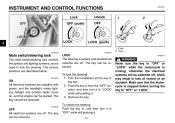
... of control or an accident. Turn. EAU00032 LOCK The steering is locked, and all the way to "OFF" or "LOCK" while the motorcycle is stopped before turning the key to "OFF" while still pushing it to "OFF" or "LOCK". _ _ OFF All electrical systems are supplied with power, and the headlight, meter lighting, taillight and position lights come on, and the engine can be started. The key can...
... of control or an accident. Turn. EAU00032 LOCK The steering is locked, and all the way to "OFF" or "LOCK" while the motorcycle is stopped before turning the key to "OFF" while still pushing it to "OFF" or "LOCK". _ _ OFF All electrical systems are supplied with power, and the headlight, meter lighting, taillight and position lights come on, and the engine can be started. The key can...
Owners Manual
Page 25
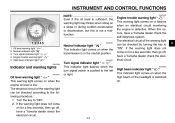
... a Yamaha dealer check the self-diagnosis system. EAU00057 Engine trouble warning light " " This warning light comes on when the engine oil level is low. When this is defective. Oil level warning light " " This warning light comes on or flashes when an electrical circuit monitoring the engine is not a malfunction. _ _ EAU04585 EAU00061 1. 2. 3. 4. 5. The electrical circuit of the headlight is switched on. Oil level warning light " " Neutral indicator light " " Turn signal indicator light " " Engine trouble warning light " " High beam indicator light...
... a Yamaha dealer check the self-diagnosis system. EAU00057 Engine trouble warning light " " This warning light comes on when the engine oil level is low. When this is defective. Oil level warning light " " This warning light comes on or flashes when an electrical circuit monitoring the engine is not a malfunction. _ _ EAU04585 EAU00061 1. 2. 3. 4. 5. The electrical circuit of the headlight is switched on. Oil level warning light " " Neutral indicator light " " Turn signal indicator light " " Engine trouble warning light " " High beam indicator light...
Owners Manual
Page 27
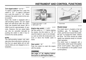
... with the starter. Set this switch to " ". Engine stop switch " / " Set this switch to " ". To engage the clutch, release the lever. Start switch " " / " EAU03890 1. To signal a left handlebar grip. INSTRUMENT AND CONTROL FUNCTIONS EAU04218 Turn signal switch " / " To signal a right-hand turn, push this switch to " " before starting the engine. _ _ 3-4 To disengage the clutch, pull the lever toward the handlebar grip. The lever should be canceled manually by pushing the switch in case...
... with the starter. Set this switch to " ". Engine stop switch " / " Set this switch to " ". To engage the clutch, release the lever. Start switch " " / " EAU03890 1. To signal a left handlebar grip. INSTRUMENT AND CONTROL FUNCTIONS EAU04218 Turn signal switch " / " To signal a right-hand turn, push this switch to " " before starting the engine. _ _ 3-4 To disengage the clutch, pull the lever toward the handlebar grip. The lever should be canceled manually by pushing the switch in case...
Owners Manual
Page 42
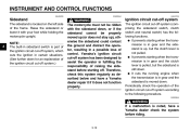
... of control. G It cuts the running engine when the transmission is in gear and the sidestand is part of the ignition circuit cut-off system, which cuts the ignition in sidestand switch is moved down for an explanation of the ignition circuit cut -off system (comprising the sidestand switch, clutch switch and neutral switch) has the following procedure. Yamaha's ignition circuit cut -off system.) _ _ WARNING The...
... of control. G It cuts the running engine when the transmission is in gear and the sidestand is part of the ignition circuit cut-off system, which cuts the ignition in sidestand switch is moved down for an explanation of the ignition circuit cut -off system (comprising the sidestand switch, clutch switch and neutral switch) has the following procedure. Yamaha's ignition circuit cut -off system.) _ _ WARNING The...
Owners Manual
Page 46
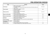
...Check air pressure. PAGE 6-15, 6-24 Control cables 6-24 Wheels and tires 6-15-6-17 Brake and shift pedals Brake and clutch levers Sidestand Chassis fasteners Instruments, lights, signals and switches Sidestand switch •...ignition circuit cut-off system. • If system is smooth. • Lubricate if necessary Check for damage. Correct if necessary. PRE-OPERATION CHECKS ITEM Throttle grip CHECKS • Make sure that operation is smooth. • Check cable free play. • If necessary, have Yamaha dealer check vehicle. 6-25 6-25 6-25 - - 3-20 4 4-2 Check tire condition...
...Check air pressure. PAGE 6-15, 6-24 Control cables 6-24 Wheels and tires 6-15-6-17 Brake and shift pedals Brake and clutch levers Sidestand Chassis fasteners Instruments, lights, signals and switches Sidestand switch •...ignition circuit cut-off system. • If system is smooth. • Lubricate if necessary Check for damage. Correct if necessary. PRE-OPERATION CHECKS ITEM Throttle grip CHECKS • Make sure that operation is smooth. • Check cable free play. • If necessary, have Yamaha dealer check vehicle. 6-25 6-25 6-25 - - 3-20 4 4-2 Check tire condition...
Owners Manual
Page 49
... and performance will suffer. Starting and warming up a cold engine In order for any control or function that there is not raised completely, it in a possible loss of time. G _ _ 5-1 G _ CAUTION: G Make sure not to the procedure described on page 3-20. EW000054 _ _ WARNING Before starting out, make sure that you do not thoroughly understand. G The transmission is in gear with the clutch...
... and performance will suffer. Starting and warming up a cold engine In order for any control or function that there is not raised completely, it in a possible loss of time. G _ _ 5-1 G _ CAUTION: G Make sure not to the procedure described on page 3-20. EW000054 _ _ WARNING Before starting out, make sure that you do not thoroughly understand. G The transmission is in gear with the clutch...
Owners Manual
Page 50
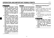
... oil level warning light flickers or remains on after starting the engine, have a Yamaha dealer check the electrical circuit. OPERATION AND IMPORTANT RIDING POINTS ECA00103 _ 1. Turn the key to "ON" and make sure that the engine stop the engine, and then check the engine oil level and the vehicle for starter (choke) operation.) 5. NOTE: When the transmission is set to preserve the battery. Do not crank the engine...
... oil level warning light flickers or remains on after starting the engine, have a Yamaha dealer check the electrical circuit. OPERATION AND IMPORTANT RIDING POINTS ECA00103 _ 1. Turn the key to "ON" and make sure that the engine stop the engine, and then check the engine oil level and the vehicle for starter (choke) operation.) 5. NOTE: When the transmission is set to preserve the battery. Do not crank the engine...
Owners Manual
Page 52
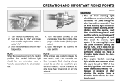
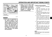
... light should go out. 3. NOTE: Always shift gears at the same time, release the clutch lever slowly. 4. Open the throttle part way and gradually release the clutch lever. 7. Open the throttle gradually, and at the recommended shift points. _ _ 5 5-4 OPERATION AND IMPORTANT RIDING POINTS XVS1100A G Always use the clutch while changing gears to avoid damaging the engine, transmission, and drive train, which are not designed to withstand the shock...
... light should go out. 3. NOTE: Always shift gears at the same time, release the clutch lever slowly. 4. Open the throttle part way and gradually release the clutch lever. 7. Open the throttle gradually, and at the recommended shift points. _ _ 5 5-4 OPERATION AND IMPORTANT RIDING POINTS XVS1100A G Always use the clutch while changing gears to avoid damaging the engine, transmission, and drive train, which are not designed to withstand the shock...
Owners Manual
Page 55
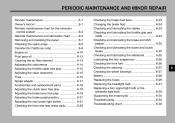
PERIODIC MAINTENANCE AND MINOR REPAIR Periodic maintenance ...6-1 Owner's tool kit ...6-1 Periodic maintenance chart for the emission control system ...6-3 General maintenance and lubrication chart ...6-4 Removing and installing the panel ...6-7 Checking the spark plugs ...6-8 Canister (for California only) ...6-9 Engine oil ...6-10 Final gear oil ...6-12 Cleaning the air filter element ...6-13 Adjusting the carburetors ...6-14 Adjusting the throttle cable free play ...6-15 Adjusting the valve clearance ...6-15 Tires ...6-15 Spoke wheels ...6-17 Accessories and replacement parts...
PERIODIC MAINTENANCE AND MINOR REPAIR Periodic maintenance ...6-1 Owner's tool kit ...6-1 Periodic maintenance chart for the emission control system ...6-3 General maintenance and lubrication chart ...6-4 Removing and installing the panel ...6-7 Checking the spark plugs ...6-8 Canister (for California only) ...6-9 Engine oil ...6-10 Final gear oil ...6-12 Cleaning the air filter element ...6-13 Adjusting the carburetors ...6-14 Adjusting the throttle cable free play ...6-15 Adjusting the valve clearance ...6-15 Tires ...6-15 Spoke wheels ...6-17 Accessories and replacement parts...
Owners Manual
Page 58
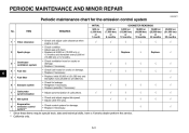
...; Replace gasket(s) if necessary. • Adjust synchronization of carburetors. • Check and adjust engine idle speed. • Adjust cable free play. • Check control system for the emission control system INITIAL No. PERIODIC MAINTENANCE AND MINOR REPAIR EAU00471 Periodic maintenance chart for damage. • Replace if necessary. √ √ √ √ √ √ 2 Spark plugs √ Replace. √ Replace. √ 3 * 4 * 5 * 6 * 7 * 8 * 9 * Crankcase ventilation system Fuel line Fuel filter √...
...; Replace gasket(s) if necessary. • Adjust synchronization of carburetors. • Check and adjust engine idle speed. • Adjust cable free play. • Check control system for the emission control system INITIAL No. PERIODIC MAINTENANCE AND MINOR REPAIR EAU00471 Periodic maintenance chart for damage. • Replace if necessary. √ √ √ √ √ √ 2 Spark plugs √ Replace. √ Replace. √ 3 * 4 * 5 * 6 * 7 * 8 * 9 * Crankcase ventilation system Fuel line Fuel filter √...
Owners Manual
Page 64
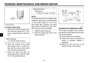
.... Place the spark plug cover in ) 2. PERIODIC MAINTENANCE AND MINOR REPAIR Tightening torque: Spark plug: 20 Nm (2.0 m·kgf, 14.5 ft·lbf) NOTE: If a torque wrench is not available when installing a spark plug, a good estimate of the spark plug gasket and its mating surface, and then wipe off any grime from the spark plug threads. 3. However, the spark plug should be tightened to specification. Clean it...
.... Place the spark plug cover in ) 2. PERIODIC MAINTENANCE AND MINOR REPAIR Tightening torque: Spark plug: 20 Nm (2.0 m·kgf, 14.5 ft·lbf) NOTE: If a torque wrench is not available when installing a spark plug, a good estimate of the spark plug gasket and its mating surface, and then wipe off any grime from the spark plug threads. 3. However, the spark plug should be tightened to specification. Clean it...
Owners Manual
Page 71
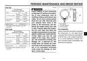
... several characteristics of an overloaded motorcycle could cause tire damage, an accident, or even injury. _ 1. Make sure that can shift. Tire sidewall 2. PERIODIC MAINTENANCE AND MINOR REPAIR XVS1100 Tire air pressure (measured on cold tires) Load* Up to side. maximum Maximum load* * Total weight of rider, passenger, cargo and accessories WARNING Proper loading of your motorcycle is cracked, contact a Yamaha dealer immediately and have the...
... several characteristics of an overloaded motorcycle could cause tire damage, an accident, or even injury. _ 1. Make sure that can shift. Tire sidewall 2. PERIODIC MAINTENANCE AND MINOR REPAIR XVS1100 Tire air pressure (measured on cold tires) Load* Up to side. maximum Maximum load* * Total weight of rider, passenger, cargo and accessories WARNING Proper loading of your motorcycle is cracked, contact a Yamaha dealer immediately and have the...
Owners Manual
Page 76
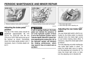
... operating the motorcycle. PERIODIC MAINTENANCE AND MINOR REPAIR XVS1100 XVS1100A a. Turn the adjusting nut while holding the rear brake light switch in the hydraulic system, have a Yamaha dealer adjust it. If necessary, adjust the brake light switch as shown. Distance between brake pedal and footrest EW000109 1. Distance between brake pedal and footrest EAU01746* a. Rear brake light switch 2. Air in the hydraulic system will diminish the braking performance, which may result...
... operating the motorcycle. PERIODIC MAINTENANCE AND MINOR REPAIR XVS1100 XVS1100A a. Turn the adjusting nut while holding the rear brake light switch in the hydraulic system, have a Yamaha dealer adjust it. If necessary, adjust the brake light switch as shown. Distance between brake pedal and footrest EW000109 1. Distance between brake pedal and footrest EAU01746* a. Rear brake light switch 2. Air in the hydraulic system will diminish the braking performance, which may result...
Owners Manual
Page 84
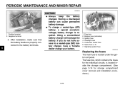
... battery. 1. 2. 3. 4. 5. 6. 7. Fuse box Backup fuse (odometer) Ignition fuse Headlight fuse Carburetor heater fuse Spare fuse (× 3) Signaling system fuse EAU04210 Replacing the fuses The main fuse is located inside the storage compartment. (See page 3-14 for the individual circuits, is located under the ignitor unit panel. The fuse box, which contains the fuses for storage compartment cover removal and installation procedures.) 6-29 Using a conventional battery charger will damage the battery. PERIODIC MAINTENANCE...
... battery. 1. 2. 3. 4. 5. 6. 7. Fuse box Backup fuse (odometer) Ignition fuse Headlight fuse Carburetor heater fuse Spare fuse (× 3) Signaling system fuse EAU04210 Replacing the fuses The main fuse is located inside the storage compartment. (See page 3-14 for the individual circuits, is located under the ignitor unit panel. The fuse box, which contains the fuses for storage compartment cover removal and installation procedures.) 6-29 Using a conventional battery charger will damage the battery. PERIODIC MAINTENANCE...
Owners Manual
Page 85
... question to the electrical system and possibly a fire. _ _ 1. Turn the key to the right. 4. Spare main fuse 3. Pull the ignitor unit panel outward to "ON" and turn off the electrical circuit in with a screwdriver, then pulling the fastener out. 3. PERIODIC MAINTENANCE AND MINOR REPAIR EC000103 CAUTION: Do not use a fuse of the specified amperage. Specified fuses: Main fuse: Backup fuse (odometer): Ignition fuse: Headlight fuse: Carburetor heater fuse: Signaling system fuse: 6-30 6.
... question to the electrical system and possibly a fire. _ _ 1. Turn the key to the right. 4. Spare main fuse 3. Pull the ignitor unit panel outward to "ON" and turn off the electrical circuit in with a screwdriver, then pulling the fastener out. 3. PERIODIC MAINTENANCE AND MINOR REPAIR EC000103 CAUTION: Do not use a fuse of the specified amperage. Specified fuses: Main fuse: Backup fuse (odometer): Ignition fuse: Headlight fuse: Carburetor heater fuse: Signaling system fuse: 6-30 6.
Owners Manual
Page 102
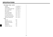
SPECIFICATIONS Bulb voltage, wattage × quantity Headlight Tail/brake light Front turn signal/position light Rear turn signal light Meter lighting Oil level warning light Neutral indicator light Turn signal indicator light Engine trouble warning light High beam indicator light Fuses Main fuse Signaling system fuse Backup fuse (odometer) Ignition fuse 30 A 10 A 5A 10 A 15 A 15 A 12 V, 60/55 W × 1 12 V, 8/27 W × 1 12 V, 27/8 W × 2 12 V, 27 W × 2 14 V, 1.4 W × 2 12 V, 1.7 W × 1 12 V, 1.7 W × 1 ...
SPECIFICATIONS Bulb voltage, wattage × quantity Headlight Tail/brake light Front turn signal/position light Rear turn signal light Meter lighting Oil level warning light Neutral indicator light Turn signal indicator light Engine trouble warning light High beam indicator light Fuses Main fuse Signaling system fuse Backup fuse (odometer) Ignition fuse 30 A 10 A 5A 10 A 15 A 15 A 12 V, 60/55 W × 1 12 V, 8/27 W × 1 12 V, 27/8 W × 2 12 V, 27 W × 2 14 V, 1.4 W × 2 12 V, 1.7 W × 1 12 V, 1.7 W × 1 ...
Owners Manual
Page 114
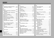
... fork, checking ...6-26 Fuel ...3-7 Fuel cock...3-9 Fuel tank cap...3-7 Fuses, replacing ...6-29 N Neutral indicator light ...3-2 Noise regulation ...9-4 B Battery ...6-28 Brake and clutch levers, checking and lubricating ...6-25 Brake and shift pedals, checking and lubricating ...6-25 Brake fluid, changing ...6-24 Brake fluid level, checking...6-23 Brake lever...3-5 Brake lever free play, adjusting ...6-19 Brake light switch (rear), adjusting ...6-21 Brake pads, checking...6-22 Brake pedal...3-6 Brake pedal position, adjusting ...6-21 O Oil level warning light ...3-2 P Panel, removing and...
... fork, checking ...6-26 Fuel ...3-7 Fuel cock...3-9 Fuel tank cap...3-7 Fuses, replacing ...6-29 N Neutral indicator light ...3-2 Noise regulation ...9-4 B Battery ...6-28 Brake and clutch levers, checking and lubricating ...6-25 Brake and shift pedals, checking and lubricating ...6-25 Brake fluid, changing ...6-24 Brake fluid level, checking...6-23 Brake lever...3-5 Brake lever free play, adjusting ...6-19 Brake light switch (rear), adjusting ...6-21 Brake pads, checking...6-22 Brake pedal...3-6 Brake pedal position, adjusting ...6-21 O Oil level warning light ...3-2 P Panel, removing and...