

Owners Manual
Page 12
... specifically designed for the proper selection, installation and use on both sides of non-Yamaha accessories. Check accessory mounts and cargo restraints frequently. 3. Since Yamaha cannot test all other accessories that would impair the performance of 203 kg (448 lb). Keep the following in any way reduce ground clearance or cornering clearance, limit suspension travel, steering travel or control operation, or obscure lights...
... specifically designed for the proper selection, installation and use on both sides of non-Yamaha accessories. Check accessory mounts and cargo restraints frequently. 3. Since Yamaha cannot test all other accessories that would impair the performance of 203 kg (448 lb). Keep the following in any way reduce ground clearance or cornering clearance, limit suspension travel, steering travel or control operation, or obscure lights...
Owners Manual
Page 13
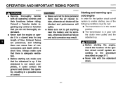
... time in cross winds. Never start the engine or let it run for any gasoline on the engine or exhaust system when refueling. The exhaust fumes are poisonous and may become unstable in a closed area. Take care not to lift the motorcycle, or the motorcycle may cause loss of lights or engine power. 1 Gasoline and exhaust gas 1. These accessories may limit control ability, therefore, such accessories...
... time in cross winds. Never start the engine or let it run for any gasoline on the engine or exhaust system when refueling. The exhaust fumes are poisonous and may become unstable in a closed area. Take care not to lift the motorcycle, or the motorcycle may cause loss of lights or engine power. 1 Gasoline and exhaust gas 1. These accessories may limit control ability, therefore, such accessories...

Owners Manual
Page 21
INSTRUMENT AND CONTROL FUNCTIONS Main switch/steering lock ...3-1 Indicator and warning lights ...3-2 Speedometer unit ...3-3 Handlebar switches ...3-3 Clutch lever ...3-4 Shift pedal ...3-5 Brake lever ...3-5 Brake pedal ...3-5 Fuel tank cap ...3-6 Fuel ...3-7 Fuel cock ...3-8 Starter (choke) lever...3-9 Seats ...3-9 Helmet holder ...3-11 Storage compartment ...3-11 Adjusting the shock absorber assembly ...3-13 Luggage strap holders ...3-15 Sidestand ...3-16 Ignition circuit cut-off system ...3-16 3
INSTRUMENT AND CONTROL FUNCTIONS Main switch/steering lock ...3-1 Indicator and warning lights ...3-2 Speedometer unit ...3-3 Handlebar switches ...3-3 Clutch lever ...3-4 Shift pedal ...3-5 Brake lever ...3-5 Brake pedal ...3-5 Fuel tank cap ...3-6 Fuel ...3-7 Fuel cock ...3-8 Starter (choke) lever...3-9 Seats ...3-9 Helmet holder ...3-11 Storage compartment ...3-11 Adjusting the shock absorber assembly ...3-13 Luggage strap holders ...3-15 Sidestand ...3-16 Ignition circuit cut-off system ...3-16 3
Owners Manual
Page 23
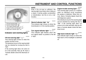
... the engine is defective. The electrical circuit of the warning light can be checked by turning the key to "ON". INSTRUMENT AND CONTROL FUNCTIONS NOTE: Even if the oil level is sufficient, the warning light may flicker when riding on when the transmission is in the neutral position. Oil level warning light " " Neutral indicator light " " Turn signal indicator light " " Engine trouble warning light " " High beam indicator light " " EAU03034 Neutral indicator light " " This indicator light comes...
... the engine is defective. The electrical circuit of the warning light can be checked by turning the key to "ON". INSTRUMENT AND CONTROL FUNCTIONS NOTE: Even if the oil level is sufficient, the warning light may flicker when riding on when the transmission is in the neutral position. Oil level warning light " " Neutral indicator light " " Turn signal indicator light " " Engine trouble warning light " " High beam indicator light " " EAU03034 Neutral indicator light " " This indicator light comes...
Owners Manual
Page 25
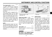
... motorcycle overturns or when the throttle cable is equipped with the starter. INSTRUMENT AND CONTROL FUNCTIONS EAU04218 Turn signal switch " / " To signal a right-hand turn, push this switch to the center position. Since this model is stuck. Start switch " " / " EAU03890 1. When released, the switch returns to " ". However, the turn , push this switch to " " to the center position. Set this switch to " " before starting the engine. To disengage the clutch, pull the lever toward...
... motorcycle overturns or when the throttle cable is equipped with the starter. INSTRUMENT AND CONTROL FUNCTIONS EAU04218 Turn signal switch " / " To signal a right-hand turn, push this switch to the center position. Since this model is stuck. Start switch " " / " EAU03890 1. When released, the switch returns to " ". However, the turn , push this switch to " " to the center position. Set this switch to " " before starting the engine. To disengage the clutch, pull the lever toward...
Owners Manual
Page 28
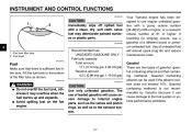
... Your Yamaha engine has been designed to the bottom of the filler tube as to the fuel system or vehicle performance problems. _ WARNING G Do not overfill the fuel tank, otherwise it can be used if the ethanol content does not exceed 10%. Gasohol containing methanol is sufficient fuel in the tank. INSTRUMENT AND CONTROL FUNCTIONS EAU00185 CAUTION: Immediately wipe off spilled fuel with a pump octane...
... Your Yamaha engine has been designed to the bottom of the filler tube as to the fuel system or vehicle performance problems. _ WARNING G Do not overfill the fuel tank, otherwise it can be used if the ethanol content does not exceed 10%. Gasohol containing methanol is sufficient fuel in the tank. INSTRUMENT AND CONTROL FUNCTIONS EAU00185 CAUTION: Immediately wipe off spilled fuel with a pump octane...
Owners Manual
Page 37
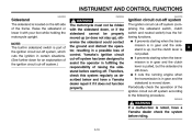
... sidestand before riding. _ _ 3-16 Yamaha's ignition circuit cut-off . INSTRUMENT AND CONTROL FUNCTIONS EAU00330 EW000044 EAU03720 Sidestand The sidestand is located on the left side of the ignition circuit cut-off system, which cuts the ignition in gear and the clutch lever is pulled, but the clutch lever is not pulled. G It prevents starting when the transmission is in certain situations...
... sidestand before riding. _ _ 3-16 Yamaha's ignition circuit cut-off . INSTRUMENT AND CONTROL FUNCTIONS EAU00330 EW000044 EAU03720 Sidestand The sidestand is located on the left side of the ignition circuit cut-off system, which cuts the ignition in gear and the clutch lever is pulled, but the clutch lever is not pulled. G It prevents starting when the transmission is in certain situations...

Owners Manual
Page 41
...Control cables 6-24 Wheels and tires 6-15-6-17 Brake and shift pedals Brake and clutch levers Sidestand Chassis fasteners Instruments, lights, signals and switches Sidestand switch...have Yamaha dealer check vehicle. 6-25 6-25 6-25 - - 3-16 4 4-2 Check air pressure. Correct if necessary. PRE-OPERATION CHECKS ITEM Throttle ...Yamaha dealer adjust cable free play and lubricate cable and grip housing. • Make sure that all nuts, bolts and screws are properly tightened. • Tighten if necessary. • Check operation. • Correct if necessary. • Check operation of ignition...
...Control cables 6-24 Wheels and tires 6-15-6-17 Brake and shift pedals Brake and clutch levers Sidestand Chassis fasteners Instruments, lights, signals and switches Sidestand switch...have Yamaha dealer check vehicle. 6-25 6-25 6-25 - - 3-16 4 4-2 Check air pressure. Correct if necessary. PRE-OPERATION CHECKS ITEM Throttle ...Yamaha dealer adjust cable free play and lubricate cable and grip housing. • Make sure that all nuts, bolts and screws are properly tightened. • Tighten if necessary. • Check operation. • Correct if necessary. • Check operation of ignition...
Owners Manual
Page 44
Consult a Yamaha dealer regarding any length of time. G Never start the engine or operate it could contact the ground and distract the operator, resulting in gear with the clutch lever pulled and the sidestand up. G Before starting out, make sure that there is in a closed area for any control or function that the sidestand is up a cold engine In order for the ignition circuit...
Consult a Yamaha dealer regarding any length of time. G Never start the engine or operate it could contact the ground and distract the operator, resulting in gear with the clutch lever pulled and the sidestand up. G Before starting out, make sure that there is in a closed area for any control or function that the sidestand is up a cold engine In order for the ignition circuit...
Owners Manual
Page 47
... almost completely stopped. Open the throttle part way and gradually release the clutch lever. 7. Follow the same procedure when shifting to slow the motorcycle. 2. Shift the transmission into first gear. If the engine is about to stall or runs very roughly, pull the clutch lever in and use the clutch while changing gears to avoid damaging the engine, transmission, and drive train, which are not designed...
... almost completely stopped. Open the throttle part way and gradually release the clutch lever. 7. Follow the same procedure when shifting to slow the motorcycle. 2. Shift the transmission into first gear. If the engine is about to stall or runs very roughly, pull the clutch lever in and use the clutch while changing gears to avoid damaging the engine, transmission, and drive train, which are not designed...
Owners Manual
Page 50
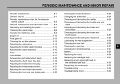
PERIODIC MAINTENANCE AND MINOR REPAIR Periodic maintenance ...6-1 Owner's tool kit ...6-1 Periodic maintenance chart for the emission control system ...6-3 General maintenance and lubrication chart ...6-4 Removing and installing the panel ...6-7 Checking the spark plugs ...6-8 Canister (for California only) ...6-9 Engine oil ...6-10 Final gear oil ...6-12 Cleaning the air filter element ...6-13 Adjusting the carburetors ...6-14 Adjusting the throttle cable free play ...6-15 Adjusting the valve clearance ...6-15 Tires ...6-15 Cast wheels ...6-17 Accessories and replacement parts...
PERIODIC MAINTENANCE AND MINOR REPAIR Periodic maintenance ...6-1 Owner's tool kit ...6-1 Periodic maintenance chart for the emission control system ...6-3 General maintenance and lubrication chart ...6-4 Removing and installing the panel ...6-7 Checking the spark plugs ...6-8 Canister (for California only) ...6-9 Engine oil ...6-10 Final gear oil ...6-12 Cleaning the air filter element ...6-13 Adjusting the carburetors ...6-14 Adjusting the throttle cable free play ...6-15 Adjusting the valve clearance ...6-15 Tires ...6-15 Cast wheels ...6-17 Accessories and replacement parts...
Owners Manual
Page 53
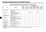
PERIODIC MAINTENANCE AND MINOR REPAIR EAU00471 Periodic maintenance chart for damage. • Replace if necessary. √ √ √ √ √ √ 2 Spark plugs √ Replace. √ Replace. √ 3 * 4 * 5 * 6 * 7 * 8 * 9 * Crankcase ventilation system Fuel line Fuel filter √ √ √ √ √ √ √ √ √ √ √ 6 Exhaust system Carburetor synchronization Idle speed Evaporative emission control system** √ √ √ √ √ √ * Since these items require...
PERIODIC MAINTENANCE AND MINOR REPAIR EAU00471 Periodic maintenance chart for damage. • Replace if necessary. √ √ √ √ √ √ 2 Spark plugs √ Replace. √ Replace. √ 3 * 4 * 5 * 6 * 7 * 8 * 9 * Crankcase ventilation system Fuel line Fuel filter √ √ √ √ √ √ √ √ √ √ √ 6 Exhaust system Carburetor synchronization Idle speed Evaporative emission control system** √ √ √ √ √ √ * Since these items require...

Owners Manual
Page 55
...; √ 12 13 * Front fork 14 * Steering bearings √ √ √ Repack. √ 6 15 16 17 18 19 * * * * * Wheel bearings Wheels Sidestand switch Tires Shock absorber assembly Chassis fasteners 20 * 21 * Throttle grip housing and cable √ √ √ √ √ √ * Since these items require special tools, data and technical skills, have a Yamaha dealer perform the service. 6-5 PERIODIC MAINTENANCE AND MINOR REPAIR INITIAL No.
...; √ 12 13 * Front fork 14 * Steering bearings √ √ √ Repack. √ 6 15 16 17 18 19 * * * * * Wheel bearings Wheels Sidestand switch Tires Shock absorber assembly Chassis fasteners 20 * 21 * Throttle grip housing and cable √ √ √ √ √ √ * Since these items require special tools, data and technical skills, have a Yamaha dealer perform the service. 6-5 PERIODIC MAINTENANCE AND MINOR REPAIR INITIAL No.

Owners Manual
Page 59
... canister for California only) This model is equipped with a canister to specification. Install the spark plug cap. 5. G Check each hose connection. Measure the spark plug gap with the spark plug wrench, and then tighten it if necessary. 4. Install the spark plug with a wire thickness gauge and, if necessary, adjust the gap to prevent the discharging of fuel vapor into the atmosphere. Replace if damaged. Clean it...
... canister for California only) This model is equipped with a canister to specification. Install the spark plug cap. 5. G Check each hose connection. Measure the spark plug gap with the spark plug wrench, and then tighten it if necessary. 4. Install the spark plug with a wire thickness gauge and, if necessary, adjust the gap to prevent the discharging of fuel vapor into the atmosphere. Replace if damaged. Clean it...

Owners Manual
Page 71
... the braking performance, which is activated by the brake pedal, is air in the hydraulic system. If necessary, adjust the brake light switch as shown. To make the brake light come on earlier, turn the adjusting nut in ) above the top of air in the hydraulic system, have a Yamaha dealer adjust it. Rear brake light switch 2. PERIODIC MAINTENANCE AND MINOR REPAIR EW000109 a. Turn the adjusting nut while holding the rear brake light switch...
... the braking performance, which is activated by the brake pedal, is air in the hydraulic system. If necessary, adjust the brake light switch as shown. To make the brake light come on earlier, turn the adjusting nut in ) above the top of air in the hydraulic system, have a Yamaha dealer adjust it. Rear brake light switch 2. PERIODIC MAINTENANCE AND MINOR REPAIR EW000109 a. Turn the adjusting nut while holding the rear brake light switch...

Owners Manual
Page 79
... 4. Fuse box Headlight fuse Signaling system fuse Ignition fuse Carburetor heater fuse Backup fuse (odometer) Spare fuse (× 3) EAU04210 Replacing the fuses The main fuse is required. G To charge a sealed-type (MF) battery, a special (constantvoltage) battery charger is located under the ignitor unit panel. Positive terminal 2. If you do not have access to the battery terminals. 6 _ CAUTION: keep the battery G Always charged. After installation, make sure that the battery leads...
... 4. Fuse box Headlight fuse Signaling system fuse Ignition fuse Carburetor heater fuse Backup fuse (odometer) Spare fuse (× 3) EAU04210 Replacing the fuses The main fuse is required. G To charge a sealed-type (MF) battery, a special (constantvoltage) battery charger is located under the ignitor unit panel. Positive terminal 2. If you do not have access to the battery terminals. 6 _ CAUTION: keep the battery G Always charged. After installation, make sure that the battery leads...

Owners Manual
Page 80
PERIODIC MAINTENANCE AND MINOR REPAIR Specified fuses: Main fuse: Backup fuse (odometer): Ignition fuse: Headlight fuse: Carburetor heater fuse: Signaling system fuse : 1. Remove the quick fasteners shown by pushing the center in question to check if the device operates. 7. Pull the ignitor unit panel outward to "OFF" and turn on the electrical circuit in with a screwdriver, then pulling the fastener out. 3. Turn the key to the electrical system and possibly a fire. _ _ 6 6. Ignitor...
PERIODIC MAINTENANCE AND MINOR REPAIR Specified fuses: Main fuse: Backup fuse (odometer): Ignition fuse: Headlight fuse: Carburetor heater fuse: Signaling system fuse : 1. Remove the quick fasteners shown by pushing the center in question to check if the device operates. 7. Pull the ignitor unit panel outward to "OFF" and turn on the electrical circuit in with a screwdriver, then pulling the fastener out. 3. Turn the key to the electrical system and possibly a fire. _ _ 6 6. Ignitor...

Owners Manual
Page 95
...) 113 mm (4.45 in) Coil spring / oil damper Coil spring / gas-oil damper Telescopic fork Swingarm (link suspension) 203 kg (448 lb) Rear Type Operation Fluid Single disc brake Right foot DOT 4 * Total weight of rider, passenger, cargo and accessories Wheels Front 8 Brakes Front 8-3 SPECIFICATIONS Maximum load* Tire air pressure (measured or cold tires) Up to 90 kg (198 lb)* Front Rear 90 kg (198 lb)-maximum* Front Rear 225 kPa (2.25 kgf/cm2...
...) 113 mm (4.45 in) Coil spring / oil damper Coil spring / gas-oil damper Telescopic fork Swingarm (link suspension) 203 kg (448 lb) Rear Type Operation Fluid Single disc brake Right foot DOT 4 * Total weight of rider, passenger, cargo and accessories Wheels Front 8 Brakes Front 8-3 SPECIFICATIONS Maximum load* Tire air pressure (measured or cold tires) Up to 90 kg (198 lb)* Front Rear 90 kg (198 lb)-maximum* Front Rear 225 kPa (2.25 kgf/cm2...

Owners Manual
Page 96
SPECIFICATIONS Bulb voltage, wattage × quantity Headlight Tail/brake light Front turn signal/position light Rear turn signal light Meter lighting Oil level warning light Neutral indicator light Turn signal indicator light Engine trouble warning light High beam indicator light Fuses Main fuse Signaling system fuse Backup fuse (odometer) Ignition fuse Headlight fuse Carburetor heater fuse 30 A 10 A 5A 10 A 15 A 15 A 12 V, 60/55 W × 1 12 V, 8/27 W × 1 12 V, 27/8 W × 2 12 V, 27 W × 2 14 V, 1.4 W × 2 12 V, 1.7 W × 1 12 V, 1.7 W × 1 ...
SPECIFICATIONS Bulb voltage, wattage × quantity Headlight Tail/brake light Front turn signal/position light Rear turn signal light Meter lighting Oil level warning light Neutral indicator light Turn signal indicator light Engine trouble warning light High beam indicator light Fuses Main fuse Signaling system fuse Backup fuse (odometer) Ignition fuse Headlight fuse Carburetor heater fuse 30 A 10 A 5A 10 A 15 A 15 A 12 V, 60/55 W × 1 12 V, 8/27 W × 1 12 V, 27/8 W × 2 12 V, 27 W × 2 14 V, 1.4 W × 2 12 V, 1.7 W × 1 12 V, 1.7 W × 1 ...

Owners Manual
Page 108
... fork, checking ...6-26 Fuel ...3-7 Fuel cock...3-8 Fuel tank cap...3-6 Fuses, replacing ...6-29 N Neutral indicator light ...3-2 Noise regulation ...9-4 B Battery ...6-28 Brake and clutch levers, checking and lubricating ...6-25 Brake and shift pedals, checking and lubricating ...6-25 Brake fluid, changing ...6-24 Brake fluid level, checking...6-23 Brake lever...3-5 Brake lever free play, adjusting ...6-19 Brake light switch (rear), adjusting ...6-21 Brake pads, checking...6-22 Brake pedal...3-5 Brake pedal position, adjusting ...6-21 O Oil level warning light ...3-2 P Panel, removing and...
... fork, checking ...6-26 Fuel ...3-7 Fuel cock...3-8 Fuel tank cap...3-6 Fuses, replacing ...6-29 N Neutral indicator light ...3-2 Noise regulation ...9-4 B Battery ...6-28 Brake and clutch levers, checking and lubricating ...6-25 Brake and shift pedals, checking and lubricating ...6-25 Brake fluid, changing ...6-24 Brake fluid level, checking...6-23 Brake lever...3-5 Brake lever free play, adjusting ...6-19 Brake light switch (rear), adjusting ...6-21 Brake pads, checking...6-22 Brake pedal...3-5 Brake pedal position, adjusting ...6-21 O Oil level warning light ...3-2 P Panel, removing and...