

Owners Manual
Page 6
... WARNING AND SPECIFICATION LABELS...1-1 SAFETY INFORMATION...2-1 DESCRIPTION AND MACHINE IDENTIFICATION ...3-1 Identification number records...3-2 Key identification number...3-2 Vehicle identification number ...3-3 Model label ...3-3 CONTROL FUNCTIONS ...4-1 Main switch...4-1 2 3 4 Indicator lights...4-2 Fuel gauge ...4-4 Speedometer unit ...4-4 Handlebar switches ...4-6 Throttle lever ...4-12 Speed limiter ...4-13 Front brake lever...4-14 Rear brake pedal and lever ...4-14 Drive select lever ...4-15 Recoil starter...4-15 Fuel tank cap ...4-16 Fuel cock...4-17 Starter (choke) ...4-18 Seat...
... WARNING AND SPECIFICATION LABELS...1-1 SAFETY INFORMATION...2-1 DESCRIPTION AND MACHINE IDENTIFICATION ...3-1 Identification number records...3-2 Key identification number...3-2 Vehicle identification number ...3-3 Model label ...3-3 CONTROL FUNCTIONS ...4-1 Main switch...4-1 2 3 4 Indicator lights...4-2 Fuel gauge ...4-4 Speedometer unit ...4-4 Handlebar switches ...4-6 Throttle lever ...4-12 Speed limiter ...4-13 Front brake lever...4-14 Rear brake pedal and lever ...4-14 Drive select lever ...4-15 Recoil starter...4-15 Fuel tank cap ...4-16 Fuel cock...4-17 Starter (choke) ...4-18 Seat...
Owners Manual
Page 7
5 PRE-OPERATION CHECKS ...5-1 Front and rear brakes ...5-2 Fuel ...5-4 Engine oil ...5-6 Final gear oil...5-7 Differential gear oil ...5-7 Throttle lever ...5-7 Fittings and Fasteners ...5-8 Lights...5-8 Switches...5-8 Tires ...5-8 How to measure tire pressure...5-10 Tire wear limit...5-11 OPERATION...6-1 Starting a cold engine ...6-1 Starting a warm engine...6-3 Warming up...6-3 Drive select lever operation and reverse driving ...6-4 Engine break-in ...6-7 Parking...6-8 Parking on a slope...6-9 Accessories and loading ...6-10 7 RIDING YOUR ATV ...7-1 Getting to know your ATV ...7-3 Ride ...
5 PRE-OPERATION CHECKS ...5-1 Front and rear brakes ...5-2 Fuel ...5-4 Engine oil ...5-6 Final gear oil...5-7 Differential gear oil ...5-7 Throttle lever ...5-7 Fittings and Fasteners ...5-8 Lights...5-8 Switches...5-8 Tires ...5-8 How to measure tire pressure...5-10 Tire wear limit...5-11 OPERATION...6-1 Starting a cold engine ...6-1 Starting a warm engine...6-3 Warming up...6-3 Drive select lever operation and reverse driving ...6-4 Engine break-in ...6-7 Parking...6-8 Parking on a slope...6-9 Accessories and loading ...6-10 7 RIDING YOUR ATV ...7-1 Getting to know your ATV ...7-3 Ride ...
Owners Manual
Page 8
......8-1 Owner's manual and tool kit...8-1 Periodic maintenance/ lubrication ...8-3 Panel removal and installation ...8-5 Engine oil...8-12 Final gear oil ...8-16 Differential gear oil...8-19 Cooling system...8-21 Changing the coolant ...8-22 Axle boots...8-26 Spark plug inspection...8-26 Air filter element cleaning...8-29 V-belt cooling duct check hose ...8-32 V-belt case drain plug...8-32 Spark arrester cleaning ...8-33 Carburetor adjustment...8-34 Idle speed adjustment ...8-35 Valve clearance adjustment ...8-36 Throttle lever adjustment...8-36 Front brake pad inspection...8-37 Rear brake pad...
......8-1 Owner's manual and tool kit...8-1 Periodic maintenance/ lubrication ...8-3 Panel removal and installation ...8-5 Engine oil...8-12 Final gear oil ...8-16 Differential gear oil...8-19 Cooling system...8-21 Changing the coolant ...8-22 Axle boots...8-26 Spark plug inspection...8-26 Air filter element cleaning...8-29 V-belt cooling duct check hose ...8-32 V-belt case drain plug...8-32 Spark arrester cleaning ...8-33 Carburetor adjustment...8-34 Idle speed adjustment ...8-35 Valve clearance adjustment ...8-36 Throttle lever adjustment...8-36 Front brake pad inspection...8-37 Rear brake pad...
Owners Manual
Page 20
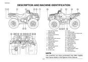
Radiator cap 7. Air filter case 13. 14. 15. 16. 17. 18. 19. 20. 21. 22. 23. 24. 25. 26. 27. 28. 29. Front spring preload adjusting ring 8. Front spring preload adjusting ring 11. Fuel cock 12. Rear brake fluid reservoir 6. Brake pedal 10. V-belt case 9. Fuses Tail/brake light V-belt cooling duct check hose Coolant reservoir Oil filter cartridge Engine oil dipstick Rear brake lever Left handlebar switches Starter (choke) Drive select lever Speedometer unit Main switch Fuel tank cap Auxiliary DC jack Right handlebar...
Radiator cap 7. Air filter case 13. 14. 15. 16. 17. 18. 19. 20. 21. 22. 23. 24. 25. 26. 27. 28. 29. Front spring preload adjusting ring 8. Front spring preload adjusting ring 11. Fuel cock 12. Rear brake fluid reservoir 6. Brake pedal 10. V-belt case 9. Fuses Tail/brake light V-belt cooling duct check hose Coolant reservoir Oil filter cartridge Engine oil dipstick Rear brake lever Left handlebar switches Starter (choke) Drive select lever Speedometer unit Main switch Fuel tank cap Auxiliary DC jack Right handlebar...

Owners Manual
Page 29
... starter motor will not start or run when the engine stop the engine, especially in the " " position. CAUTION: _ Do not use the headlights with the engine turned off for details.) 4-7 Engine stop switch is in an emergency. CAUTION: See starting the engine. (See page 6-1 for more than thirty minutes. The engine will not operate properly. The battery may discharge to stop switch is pushed. The engine stop switch controls ignition...
... starter motor will not start or run when the engine stop the engine, especially in the " " position. CAUTION: _ Do not use the headlights with the engine turned off for details.) 4-7 Engine stop switch is in an emergency. CAUTION: See starting the engine. (See page 6-1 for more than thirty minutes. The engine will not operate properly. The battery may discharge to stop switch is pushed. The engine stop switch controls ignition...
Owners Manual
Page 34
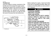
... Once the engine is released. Because the throttle is spring-loaded, the machine will decelerate, and the engine will increase the engine speed. WARNING POTENTIAL HAZARD Malfunction of the machine by varying the throttle position. Regulate the speed of throttle. Consult a Yamaha dealer if you can't find or solve the problem yourself. 1. Before starting the engine, check the throttle to be hard to an idle any time the hand...
... Once the engine is released. Because the throttle is spring-loaded, the machine will decelerate, and the engine will increase the engine speed. WARNING POTENTIAL HAZARD Malfunction of the machine by varying the throttle position. Regulate the speed of throttle. Consult a Yamaha dealer if you can't find or solve the problem yourself. 1. Before starting the engine, check the throttle to be hard to an idle any time the hand...
Owners Manual
Page 46
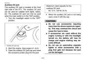
... rated capacity for suitable work lights, radios, etc. Auxiliary DC jack cap G 2. Open the auxiliary DC jack cap and insert the accessory power plug into the jack. 4-24 Do not use an automotive cigarette lighter or other accessories with a plug that gets hot because the jack can only be used without the engine running or with the cap. The auxiliary DC jack can be used , cover it with the headlight turned on, the battery...
... rated capacity for suitable work lights, radios, etc. Auxiliary DC jack cap G 2. Open the auxiliary DC jack cap and insert the accessory power plug into the jack. 4-24 Do not use an automotive cigarette lighter or other accessories with a plug that gets hot because the jack can only be used without the engine running or with the cap. The auxiliary DC jack can be used , cover it with the headlight turned on, the battery...
Owners Manual
Page 51
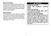
If there is leaking out of every ride. Brake operation Test the brakes at the start of the pipe joints or brake fluid reservoirs. If the brakes do not provide proper braking performance, inspect the brake pads for one minute. Brake fluid leakage Check to see if any brake fluid is any problem with improperly operating brakes. Apply the brakes firmly for wear. (See pages 8-37-8-38.) WARNING POTENTIAL HAZARD Riding...
If there is leaking out of every ride. Brake operation Test the brakes at the start of the pipe joints or brake fluid reservoirs. If the brakes do not provide proper braking performance, inspect the brake pads for one minute. Brake fluid leakage Check to see if any brake fluid is any problem with improperly operating brakes. Apply the brakes firmly for wear. (See pages 8-37-8-38.) WARNING POTENTIAL HAZARD Riding...

Owners Manual
Page 56
... this ATV with improper or uneven tire pressure. Repair as necessary for correct tightening torque. Other tire combinations are in working condition. ACE-01E Lights Check the headlights and tail/brake light to the Service Manual for proper operation. WHAT CAN HAPPEN Use of improper tires on this ATV, or operation of accident. Manufacturer Front Rear CHENG SHIN CHENG SHIN Size AT25 × 8-12 AT25 ×...
... this ATV with improper or uneven tire pressure. Repair as necessary for correct tightening torque. Other tire combinations are in working condition. ACE-01E Lights Check the headlights and tail/brake light to the Service Manual for proper operation. WHAT CAN HAPPEN Use of improper tires on this ATV, or operation of accident. Manufacturer Front Rear CHENG SHIN CHENG SHIN Size AT25 × 8-12 AT25 ×...
Owners Manual
Page 60
Shift the drive select lever into the neutral or park position. HOW TO AVOID THE HAZARD Read the Owner's Manual carefully. Apply the rear brake lever. 2. EBU00161 EBU00672 OPERATION WARNING Indicates a potential hazard that could cause an accident or injury. Turn the fuel cock to " ". 4. WHAT CAN HAPPEN Loss of control, which could lead to an accident or collision. WARNING POTENTIAL HAZARD Operating...
Shift the drive select lever into the neutral or park position. HOW TO AVOID THE HAZARD Read the Owner's Manual carefully. Apply the rear brake lever. 2. EBU00161 EBU00672 OPERATION WARNING Indicates a potential hazard that could cause an accident or injury. Turn the fuel cock to " ". 4. WHAT CAN HAPPEN Loss of control, which could lead to an accident or collision. WARNING POTENTIAL HAZARD Operating...

Owners Manual
Page 61
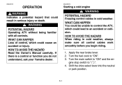
... inspect its electric circuit. Position 3 : Cold engine startambient temperature above 25 °C (80 °F) and warm engine start switch. 6-2 G The engine can be started in any gear if the rear brake lever is recommended to shift into neutral or park before starting the engine. 5. Position 2 : Cold engine startambient temperature at 0 °C (30 °F)-30 °C (90 °F) and warming up position. Starter (choke) lever 2. NOTE: G When the drive select...
... inspect its electric circuit. Position 3 : Cold engine startambient temperature above 25 °C (80 °F) and warm engine start switch. 6-2 G The engine can be started in any gear if the rear brake lever is recommended to shift into neutral or park before starting the engine. 5. Position 2 : Cold engine startambient temperature at 0 °C (30 °F)-30 °C (90 °F) and warming up position. Starter (choke) lever 2. NOTE: G When the drive select...

Owners Manual
Page 64
... obstacles, then release the rear brake pedal. 6-5 Bring the machine to a complete stop and return the throttle lever to the synchronizing mechanism in reverse, the reverse indicator light should be shifted into or from reverse to Park NOTE: The drive select lever cannot be on until the ATV starts moving the drive select lever along the shift guide. 1. Apply the rear brake pedal. 3. G Due...
... obstacles, then release the rear brake pedal. 6-5 Bring the machine to a complete stop and return the throttle lever to the synchronizing mechanism in reverse, the reverse indicator light should be shifted into or from reverse to Park NOTE: The drive select lever cannot be on until the ATV starts moving the drive select lever along the shift guide. 1. Apply the rear brake pedal. 3. G Due...

Owners Manual
Page 93
... area before trying more difficult to lose traction, reducing control and increasing the possibility of directional control. Make sure that the engine and exhaust pipe will start the engine. do not allow skin or clothing to the engine or drive train may lift off -road use of the brakes can cause the tires to perform on paved surfaces: the ATV is designed for...
... area before trying more difficult to lose traction, reducing control and increasing the possibility of directional control. Make sure that the engine and exhaust pipe will start the engine. do not allow skin or clothing to the engine or drive train may lift off -road use of the brakes can cause the tires to perform on paved surfaces: the ATV is designed for...

Owners Manual
Page 116
... fuel hose for leakage. Check and adjust idle speed/starter operation. Check for cracks or damage. Replace gasket(s) if necessary. Check operation/fluid leakage. (See NOTE page 8-4.) Correct if necessary. EBU00261 PERIODIC MAINTENANCE/LUBRICATION ITEM ROUTINE Whichever comes first mile (km) hours 200 (320) 20 INITIAL 750 (1,200) 75 1,500 (2,400) 150 EVERY 1,500 3,000 (2,400) (4,800) 150 300 Valves* Cooling system Spark plug Air filter...
... fuel hose for leakage. Check and adjust idle speed/starter operation. Check for cracks or damage. Replace gasket(s) if necessary. Check operation/fluid leakage. (See NOTE page 8-4.) Correct if necessary. EBU00261 PERIODIC MAINTENANCE/LUBRICATION ITEM ROUTINE Whichever comes first mile (km) hours 200 (320) 20 INITIAL 750 (1,200) 75 1,500 (2,400) 150 EVERY 1,500 3,000 (2,400) (4,800) 150 300 Valves* Cooling system Spark plug Air filter...

Owners Manual
Page 117
Drive shaft universal joint* • Lubricate.** Engine mount* • Check for looseness/damage. Front axle boots* • Replace if damaged. • Check all chassis fittings and fasteners. WARNING 8-4 Indicates a potential hazard that these items be serviced by a Yamaha dealer. ** Lithium-soap-based grease Rear brake* NOTE: G Recommended brake fluid: DOT 4 G Brake fluid replacement: • When disassembling the master cylinder or caliper, replace the brake fluid. Front and rear • Check operation. suspension* •...
Drive shaft universal joint* • Lubricate.** Engine mount* • Check for looseness/damage. Front axle boots* • Replace if damaged. • Check all chassis fittings and fasteners. WARNING 8-4 Indicates a potential hazard that these items be serviced by a Yamaha dealer. ** Lithium-soap-based grease Rear brake* NOTE: G Recommended brake fluid: DOT 4 G Brake fluid replacement: • When disassembling the master cylinder or caliper, replace the brake fluid. Front and rear • Check operation. suspension* •...

Owners Manual
Page 156
... air must be performed by the brake pedal and rear brake lever, is properly adjusted when the brake light comes on later, turn the adjusting nut in place. Remove panel B. (See page 8-8 for panel removal and installation procedures.) 2. Rear brake light switch 2. Adjusting nut Replacement of brake components requires professional knowledge. Turn the adjusting nut while holding the rear brake light switch in direction a. EBU01120 l WARNING POTENTIAL HAZARD Operating with improperly serviced or...
... air must be performed by the brake pedal and rear brake lever, is properly adjusted when the brake light comes on later, turn the adjusting nut in place. Remove panel B. (See page 8-8 for panel removal and installation procedures.) 2. Rear brake light switch 2. Adjusting nut Replacement of brake components requires professional knowledge. Turn the adjusting nut while holding the rear brake light switch in direction a. EBU01120 l WARNING POTENTIAL HAZARD Operating with improperly serviced or...

Owners Manual
Page 157
... kinked. Recommended lubricant: Yamaha chain and cable lube or SAE 10W30 motor oil 8-44 Brake lever and brake pedal lubrication Lubricate the pivoting parts. Replace damaged cables. Lubricate the inner cables and the cable ends. HOW TO AVOID THE HAZARD Inspect cables frequently. Operation of control cables becomes damaged. EBU00356 EBU00717 Cable inspection and lubrication WARNING POTENTIAL HAZARD Damaged...
... kinked. Recommended lubricant: Yamaha chain and cable lube or SAE 10W30 motor oil 8-44 Brake lever and brake pedal lubrication Lubricate the pivoting parts. Replace damaged cables. Lubricate the inner cables and the cable ends. HOW TO AVOID THE HAZARD Inspect cables frequently. Operation of control cables becomes damaged. EBU00356 EBU00717 Cable inspection and lubrication WARNING POTENTIAL HAZARD Damaged...

Owners Manual
Page 162
Fuse box 1. 3. 5. 7. Headlight fuse Auxiliary DC jack fuse Signaling system fuse Spare fuse (× 3) 2. Four-wheel drive fuse 6. Odometer fuse (backup) 1. Main fuse 2. Main fuse 2. 1. Spare main fuse Specified fuses: Main fuse: Headlight fuse: Ignition fuse: Auxiliary DC jack fuse: Four-wheel drive fuse: Signaling system fuse: Odometer fuse (backup): 8-49 30 A 15 A 10 A 10 A 3A 10 A 10 A Ignition fuse 4.
Fuse box 1. 3. 5. 7. Headlight fuse Auxiliary DC jack fuse Signaling system fuse Spare fuse (× 3) 2. Four-wheel drive fuse 6. Odometer fuse (backup) 1. Main fuse 2. Main fuse 2. 1. Spare main fuse Specified fuses: Main fuse: Headlight fuse: Ignition fuse: Auxiliary DC jack fuse: Four-wheel drive fuse: Signaling system fuse: Odometer fuse (backup): 8-49 30 A 15 A 10 A 10 A 3A 10 A 10 A Ignition fuse 4.

Owners Manual
Page 169
... water and dry all filler caps are properly installed. 2. Use only enough pressure to prevent water entry. CLEANING Frequent, thorough cleaning of your machine will not only enhance its appearance but will improve its general performance and extend the useful life of the exhaust pipe to do the job. If the engine case is handy for hard-to the wheel axles...
... water and dry all filler caps are properly installed. 2. Use only enough pressure to prevent water entry. CLEANING Frequent, thorough cleaning of your machine will not only enhance its appearance but will improve its general performance and extend the useful life of the exhaust pipe to do the job. If the engine case is handy for hard-to the wheel axles...

Owners Manual
Page 178
L.E.D. L.E.D. 30 A 15 A 10 A 10 A 3A 10 A 10 A YFM450FA 10-6 L.E.D. Model Bulb voltage, wattage × quantity: Headlight Tail/brake light Indicator light: Neutral indicator light Reverse indicator light Coolant temperature warning light Park indicator light High-range indicator light Low-range indicator light Differential gear lock indicator light Fuses: Main fuse Headlight fuse Ignition fuse Auxiliary DC jack fuse Four-wheel drive fuse Signaling system fuse Odometer fuse (backup) 12 V, 30/30 W × 2 12 V, 5/21 W × 1 L.E.D. L.E.D. L.E.D. L.E.D.
L.E.D. L.E.D. 30 A 15 A 10 A 10 A 3A 10 A 10 A YFM450FA 10-6 L.E.D. Model Bulb voltage, wattage × quantity: Headlight Tail/brake light Indicator light: Neutral indicator light Reverse indicator light Coolant temperature warning light Park indicator light High-range indicator light Low-range indicator light Differential gear lock indicator light Fuses: Main fuse Headlight fuse Ignition fuse Auxiliary DC jack fuse Four-wheel drive fuse Signaling system fuse Odometer fuse (backup) 12 V, 30/30 W × 2 12 V, 5/21 W × 1 L.E.D. L.E.D. L.E.D. L.E.D.
