

Owners Manual
Page 12
... and installing any way reduce ground clearance or cornering clearance, limit suspension travel, steering travel or control operation, or obscure lights or reflectors. 1 1-4 SAFETY INFORMATION Loading The total weight of the operator, passenger, accessories and cargo must personally be kept as low and close to the motorcycle as possible. Shifting weights can create unstable handling or a slow steering response. Never attach any large...
... and installing any way reduce ground clearance or cornering clearance, limit suspension travel, steering travel or control operation, or obscure lights or reflectors. 1 1-4 SAFETY INFORMATION Loading The total weight of the operator, passenger, accessories and cargo must personally be kept as low and close to the motorcycle as possible. Shifting weights can create unstable handling or a slow steering response. Never attach any large...
Owners Manual
Page 13
... due to a minimum. Always turn the engine off when refueling. Never start the engine or let it run for any gasoline on the engine or exhaust system when refueling. These accessories may limit control ability, therefore, such accessories are poisonous and may cause loss of lights or engine power. 1 Gasoline and exhaust gas 1. If electrical accessories exceed the capacity of the motorcycle's electrical system, an electric failure could result, which...
... due to a minimum. Always turn the engine off when refueling. Never start the engine or let it run for any gasoline on the engine or exhaust system when refueling. These accessories may limit control ability, therefore, such accessories are poisonous and may cause loss of lights or engine power. 1 Gasoline and exhaust gas 1. If electrical accessories exceed the capacity of the motorcycle's electrical system, an electric failure could result, which...
Owners Manual
Page 16
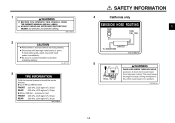
... owner's manual before servicing battery. ALWAYS WEAR AN APPROVED MOTORCYCLE HELMET, eye protection, and protective clothing. 3MX-2118K-A0 4 California only EMISSION HOSE ROUTING CARB. If electrolyte spills, wash area with fresh water immediately. This could cause the engine to stop running and lights to fail, which could result from improper routing. Electrolyte will damage metal parts or paint. SAFETY INFORMATION 1 WARNING...
... owner's manual before servicing battery. ALWAYS WEAR AN APPROVED MOTORCYCLE HELMET, eye protection, and protective clothing. 3MX-2118K-A0 4 California only EMISSION HOSE ROUTING CARB. If electrolyte spills, wash area with fresh water immediately. This could cause the engine to stop running and lights to fail, which could result from improper routing. Electrolyte will damage metal parts or paint. SAFETY INFORMATION 1 WARNING...

Owners Manual
Page 21
INSTRUMENT AND CONTROL FUNCTIONS Main switch ...3-1 Indicator and warning lights ...3-1 Speedometer unit ...3-2 Tachometer ...3-3 Coolant temperature gauge ...3-3 Handlebar switches ...3-3 Clutch lever ...3-5 Shift pedal ...3-5 Brake lever ...3-5 Brake pedal ...3-6 Fuel tank cap ...3-6 Fuel ...3-7 Starter (choke) lever ...3-8 Steering lock ...3-9 Rider seat ...3-9 Helmet holder ...3-10 Adjusting the front fork ...3-11 Adjusting the shock absorber assemblies ...3-12 Matching the front and rear suspension settings ...3-15 V-Boost ...3-16 Sidestand ...3-17 Ignition circuit cut-off system ...3-17...
INSTRUMENT AND CONTROL FUNCTIONS Main switch ...3-1 Indicator and warning lights ...3-1 Speedometer unit ...3-2 Tachometer ...3-3 Coolant temperature gauge ...3-3 Handlebar switches ...3-3 Clutch lever ...3-5 Shift pedal ...3-5 Brake lever ...3-5 Brake pedal ...3-6 Fuel tank cap ...3-6 Fuel ...3-7 Starter (choke) lever ...3-8 Steering lock ...3-9 Rider seat ...3-9 Helmet holder ...3-10 Adjusting the front fork ...3-11 Adjusting the shock absorber assemblies ...3-12 Matching the front and rear suspension settings ...3-15 V-Boost ...3-16 Sidestand ...3-17 Ignition circuit cut-off system ...3-17...
Owners Manual
Page 22
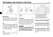
... All electrical systems are described below. Neutral indicator light "NEUTRAL" Turn signal indicator light "TURN" Fuel level warning light "FUEL" High beam indicator light "HIGH BEAM" Oil level warning light "OIL LEVEL" EAU03034 Indicator and warning lights EAU00062 CAUTION: Do not use the parking position for an extended length of time, otherwise the battery may discharge. _ _ Neutral indicator light "NEUTRAL" This indicator light comes on when the transmission is pushed to "P". The key cannot be pushed in the neutral position. INSTRUMENT AND CONTROL...
... All electrical systems are described below. Neutral indicator light "NEUTRAL" Turn signal indicator light "TURN" Fuel level warning light "FUEL" High beam indicator light "HIGH BEAM" Oil level warning light "OIL LEVEL" EAU03034 Indicator and warning lights EAU00062 CAUTION: Do not use the parking position for an extended length of time, otherwise the battery may discharge. _ _ Neutral indicator light "NEUTRAL" This indicator light comes on when the transmission is pushed to "P". The key cannot be pushed in the neutral position. INSTRUMENT AND CONTROL...
Owners Manual
Page 23
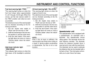
... last set the fuel reserve switch to the following procedure. 1. Shift the transmission into the neutral position or pull the clutch lever. 3. The electrical circuit of the headlight is switched on when the engine oil level is not a malfunction. _ 3 1. This information will enable you to the following procedure. 1. The speedometer shows riding speed. INSTRUMENT AND CONTROL FUNCTIONS EAU04166 EAU04167 Fuel level warning light "FUEL" This warning light comes on a slope...
... last set the fuel reserve switch to the following procedure. 1. Shift the transmission into the neutral position or pull the clutch lever. 3. The electrical circuit of the headlight is switched on when the engine oil level is not a malfunction. _ 3 1. This information will enable you to the following procedure. 1. The speedometer shows riding speed. INSTRUMENT AND CONTROL FUNCTIONS EAU04166 EAU04167 Fuel level warning light "FUEL" This warning light comes on a slope...

Owners Manual
Page 24
... 1. EC000003 Coolant temperature gauge With the key in the weather and engine load. To signal a left . Tachometer red zone EAU00101 1. Dimmer switch "LIGHTS" 2. When released, the switch returns to the left -hand turn , push this switch to monitor the engine speed and keep it within the ideal power range. Turn signal switch "TURN" 3. If the needle reaches or enters the red zone, stop the motorcycle and let the engine cool...
... 1. EC000003 Coolant temperature gauge With the key in the weather and engine load. To signal a left . Tachometer red zone EAU00101 1. Dimmer switch "LIGHTS" 2. When released, the switch returns to the left -hand turn , push this switch to monitor the engine speed and keep it within the ideal power range. Turn signal switch "TURN" 3. If the needle reaches or enters the red zone, stop the motorcycle and let the engine cool...

Owners Manual
Page 25
... turn signal lights will not selfcancel while you are stopped at an intersection. @ @ EAU01653 Fuel reserve switch "FUEL" During normal operation, this switch to "ON" before starting the engine. INSTRUMENT AND CONTROL FUNCTIONS Since this model is equipped with the starter. Start switch "START" EAU04184 3 NOTE: After switching to "RES", approximately 3 L (0.7 Imp gal, 0.8 US gal) of an emergency, such as when the motorcycle overturns or when the throttle...
... turn signal lights will not selfcancel while you are stopped at an intersection. @ @ EAU01653 Fuel reserve switch "FUEL" During normal operation, this switch to "ON" before starting the engine. INSTRUMENT AND CONTROL FUNCTIONS Since this model is equipped with the starter. Start switch "START" EAU04184 3 NOTE: After switching to "RES", approximately 3 L (0.7 Imp gal, 0.8 US gal) of an emergency, such as when the motorcycle overturns or when the throttle...
Owners Manual
Page 38
... system according to assist the operator in sidestand switch is not pulled. Periodically check the operation of the ignition circuit cut -off system (comprising the sidestand switch, clutch switch and neutral switch) has the following procedure. G It cuts the running engine when the transmission is in gear and the sidestand is noted, have a Yamaha dealer repair it if it with the sidestand down...
... system according to assist the operator in sidestand switch is not pulled. Periodically check the operation of the ignition circuit cut -off system (comprising the sidestand switch, clutch switch and neutral switch) has the following procedure. G It cuts the running engine when the transmission is in gear and the sidestand is noted, have a Yamaha dealer repair it if it with the sidestand down...

Owners Manual
Page 42
...Correct if necessary. 6-30 4 6-23-6-25 Wheels and tires Brake and shift pedals Brake and clutch levers Centerstand, sidestand Chassis fasteners Instruments, lights, signals and switches Sidestand switch Battery • Make sure that operation is smooth....fluid to specified level. PAGE Clutch 6-26, 6-29-6-30 Throttle grip 6-22, 6-31 Control cables • Make sure that operation is smooth. Check air pressure. Check hydraulic system for damage. Make sure that operation is defective, have Yamaha dealer check vehicle. • Check fluid level. • Fill with distilled water...
...Correct if necessary. 6-30 4 6-23-6-25 Wheels and tires Brake and shift pedals Brake and clutch levers Centerstand, sidestand Chassis fasteners Instruments, lights, signals and switches Sidestand switch Battery • Make sure that operation is smooth....fluid to specified level. PAGE Clutch 6-26, 6-29-6-30 Throttle grip 6-22, 6-31 Control cables • Make sure that operation is smooth. Check air pressure. Check hydraulic system for damage. Make sure that operation is defective, have Yamaha dealer check vehicle. • Check fluid level. • Fill with distilled water...
Owners Manual
Page 45
... start the engine or operate it could contact the ground and distract the operator, resulting in gear with the clutch lever pulled and the sidestand up . 5- Consult a Yamaha dealer regarding any length of the following conditions must be blocked and performance will be met: G The transmission is in a possible loss of consciousness and death within a short time. G Before starting , one of time. G The transmission...
... start the engine or operate it could contact the ground and distract the operator, resulting in gear with the clutch lever pulled and the sidestand up . 5- Consult a Yamaha dealer regarding any length of the following conditions must be blocked and performance will be met: G The transmission is in a possible loss of consciousness and death within a short time. G Before starting , one of time. G The transmission...
Owners Manual
Page 46
... the transmission is in the neutral position, the neutral indicator light should be on and completely close the throttle. (See page 3-8 for oil leakage. Turn the starter (choke) on , otherwise have a Yamaha dealer check the electrical circuit. @ @ NOTE: If the engine fails to preserve the battery. G If the oil level warning light flickers or remains on any one attempt. @ @ EC000038 @ 3. Do not crank the engine more...
... the transmission is in the neutral position, the neutral indicator light should be on and completely close the throttle. (See page 3-8 for oil leakage. Turn the starter (choke) on , otherwise have a Yamaha dealer check the electrical circuit. @ @ NOTE: If the engine fails to preserve the battery. G If the oil level warning light flickers or remains on any one attempt. @ @ EC000038 @ 3. Do not crank the engine more...
Owners Manual
Page 48
... shift points shown in the table on . 5 5-4 G Always use the brakes to withstand the shock of time with the engine off, and do not tow the motorcycle for long distances. The neutral indicator light should come on page 5-5, close the throttle, and at the same time, quickly pull the clutch lever in and use the clutch while changing gears to avoid damaging the engine, transmission, and drive...
... shift points shown in the table on . 5 5-4 G Always use the brakes to withstand the shock of time with the engine off, and do not tow the motorcycle for long distances. The neutral indicator light should come on page 5-5, close the throttle, and at the same time, quickly pull the clutch lever in and use the clutch while changing gears to avoid damaging the engine, transmission, and drive...
Owners Manual
Page 51
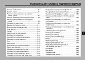
... maintenance ...6-1 Owner's tool kit ...6-1 Periodic maintenance chart for emission control system ...6-3 General maintenance and lubrication chart ...6-5 Removing and installing the cowling and panels ...6-8 Checking the spark plugs ...6-9 Canister (for California only) ...6-11 Engine oil and oil filter cartridge ...6-11 Final gear oil ...6-15 Coolant ...6-16 Cleaning the air filter element ...6-21 Adjusting the carburetors ...6-22 Adjusting the throttle cable free play ...6-22 Adjusting the valve clearance ...6-22 Tires ...6-23 Cast wheels ...6-25 Accessories...
... maintenance ...6-1 Owner's tool kit ...6-1 Periodic maintenance chart for emission control system ...6-3 General maintenance and lubrication chart ...6-5 Removing and installing the cowling and panels ...6-8 Checking the spark plugs ...6-9 Canister (for California only) ...6-11 Engine oil and oil filter cartridge ...6-11 Final gear oil ...6-15 Coolant ...6-16 Cleaning the air filter element ...6-21 Adjusting the carburetors ...6-22 Adjusting the throttle cable free play ...6-22 Adjusting the valve clearance ...6-22 Tires ...6-23 Cast wheels ...6-25 Accessories...

Owners Manual
Page 58
... skills, have a Yamaha dealer perform the service. G Hydraulic brake and clutch systems • After disassembling the brake or clutch master cylinders, caliper cylinders or clutch release cylinder, always change the fluid. Regularly check the brake and clutch fluid levels and fill the reservoirs as required. • Replace the oil seals on the inner parts of the brake or clutch master cylinders, caliper cylinders and clutch release cylinder every two years. • Replace the brake and clutch hoses every four years...
... skills, have a Yamaha dealer perform the service. G Hydraulic brake and clutch systems • After disassembling the brake or clutch master cylinders, caliper cylinders or clutch release cylinder, always change the fluid. Regularly check the brake and clutch fluid levels and fill the reservoirs as required. • Replace the oil seals on the inner parts of the brake or clutch master cylinders, caliper cylinders and clutch release cylinder every two years. • Replace the brake and clutch hoses every four years...

Owners Manual
Page 79
... the rear brake light switch The rear brake light switch, which allows you to check the brake pad wear without having to the point that the wear indicator almost touches the brake disc, have a Yamaha dealer bleed the system before braking takes effect. Turn the adjusting nut while holding the rear brake light switch in the hydraulic system. If necessary, adjust the brake light switch as a set. 6 PERIODIC MAINTENANCE AND MINOR REPAIR EW000109 WARNING...
... the rear brake light switch The rear brake light switch, which allows you to check the brake pad wear without having to the point that the wear indicator almost touches the brake disc, have a Yamaha dealer bleed the system before braking takes effect. Turn the adjusting nut while holding the rear brake light switch in the hydraulic system. If necessary, adjust the brake light switch as a set. 6 PERIODIC MAINTENANCE AND MINOR REPAIR EW000109 WARNING...

Owners Manual
Page 91
If the fuse immediately blows again, have a Yamaha dealer check the electrical system. 6 30 A 15 A 10 A 10 A 10 A Specified fuses: Main fuse: Headlight fuse: Signaling system fuse: Radiator fan fuse: Ignition fuse: 6-40 Turn the key to "ON" and turn on the electrical circuit in question to the electrical system and possibly a fire. @ @ 1. 2. 3. 4. 5. Headlight fuse Signaling system fuse Ignition fuse Radiator fan fuse Spare fuse (× 2) 3. PERIODIC MAINTENANCE AND MINOR REPAIR EC000103 CAUTION: Do not use a fuse of a higher amperage rating than recommended to avoid...
If the fuse immediately blows again, have a Yamaha dealer check the electrical system. 6 30 A 15 A 10 A 10 A 10 A Specified fuses: Main fuse: Headlight fuse: Signaling system fuse: Radiator fan fuse: Ignition fuse: 6-40 Turn the key to "ON" and turn on the electrical circuit in question to the electrical system and possibly a fire. @ @ 1. 2. 3. 4. 5. Headlight fuse Signaling system fuse Ignition fuse Radiator fan fuse Spare fuse (× 2) 3. PERIODIC MAINTENANCE AND MINOR REPAIR EC000103 CAUTION: Do not use a fuse of a higher amperage rating than recommended to avoid...

Owners Manual
Page 108
... sure to use motor oils that do not contain anti-friction modifiers. SPECIFICATIONS Model Dimensions Overall length Overall width Overall height Seat height Wheelbase Ground clearance Minimum turning radius Basic weight (with oil and full fuel tank) VMX12 VMX12C Engine Engine type Cylinder arrangement Liquid-cooled 4-stroke, DOHC V type, 4-cylinder 1,198 cm3 76 × 66 mm (3.0 × 2.6 in) 10.5:1 Electric starter Wet sump Quantity Without oil filter cartridge replacement With oil filter cartridge replacement Total amount (dry...
... sure to use motor oils that do not contain anti-friction modifiers. SPECIFICATIONS Model Dimensions Overall length Overall width Overall height Seat height Wheelbase Ground clearance Minimum turning radius Basic weight (with oil and full fuel tank) VMX12 VMX12C Engine Engine type Cylinder arrangement Liquid-cooled 4-stroke, DOHC V type, 4-cylinder 1,198 cm3 76 × 66 mm (3.0 × 2.6 in) 10.5:1 Electric starter Wet sump Quantity Without oil filter cartridge replacement With oil filter cartridge replacement Total amount (dry...

Owners Manual
Page 111
SPECIFICATIONS Bulb voltage, wattage × quantity Headlight Tail/brake light Front turn signal/position light Rear turn signal light Meter lighting Neutral indicator light High beam indicator light Turn signal indicator light Fuel level warning light Oil level warning light Fuses Main fuse Headlight fuse Signaling system fuse Radiator fan fuse Ignition fuse 30 A 15 A 10 A 10 A 10 A 12 V, 60/55 W × 1 12 V, 8/27 W × 2 12 V, 27/8 W × 2 12 V, 27 W × 2 14 V, 3 W × 2 14 V, 3 W × 1 14 V, 3 W × 1 14 V, 3 W × 1 14 V, 3 W × 1 14 V, 3 W × 1 8 8-4
SPECIFICATIONS Bulb voltage, wattage × quantity Headlight Tail/brake light Front turn signal/position light Rear turn signal light Meter lighting Neutral indicator light High beam indicator light Turn signal indicator light Fuel level warning light Oil level warning light Fuses Main fuse Headlight fuse Signaling system fuse Radiator fan fuse Ignition fuse 30 A 15 A 10 A 10 A 10 A 12 V, 60/55 W × 1 12 V, 8/27 W × 2 12 V, 27/8 W × 2 12 V, 27 W × 2 14 V, 3 W × 2 14 V, 3 W × 1 14 V, 3 W × 1 14 V, 3 W × 1 14 V, 3 W × 1 14 V, 3 W × 1 8 8-4

Owners Manual
Page 123
... clutch fluids, changing...6-30 Brake and clutch levers, checking and lubricating ...6-32 Brake and shift pedals, checking and lubricating ...6-31 Brake lever...3-5 Brake lever free play, adjusting ...6-27 Brake light switch (rear), adjusting ...6-28 Brake pads, checking...6-28 Brake pedal...3-6 Brake pedal position, adjusting ...6-27 F Final gear oil...6-15 Front fork, adjusting...3-11 Front fork, checking ...6-34 Fuel ...3-7 Fuel level warning light ...3-2 Fuel reserve switch...3-4 Fuel tank cap...3-6 Fuses, replacing ...6-39 N Neutral indicator light ...3-1 Noise regulation ...9-4 O Oil...
... clutch fluids, changing...6-30 Brake and clutch levers, checking and lubricating ...6-32 Brake and shift pedals, checking and lubricating ...6-31 Brake lever...3-5 Brake lever free play, adjusting ...6-27 Brake light switch (rear), adjusting ...6-28 Brake pads, checking...6-28 Brake pedal...3-6 Brake pedal position, adjusting ...6-27 F Final gear oil...6-15 Front fork, adjusting...3-11 Front fork, checking ...6-34 Fuel ...3-7 Fuel level warning light ...3-2 Fuel reserve switch...3-4 Fuel tank cap...3-6 Fuses, replacing ...6-39 N Neutral indicator light ...3-1 Noise regulation ...9-4 O Oil...