

Owners Manual
Page 12
... clearance, limit suspension travel, steering travel or control operation, or obscure lights or reflectors. 1 1-4 Make sure that accessories and cargo are securely attached to make sure that it to the motorcycle before using it does not in any accessories. Shifting weights can create unstable handling or slow steering response. Since Yamaha cannot test all other accessories that would impair the performance of your...
... clearance, limit suspension travel, steering travel or control operation, or obscure lights or reflectors. 1 1-4 Make sure that accessories and cargo are securely attached to make sure that it to the motorcycle before using it does not in any accessories. Shifting weights can create unstable handling or slow steering response. Since Yamaha cannot test all other accessories that would impair the performance of your...
Owners Manual
Page 13
... turn the engine off before leaving the motorcycle unattended and remove the key from his or her normal riding position. Bulky or large accessories may seriously affect the stability of lights or engine power. 1 Gasoline and exhaust gas 1. Certain accessories can create instability due to aerodynamic effects. SAFETY INFORMATION a. Never start the engine or let it run for any gasoline on the engine or exhaust system...
... turn the engine off before leaving the motorcycle unattended and remove the key from his or her normal riding position. Bulky or large accessories may seriously affect the stability of lights or engine power. 1 Gasoline and exhaust gas 1. Certain accessories can create instability due to aerodynamic effects. SAFETY INFORMATION a. Never start the engine or let it run for any gasoline on the engine or exhaust system...

Owners Manual
Page 23
INSTRUMENT AND CONTROL FUNCTIONS Main switch/steering lock ...3-1 Indicator and warning lights ...3-2 Speedometer unit ...3-3 Handlebar switches ...3-3 Clutch lever ...3-4 Shift pedal (XVS1100)...3-5 Shift pedal (XVS1100A) ...3-5 Brake lever ...3-5 Brake pedal ...3-6 Fuel tank cap ...3-7 Fuel ...3-7 Fuel cock ...3-9 Starter (choke) lever ...3-10 Seats (XVS1100) ...3-11 Seats (XVS1100A) ...3-12 Helmet holder ...3-13 Storage compartment ...3-14 Adjusting the shock absorber assembly ...3-15 Luggage strap holders ...3-18 Sidestand ...3-19 Ignition circuit cut-off system ...3-19 3
INSTRUMENT AND CONTROL FUNCTIONS Main switch/steering lock ...3-1 Indicator and warning lights ...3-2 Speedometer unit ...3-3 Handlebar switches ...3-3 Clutch lever ...3-4 Shift pedal (XVS1100)...3-5 Shift pedal (XVS1100A) ...3-5 Brake lever ...3-5 Brake pedal ...3-6 Fuel tank cap ...3-7 Fuel ...3-7 Fuel cock ...3-9 Starter (choke) lever ...3-10 Seats (XVS1100) ...3-11 Seats (XVS1100A) ...3-12 Helmet holder ...3-13 Storage compartment ...3-14 Adjusting the shock absorber assembly ...3-15 Luggage strap holders ...3-18 Sidestand ...3-19 Ignition circuit cut-off system ...3-19 3

Owners Manual
Page 25
... a Yamaha dealer check the electrical circuit. EAU00063 3 Oil level warning light " " This warning light comes on , have the Yamaha dealer check the self-diagnosis system. If the warning light does not come on when the engine oil level is low. EAU00057 Indicator and warning lights EAU04248 Turn signal indicator light " " This indicator light flashes when the turn signal switch is pushed to the following procedure. 1. Set the engine stop switch to " ". 2. INSTRUMENT AND CONTROL FUNCTIONS...
... a Yamaha dealer check the electrical circuit. EAU00063 3 Oil level warning light " " This warning light comes on , have the Yamaha dealer check the self-diagnosis system. If the warning light does not come on when the engine oil level is low. EAU00057 Indicator and warning lights EAU04248 Turn signal indicator light " " This indicator light flashes when the turn signal switch is pushed to the following procedure. 1. Set the engine stop switch to " ". 2. INSTRUMENT AND CONTROL FUNCTIONS...
Owners Manual
Page 27
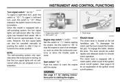
.... EAU00143 Clutch lever The clutch lever is stuck. INSTRUMENT AND CONTROL FUNCTIONS EAU04218 Turn signal switch " / " To signal a right-hand turn signal lights will not selfcancel while you are stopped at the left -hand turn signal lights will self-cancel after it has returned to the center position. Since this model is part of the ignition circuit cut-off system.) Start switch " " Push this switch to crank the engine with a self...
.... EAU00143 Clutch lever The clutch lever is stuck. INSTRUMENT AND CONTROL FUNCTIONS EAU04218 Turn signal switch " / " To signal a right-hand turn signal lights will not selfcancel while you are stopped at the left -hand turn signal lights will self-cancel after it has returned to the center position. Since this model is part of the ignition circuit cut-off system.) Start switch " " Push this switch to crank the engine with a self...
Owners Manual
Page 31
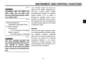
... gal) ECA00102 Your Yamaha engine has been designed to the exhaust system. _ _ 3-8 Use of unleaded fuel will cause severe damage to internal engine parts such as the valves and piston rings, as well as to use of leaded gasoline will extend spark plug life and reduce maintenance costs. INSTRUMENT AND CONTROL FUNCTIONS EAU00185 CAUTION: Immediately wipe off spilled fuel with a pump octane number [(R+M)/2] of...
... gal) ECA00102 Your Yamaha engine has been designed to the exhaust system. _ _ 3-8 Use of unleaded fuel will cause severe damage to internal engine parts such as the valves and piston rings, as well as to use of leaded gasoline will extend spark plug life and reduce maintenance costs. INSTRUMENT AND CONTROL FUNCTIONS EAU00185 CAUTION: Immediately wipe off spilled fuel with a pump octane number [(R+M)/2] of...

Owners Manual
Page 42
... the running engine when the transmission is in gear and the sidestand is moved down . INSTRUMENT AND CONTROL FUNCTIONS EAU00330 Sidestand The sidestand is located on the left side of the ignition circuit cut-off system.) _ _ check this system regularly as described below and have a Yamaha dealer check the system before starting when the transmission is in gear and the clutch lever...
... the running engine when the transmission is in gear and the sidestand is moved down . INSTRUMENT AND CONTROL FUNCTIONS EAU00330 Sidestand The sidestand is located on the left side of the ignition circuit cut-off system.) _ _ check this system regularly as described below and have a Yamaha dealer check the system before starting when the transmission is in gear and the clutch lever...

Owners Manual
Page 46
..., have Yamaha dealer check vehicle. 6-25 4 6-25 6-25 - - 3-19 NOTE: Pre-operation checks should be accomplished in the Pre-operation check list is not working properly, have it inspected and repaired before operating the motorcycle. _ _ 4-2 Correct if necessary. PAGE 6-15, 6-24 6-24 Wheels and tires 6-15-6-17 Brake and shift pedals Brake and clutch levers Sidestand Chassis fasteners Instruments, lights, signals and switches Sidestand switch...
..., have Yamaha dealer check vehicle. 6-25 4 6-25 6-25 - - 3-19 NOTE: Pre-operation checks should be accomplished in the Pre-operation check list is not working properly, have it inspected and repaired before operating the motorcycle. _ _ 4-2 Correct if necessary. PAGE 6-15, 6-24 6-24 Wheels and tires 6-15-6-17 Brake and shift pedals Brake and clutch levers Sidestand Chassis fasteners Instruments, lights, signals and switches Sidestand switch...
Owners Manual
Page 48
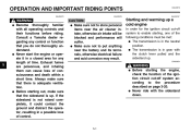
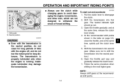
EW000054 _ _ WARNING Before starting the engine, check the function of the ignition circuit cut -off system according to put anything near the air cleaner intake, otherwise air intake will suffer. If the sidestand is in gear with the clutch lever pulled and the sidestand up. G _ CAUTION: G Make sure not to enable starting out, make sure that there is up a cold engine In order for...
EW000054 _ _ WARNING Before starting the engine, check the function of the ignition circuit cut -off system according to put anything near the air cleaner intake, otherwise air intake will suffer. If the sidestand is in gear with the clutch lever pulled and the sidestand up. G _ CAUTION: G Make sure not to enable starting out, make sure that there is up a cold engine In order for...
Owners Manual
Page 49
... oil level warning light flickers or remains on , otherwise have a Yamaha dealer check the electrical circuit. NOTE: If the engine fails to three seconds. Turn the fuel cock lever to " ". 3. Turn the key to "ON" and make sure that the engine stop the engine, and then check the engine oil level and the vehicle for starter (choke) operation.) 5. NOTE: When the transmission is turned to preserve the battery. Turn the starter...
... oil level warning light flickers or remains on , otherwise have a Yamaha dealer check the electrical circuit. NOTE: If the engine fails to three seconds. Turn the fuel cock lever to " ". 3. Turn the key to "ON" and make sure that the engine stop the engine, and then check the engine oil level and the vehicle for starter (choke) operation.) 5. NOTE: When the transmission is turned to preserve the battery. Turn the starter...
Owners Manual
Page 51
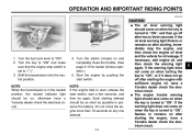
... the transmission. Open the throttle part way and gradually release the clutch lever. 7. Shift the transmission into second gear. (Make sure not to withstand the shock of time with the engine off, and do not tow the motorcycle for long distances. To start out and accelerate 1. OPERATION AND IMPORTANT RIDING POINTS XVS1100A G Always use the clutch while changing gears to avoid damaging the engine, transmission, and drive train...
... the transmission. Open the throttle part way and gradually release the clutch lever. 7. Shift the transmission into second gear. (Make sure not to withstand the shock of time with the engine off, and do not tow the motorcycle for long distances. To start out and accelerate 1. OPERATION AND IMPORTANT RIDING POINTS XVS1100A G Always use the clutch while changing gears to avoid damaging the engine, transmission, and drive train...
Owners Manual
Page 54
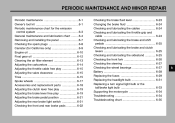
PERIODIC MAINTENANCE AND MINOR REPAIR Periodic maintenance ...6-1 Owner's tool kit ...6-1 Periodic maintenance chart for the emission control system ...6-3 General maintenance and lubrication chart ...6-4 Removing and installing the panel ...6-7 Checking the spark plugs ...6-8 Canister (for California only) ...6-9 Engine oil ...6-10 Final gear oil ...6-12 Cleaning the air filter element ...6-13 Adjusting the carburetors ...6-14 Adjusting the throttle cable free play ...6-15 Adjusting the valve clearance ...6-15 Tires ...6-15 Spoke wheels ...6-17 Accessories and replacement parts...
PERIODIC MAINTENANCE AND MINOR REPAIR Periodic maintenance ...6-1 Owner's tool kit ...6-1 Periodic maintenance chart for the emission control system ...6-3 General maintenance and lubrication chart ...6-4 Removing and installing the panel ...6-7 Checking the spark plugs ...6-8 Canister (for California only) ...6-9 Engine oil ...6-10 Final gear oil ...6-12 Cleaning the air filter element ...6-13 Adjusting the carburetors ...6-14 Adjusting the throttle cable free play ...6-15 Adjusting the valve clearance ...6-15 Tires ...6-15 Spoke wheels ...6-17 Accessories and replacement parts...

Owners Manual
Page 57
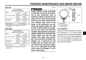
PERIODIC MAINTENANCE AND MINOR REPAIR EAU00471 Periodic maintenance chart for damage. • Replace if necessary. √ √ √ √ √ √ 2 Spark plugs √ Replace. √ Replace. √ 3 * 4 * 5 * 6 * 7 * 8 * 9 * Crankcase ventilation system Fuel line Fuel filter √ √ √ √ √ √ √ √ √ √ √ 6 Exhaust system Carburetor synchronization Idle speed Evaporative emission control system** √ √ √ √ √ √ * Since these items require...
PERIODIC MAINTENANCE AND MINOR REPAIR EAU00471 Periodic maintenance chart for damage. • Replace if necessary. √ √ √ √ √ √ 2 Spark plugs √ Replace. √ Replace. √ 3 * 4 * 5 * 6 * 7 * 8 * 9 * Crankcase ventilation system Fuel line Fuel filter √ √ √ √ √ √ √ √ √ √ √ 6 Exhaust system Carburetor synchronization Idle speed Evaporative emission control system** √ √ √ √ √ √ * Since these items require...

Owners Manual
Page 63
.... Place the spark plug cover in ) 2. PERIODIC MAINTENANCE AND MINOR REPAIR Tightening torque: Spark plug: 20 Nm (2.0 m·kgf, 14.5 ft·lb) NOTE: If a torque wrench is not available when installing a spark plug, a good estimate of the spark plug gasket and its mating surface, and then wipe off any grime from the spark plug threads. 3. However, the spark plug should be tightened to specification. Clean the...
.... Place the spark plug cover in ) 2. PERIODIC MAINTENANCE AND MINOR REPAIR Tightening torque: Spark plug: 20 Nm (2.0 m·kgf, 14.5 ft·lb) NOTE: If a torque wrench is not available when installing a spark plug, a good estimate of the spark plug gasket and its mating surface, and then wipe off any grime from the spark plug threads. 3. However, the spark plug should be tightened to specification. Clean the...
Owners Manual
Page 70
...cm2, 33 psi) 36 psi) 441 lb (200 kg) 90 kg (198 lb)- PERIODIC MAINTENANCE AND MINOR REPAIR XVS1100 Tire air pressure (measured on cold tires) Load* Up to 90 kg (198 lb) Front Rear 225 kPa 225 kPa (2.25 kgf/cm2, (2.25 kgf/cm2, 33 psi) 33 psi)...for this model) does not exceed the maximum load of an overloaded motorcycle could cause tire damage, an accident, or even injury. _ 1. NEVER OVERLOAD YOUR MOTORCYCLE. maximum Maximum load* * Total weight of rider, passenger, cargo and accessories WARNING Proper loading of your motorcycle, such as handling, braking, performance and safety.
...cm2, 33 psi) 36 psi) 441 lb (200 kg) 90 kg (198 lb)- PERIODIC MAINTENANCE AND MINOR REPAIR XVS1100 Tire air pressure (measured on cold tires) Load* Up to 90 kg (198 lb) Front Rear 225 kPa 225 kPa (2.25 kgf/cm2, (2.25 kgf/cm2, 33 psi) 33 psi)...for this model) does not exceed the maximum load of an overloaded motorcycle could cause tire damage, an accident, or even injury. _ 1. NEVER OVERLOAD YOUR MOTORCYCLE. maximum Maximum load* * Total weight of rider, passenger, cargo and accessories WARNING Proper loading of your motorcycle, such as handling, braking, performance and safety.

Owners Manual
Page 75
.... WARNING A soft or spongy feeling in the brake pedal can indicate the presence of air in loss of the footrest as follows. Air in the hydraulic system will diminish the braking performance, which is activated by the brake pedal, is air in direction b. 6-21 PERIODIC MAINTENANCE AND MINOR REPAIR XVS1100 XVS1100A a. Rear brake light switch 2. Periodically check the brake pedal position and, if necessary, have a Yamaha...
.... WARNING A soft or spongy feeling in the brake pedal can indicate the presence of air in loss of the footrest as follows. Air in the hydraulic system will diminish the braking performance, which is activated by the brake pedal, is air in direction b. 6-21 PERIODIC MAINTENANCE AND MINOR REPAIR XVS1100 XVS1100A a. Rear brake light switch 2. Periodically check the brake pedal position and, if necessary, have a Yamaha...

Owners Manual
Page 83
... 2. Fuse box Backup fuse (odometer) Ignition fuse Headlight fuse Carburetor heater fuse Spare fuse (× 3) Signaling system fuse EAU04210 Replacing the fuses The main fuse is located inside the storage compartment. (See page 3-14 for storage compartment cover removal and installation procedures.) 6-29 The fuse box, which contains the fuses for the individual circuits, is located under the ignitor unit panel. Using a conventional battery charger will damage the battery. If...
... 2. Fuse box Backup fuse (odometer) Ignition fuse Headlight fuse Carburetor heater fuse Spare fuse (× 3) Signaling system fuse EAU04210 Replacing the fuses The main fuse is located inside the storage compartment. (See page 3-14 for storage compartment cover removal and installation procedures.) 6-29 The fuse box, which contains the fuses for the individual circuits, is located under the ignitor unit panel. Using a conventional battery charger will damage the battery. If...

Owners Manual
Page 84
... center in question to the electrical system and possibly a fire. _ _ 1. Quick fastener (× 3) If a fuse is blown, replace it as follows. NOTE: Include steps 1-3 and 9-10 only for rider seat removal and installation procedures.) 2. Specified fuses: Main fuse: Backup fuse (odometer): Ignition fuse: Headlight fuse: Carburetor heater fuse: Signaling system fuse: 6-30 6. If the fuse immediately blows again, have a Yamaha dealer check the electrical system. 8. Ignitor unit panel 2. PERIODIC MAINTENANCE AND MINOR REPAIR...
... center in question to the electrical system and possibly a fire. _ _ 1. Quick fastener (× 3) If a fuse is blown, replace it as follows. NOTE: Include steps 1-3 and 9-10 only for rider seat removal and installation procedures.) 2. Specified fuses: Main fuse: Backup fuse (odometer): Ignition fuse: Headlight fuse: Carburetor heater fuse: Signaling system fuse: 6-30 6. If the fuse immediately blows again, have a Yamaha dealer check the electrical system. 8. Ignitor unit panel 2. PERIODIC MAINTENANCE AND MINOR REPAIR...

Owners Manual
Page 101
SPECIFICATIONS Bulb voltage, wattage × quantity Headlight Tail/brake light Front turn signal light Rear turn signal light Meter lighting Oil level warning light Neutral indicator light Turn signal indicator light Engine trouble warning light High beam indicator light Fuses Main fuse Signaling system fuse Backup fuse (odometer) Ignition fuse 30 A 10 A 5A 10 A 15 A 15 A 12 V, 60/55 W × 1 12 V, 8/27 W × 1 12 V, 27/8 W × 2 12 V, 27 W × 2 14 V, 1.4 W × 2 12 V, 1.7 W × 1 12 V, 1.7 W × 1 ...
SPECIFICATIONS Bulb voltage, wattage × quantity Headlight Tail/brake light Front turn signal light Rear turn signal light Meter lighting Oil level warning light Neutral indicator light Turn signal indicator light Engine trouble warning light High beam indicator light Fuses Main fuse Signaling system fuse Backup fuse (odometer) Ignition fuse 30 A 10 A 5A 10 A 15 A 15 A 12 V, 60/55 W × 1 12 V, 8/27 W × 1 12 V, 27/8 W × 2 12 V, 27 W × 2 14 V, 1.4 W × 2 12 V, 1.7 W × 1 12 V, 1.7 W × 1 ...

Owners Manual
Page 113
... fork, checking ...6-26 Fuel ...3-7 Fuel cock...3-9 Fuel tank cap...3-7 Fuses, replacing ...6-29 N Neutral indicator light ...3-2 Noise regulation ...9-4 B Battery ...6-28 Brake and clutch levers, checking and lubricating ...6-25 Brake and shift pedals, checking and lubricating ...6-25 Brake fluid, changing ...6-24 Brake fluid level, checking...6-23 Brake lever...3-5 Brake lever free play, adjusting ...6-19 Brake light switch (rear), adjusting ...6-21 Brake pads, checking...6-22 Brake pedal...3-6 Brake pedal position, adjusting ...6-21 O Oil level warning light ...3-2 P Panel, removing and...
... fork, checking ...6-26 Fuel ...3-7 Fuel cock...3-9 Fuel tank cap...3-7 Fuses, replacing ...6-29 N Neutral indicator light ...3-2 Noise regulation ...9-4 B Battery ...6-28 Brake and clutch levers, checking and lubricating ...6-25 Brake and shift pedals, checking and lubricating ...6-25 Brake fluid, changing ...6-24 Brake fluid level, checking...6-23 Brake lever...3-5 Brake lever free play, adjusting ...6-19 Brake light switch (rear), adjusting ...6-21 Brake pads, checking...6-22 Brake pedal...3-6 Brake pedal position, adjusting ...6-21 O Oil level warning light ...3-2 P Panel, removing and...