

Owners Manual
Page 12
Shifting weights can create unstable handling or slow steering response. Use extreme caution when selecting and installing any large or heavy items to the motorcycle before using it does not in any way reduce ground clearance or cornering clearance, limit suspension travel, steering travel or control operation, or obscure lights or reflectors. 1 1-4 Never attach any accessories. Carefully inspect the accessory before riding...
Shifting weights can create unstable handling or slow steering response. Use extreme caution when selecting and installing any large or heavy items to the motorcycle before using it does not in any way reduce ground clearance or cornering clearance, limit suspension travel, steering travel or control operation, or obscure lights or reflectors. 1 1-4 Never attach any accessories. Carefully inspect the accessory before riding...
Owners Manual
Page 13
... caution when adding electrical accessories. Take care not to aerodynamic effects. If electrical accessories exceed the capacity of the motorcycle's electrical system, an electric failure could result, which could cause a dangerous loss of the motorcycle due to spill any length of consciousness and death within a short time. These accessories may seriously affect the stability of lights or engine power. 1 Gasoline and exhaust gas 1. Always operate...
... caution when adding electrical accessories. Take care not to aerodynamic effects. If electrical accessories exceed the capacity of the motorcycle's electrical system, an electric failure could result, which could cause a dangerous loss of the motorcycle due to spill any length of consciousness and death within a short time. These accessories may seriously affect the stability of lights or engine power. 1 Gasoline and exhaust gas 1. Always operate...

Owners Manual
Page 23
INSTRUMENT AND CONTROL FUNCTIONS Main switch/steering lock ...3-1 Indicator and warning lights ...3-2 Speedometer unit ...3-3 Handlebar switches ...3-3 Clutch lever ...3-4 Shift pedal (XVS1100)...3-5 Shift pedal (XVS1100A) ...3-5 Brake lever ...3-5 Brake pedal ...3-6 Fuel tank cap ...3-7 Fuel ...3-7 Fuel cock ...3-9 Starter (choke) lever ...3-10 Seats (XVS1100) ...3-11 Seats (XVS1100A) ...3-12 Helmet holder ...3-13 Storage compartment ...3-14 Adjusting the shock absorber assembly ...3-15 Luggage strap holders ...3-18 Sidestand ...3-19 Ignition circuit cut-off system ...3-19 3
INSTRUMENT AND CONTROL FUNCTIONS Main switch/steering lock ...3-1 Indicator and warning lights ...3-2 Speedometer unit ...3-3 Handlebar switches ...3-3 Clutch lever ...3-4 Shift pedal (XVS1100)...3-5 Shift pedal (XVS1100A) ...3-5 Brake lever ...3-5 Brake pedal ...3-6 Fuel tank cap ...3-7 Fuel ...3-7 Fuel cock ...3-9 Starter (choke) lever ...3-10 Seats (XVS1100) ...3-11 Seats (XVS1100A) ...3-12 Helmet holder ...3-13 Storage compartment ...3-14 Adjusting the shock absorber assembly ...3-15 Luggage strap holders ...3-18 Sidestand ...3-19 Ignition circuit cut-off system ...3-19 3
Owners Manual
Page 25
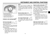
... the engine stop switch to "ON". EAU00063 3 Oil level warning light " " This warning light comes on when the engine oil level is not a malfunction. _ _ EAU03192 EAU00061 1. 2. 3. 4. 5. The electrical circuit of the headlight is pushed to the following procedure. 1. If the warning light does not come on, have a Yamaha dealer check the electrical circuit. Turn the key to " ". 2. INSTRUMENT AND CONTROL FUNCTIONS NOTE: Even if the oil level is sufficient, the warning light...
... the engine stop switch to "ON". EAU00063 3 Oil level warning light " " This warning light comes on when the engine oil level is not a malfunction. _ _ EAU03192 EAU00061 1. 2. 3. 4. 5. The electrical circuit of the headlight is pushed to the following procedure. 1. If the warning light does not come on, have a Yamaha dealer check the electrical circuit. Turn the key to " ". 2. INSTRUMENT AND CONTROL FUNCTIONS NOTE: Even if the oil level is sufficient, the warning light...
Owners Manual
Page 27
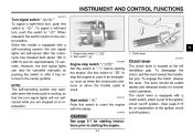
... the ignition circuit cut -off system. (See page 3-19 for approximately 15 seconds. However, the turn signal lights will not selfcancel while you are stopped at the left -hand turn , push this switch to " ". The clutch lever is equipped with a clutch switch, which is stuck. Clutch lever EAU00152 Engine stop switch " / " Set this switch to " " before starting the engine. _ _ 3-4 INSTRUMENT AND CONTROL FUNCTIONS EAU04218 Turn signal switch " / " To signal a right-hand turn...
... the ignition circuit cut -off system. (See page 3-19 for approximately 15 seconds. However, the turn signal lights will not selfcancel while you are stopped at the left -hand turn , push this switch to " ". The clutch lever is equipped with a clutch switch, which is stuck. Clutch lever EAU00152 Engine stop switch " / " Set this switch to " " before starting the engine. _ _ 3-4 INSTRUMENT AND CONTROL FUNCTIONS EAU04218 Turn signal switch " / " To signal a right-hand turn...
Owners Manual
Page 31
... will extend spark plug life and reduce maintenance costs. INSTRUMENT AND CONTROL FUNCTIONS EAU00185 CAUTION: Immediately wipe off spilled fuel with a clean, dry, soft cloth, since fuel may deteriorate painted surfaces or plastic parts. _ _ EAU04194 Recommended fuel: UNLEADED GASOLINE ONLY Fuel tank capacity: Total amount: 17 L (3.74 Imp gal, 4.49 US gal) Reserve amount: 4.5 L (0.99 Imp gal, 1.19 US gal) ECA00102 Your Yamaha engine has...
... will extend spark plug life and reduce maintenance costs. INSTRUMENT AND CONTROL FUNCTIONS EAU00185 CAUTION: Immediately wipe off spilled fuel with a clean, dry, soft cloth, since fuel may deteriorate painted surfaces or plastic parts. _ _ EAU04194 Recommended fuel: UNLEADED GASOLINE ONLY Fuel tank capacity: Total amount: 17 L (3.74 Imp gal, 4.49 US gal) Reserve amount: 4.5 L (0.99 Imp gal, 1.19 US gal) ECA00102 Your Yamaha engine has...
Owners Manual
Page 42
INSTRUMENT AND CONTROL FUNCTIONS EAU00330 Sidestand The sidestand is located on the left side of the ignition circuit cut-off system.) _ _ check this system regularly as described below and have a Yamaha dealer check the system before starting off. G It cuts the running engine when the transmission is in gear and the sidestand is noted, have a Yamaha dealer repair it if it with...
INSTRUMENT AND CONTROL FUNCTIONS EAU00330 Sidestand The sidestand is located on the left side of the ignition circuit cut-off system.) _ _ check this system regularly as described below and have a Yamaha dealer check the system before starting off. G It cuts the running engine when the transmission is in gear and the sidestand is noted, have a Yamaha dealer repair it if it with...

Owners Manual
Page 46
... inspection can be made each time the motorcycle is smooth. • Lubricate if necessary Check for damage. Check tire condition and tread depth. Check air pressure. and the added safety it assures is not working properly, have it inspected and repaired before operating the motorcycle. _ _ 4-2 Correct if necessary. PRE-OPERATION CHECKS ITEM Throttle grip Control cables CHECKS • Make sure...
... inspection can be made each time the motorcycle is smooth. • Lubricate if necessary Check for damage. Check tire condition and tread depth. Check air pressure. and the added safety it assures is not working properly, have it inspected and repaired before operating the motorcycle. _ _ 4-2 Correct if necessary. PRE-OPERATION CHECKS ITEM Throttle grip Control cables CHECKS • Make sure...
Owners Manual
Page 48
... performance will suffer. 5- G Never start the engine or operate it could contact the ground and distract the operator, resulting in gear with the clutch lever pulled and the sidestand up . G Before starting the engine, check the function of the ignition circuit cut -off system according to enable starting, one of consciousness and death within a short time. Consult a Yamaha dealer regarding any length of control...
... performance will suffer. 5- G Never start the engine or operate it could contact the ground and distract the operator, resulting in gear with the clutch lever pulled and the sidestand up . G Before starting the engine, check the function of the ignition circuit cut -off system according to enable starting, one of consciousness and death within a short time. Consult a Yamaha dealer regarding any length of control...

Owners Manual
Page 49
... go off after starting the engine with sufficient engine oil, have a Yamaha dealer check the electrical circuit. 5 5-2 _ G The engine trouble warning light should be on when the key is turned to start, release the start switch. Turn the fuel cock lever to "ON". Start the engine by pushing the start switch, wait a few seconds, and then try again. Shift the transmission into the neutral position. Turn the starter (choke) on when the key is set to...
... go off after starting the engine with sufficient engine oil, have a Yamaha dealer check the electrical circuit. 5 5-2 _ G The engine trouble warning light should be on when the key is turned to start, release the start switch. Turn the fuel cock lever to "ON". Start the engine by pushing the start switch, wait a few seconds, and then try again. Shift the transmission into the neutral position. Turn the starter (choke) on when the key is set to...
Owners Manual
Page 51
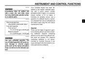
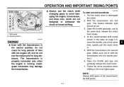
To start out and accelerate 1. Open the throttle part way and gradually release the clutch lever. 7. OPERATION AND IMPORTANT RIDING POINTS XVS1100A G Always use the clutch while changing gears to avoid damaging the engine, transmission, and drive train, which are not designed to withstand the shock of time with the transmission in . 5. EAU02988 _ 1. Neutral position EC000048 _ CAUTION: G Even with the engine off, and do not...
To start out and accelerate 1. Open the throttle part way and gradually release the clutch lever. 7. OPERATION AND IMPORTANT RIDING POINTS XVS1100A G Always use the clutch while changing gears to avoid damaging the engine, transmission, and drive train, which are not designed to withstand the shock of time with the transmission in . 5. EAU02988 _ 1. Neutral position EC000048 _ CAUTION: G Even with the engine off, and do not...
Owners Manual
Page 54
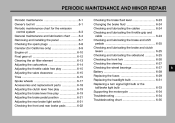
PERIODIC MAINTENANCE AND MINOR REPAIR Periodic maintenance ...6-1 Owner's tool kit ...6-1 Periodic maintenance chart for the emission control system ...6-3 General maintenance and lubrication chart ...6-4 Removing and installing the panel ...6-7 Checking the spark plugs ...6-8 Canister (for California only) ...6-9 Engine oil ...6-10 Final gear oil ...6-12 Cleaning the air filter element ...6-13 Adjusting the carburetors ...6-14 Adjusting the throttle cable free play ...6-15 Adjusting the valve clearance ...6-15 Tires ...6-15 Spoke wheels ...6-17 Accessories and replacement parts...
PERIODIC MAINTENANCE AND MINOR REPAIR Periodic maintenance ...6-1 Owner's tool kit ...6-1 Periodic maintenance chart for the emission control system ...6-3 General maintenance and lubrication chart ...6-4 Removing and installing the panel ...6-7 Checking the spark plugs ...6-8 Canister (for California only) ...6-9 Engine oil ...6-10 Final gear oil ...6-12 Cleaning the air filter element ...6-13 Adjusting the carburetors ...6-14 Adjusting the throttle cable free play ...6-15 Adjusting the valve clearance ...6-15 Tires ...6-15 Spoke wheels ...6-17 Accessories and replacement parts...
Owners Manual
Page 57
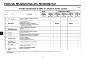
PERIODIC MAINTENANCE AND MINOR REPAIR EAU00471 Periodic maintenance chart for damage. • Replace if necessary. √ √ √ √ √ √ 2 Spark plugs √ Replace. √ Replace. √ 3 * 4 * 5 * 6 * 7 * 8 * 9 * Crankcase ventilation system Fuel line Fuel filter √ √ √ √ √ √ √ √ √ √ √ 6 Exhaust system Carburetor synchronization Idle speed Evaporative emission control system** √ √ √ √ √ √ * Since these items require...
PERIODIC MAINTENANCE AND MINOR REPAIR EAU00471 Periodic maintenance chart for damage. • Replace if necessary. √ √ √ √ √ √ 2 Spark plugs √ Replace. √ Replace. √ 3 * 4 * 5 * 6 * 7 * 8 * 9 * Crankcase ventilation system Fuel line Fuel filter √ √ √ √ √ √ √ √ √ √ √ 6 Exhaust system Carburetor synchronization Idle speed Evaporative emission control system** √ √ √ √ √ √ * Since these items require...

Owners Manual
Page 63
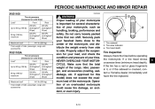
... as possible. _ _ a. G Check each hose and canister for California only) This model is equipped with the spark plug wrench, and then tighten it if necessary. 4. G Check each hose connection. Spark plug gap: 0.7-0.8 mm (0.028-0.031 in the original position. 6-9 Spark plug gap 6 To install a spark plug 1. Install the spark plug with a canister to specification. PERIODIC MAINTENANCE AND MINOR REPAIR Tightening torque: Spark plug: 20 Nm (2.0 m·kgf, 14...
... as possible. _ _ a. G Check each hose and canister for California only) This model is equipped with the spark plug wrench, and then tighten it if necessary. 4. G Check each hose connection. Spark plug gap: 0.7-0.8 mm (0.028-0.031 in the original position. 6-9 Spark plug gap 6 To install a spark plug 1. Install the spark plug with a canister to specification. PERIODIC MAINTENANCE AND MINOR REPAIR Tightening torque: Spark plug: 20 Nm (2.0 m·kgf, 14...
Owners Manual
Page 70
... sure that can shift. Tire wear indicator a. Securely pack your motorcycle, such as handling, braking, performance and safety. Properly adjust the suspension for this model) does not exceed the maximum load of your heaviest items close to side. Tire tread depth Tire inspection Always check the tires before operating the motorcycle. Operation of rider, passenger, cargo and accessories XVS1100A Tire air pressure (measured on cold tires) Load* Up...
... sure that can shift. Tire wear indicator a. Securely pack your motorcycle, such as handling, braking, performance and safety. Properly adjust the suspension for this model) does not exceed the maximum load of your heaviest items close to side. Tire tread depth Tire inspection Always check the tires before operating the motorcycle. Operation of rider, passenger, cargo and accessories XVS1100A Tire air pressure (measured on cold tires) Load* Up...

Owners Manual
Page 75
... the braking performance, which is activated by the brake pedal, is air in the hydraulic system. To make the brake light come on earlier, turn the adjusting nut in loss of the footrest as follows. To make the brake light come on just before operating the motorcycle. PERIODIC MAINTENANCE AND MINOR REPAIR XVS1100 XVS1100A a. If necessary, adjust the brake light switch as shown. Rear brake light switch adjusting...
... the braking performance, which is activated by the brake pedal, is air in the hydraulic system. To make the brake light come on earlier, turn the adjusting nut in loss of the footrest as follows. To make the brake light come on just before operating the motorcycle. PERIODIC MAINTENANCE AND MINOR REPAIR XVS1100 XVS1100A a. If necessary, adjust the brake light switch as shown. Rear brake light switch adjusting...

Owners Manual
Page 83
... battery. Positive terminal 2. Storing a discharged battery can cause permanent battery damage. PERIODIC MAINTENANCE AND MINOR REPAIR EC000102 _ 1. Negative terminal 4. The fuse box, which contains the fuses for the individual circuits, is required. If you do not have access to the battery terminals. 6 _ CAUTION: keep the battery G Always charged. Fuse box Backup fuse (odometer) Ignition fuse Headlight fuse Carburetor heater fuse Spare fuse (× 3) Signaling system fuse EAU04210 Replacing the fuses The main fuse...
... battery. Positive terminal 2. Storing a discharged battery can cause permanent battery damage. PERIODIC MAINTENANCE AND MINOR REPAIR EC000102 _ 1. Negative terminal 4. The fuse box, which contains the fuses for the individual circuits, is required. If you do not have access to the battery terminals. 6 _ CAUTION: keep the battery G Always charged. Fuse box Backup fuse (odometer) Ignition fuse Headlight fuse Carburetor heater fuse Spare fuse (× 3) Signaling system fuse EAU04210 Replacing the fuses The main fuse...

Owners Manual
Page 84
... ignitor unit panel outward to the electrical system and possibly a fire. _ _ 1. NOTE: Include steps 1-3 and 9-10 only for rider seat removal and installation procedures.) 2. Specified fuses: Main fuse: Backup fuse (odometer): Ignition fuse: Headlight fuse: Carburetor heater fuse: Signaling system fuse: 6-30 6. Spare main fuse 3. Install the storage compartment cover. 6 30 A 5A 10 A 15 A 15 A 10 A Remove the blown fuse, and then install a new fuse of a higher amperage rating than...
... ignitor unit panel outward to the electrical system and possibly a fire. _ _ 1. NOTE: Include steps 1-3 and 9-10 only for rider seat removal and installation procedures.) 2. Specified fuses: Main fuse: Backup fuse (odometer): Ignition fuse: Headlight fuse: Carburetor heater fuse: Signaling system fuse: 6-30 6. Spare main fuse 3. Install the storage compartment cover. 6 30 A 5A 10 A 15 A 15 A 10 A Remove the blown fuse, and then install a new fuse of a higher amperage rating than...

Owners Manual
Page 101
SPECIFICATIONS Bulb voltage, wattage × quantity Headlight Tail/brake light Front turn signal light Rear turn signal light Meter lighting Oil level warning light Neutral indicator light Turn signal indicator light Engine trouble warning light High beam indicator light Fuses Main fuse Signaling system fuse Backup fuse (odometer) Ignition fuse 30 A 10 A 5A 10 A 15 A 15 A 12 V, 60/55 W × 1 12 V, 8/27 W × 1 12 V, 27/8 W × 2 12 V, 27 W × 2 14 V, 1.4 W × 2 12 V, 1.7 W × 1 12 V, 1.7 W × 1 ...
SPECIFICATIONS Bulb voltage, wattage × quantity Headlight Tail/brake light Front turn signal light Rear turn signal light Meter lighting Oil level warning light Neutral indicator light Turn signal indicator light Engine trouble warning light High beam indicator light Fuses Main fuse Signaling system fuse Backup fuse (odometer) Ignition fuse 30 A 10 A 5A 10 A 15 A 15 A 12 V, 60/55 W × 1 12 V, 8/27 W × 1 12 V, 27/8 W × 2 12 V, 27 W × 2 14 V, 1.4 W × 2 12 V, 1.7 W × 1 12 V, 1.7 W × 1 ...

Owners Manual
Page 113
... fork, checking ...6-26 Fuel ...3-7 Fuel cock...3-9 Fuel tank cap...3-7 Fuses, replacing ...6-29 N Neutral indicator light ...3-2 Noise regulation ...9-4 B Battery ...6-28 Brake and clutch levers, checking and lubricating ...6-25 Brake and shift pedals, checking and lubricating ...6-25 Brake fluid, changing ...6-24 Brake fluid level, checking...6-23 Brake lever...3-5 Brake lever free play, adjusting ...6-19 Brake light switch (rear), adjusting ...6-21 Brake pads, checking...6-22 Brake pedal...3-6 Brake pedal position, adjusting ...6-21 O Oil level warning light ...3-2 P Panel, removing and...
... fork, checking ...6-26 Fuel ...3-7 Fuel cock...3-9 Fuel tank cap...3-7 Fuses, replacing ...6-29 N Neutral indicator light ...3-2 Noise regulation ...9-4 B Battery ...6-28 Brake and clutch levers, checking and lubricating ...6-25 Brake and shift pedals, checking and lubricating ...6-25 Brake fluid, changing ...6-24 Brake fluid level, checking...6-23 Brake lever...3-5 Brake lever free play, adjusting ...6-19 Brake light switch (rear), adjusting ...6-21 Brake pads, checking...6-22 Brake pedal...3-6 Brake pedal position, adjusting ...6-21 O Oil level warning light ...3-2 P Panel, removing and...