
Owners Manual
Page 36
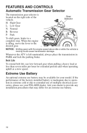
... shift gears, brake to provide any installation procedures that may be available for extended periods and when operating uphill at a slow speed. Whenever the ATV is moving could cause transmission damage. When the engine is idling, move the lever to extended use battery. 34 FEATURES AND CONTROLS Automatic Transmission Gear Selector The transmission gear selector is inadequate due to operation in PARK and lock the parking brake. If the performance of the factory...
... shift gears, brake to provide any installation procedures that may be available for extended periods and when operating uphill at a slow speed. Whenever the ATV is moving could cause transmission damage. When the engine is idling, move the lever to extended use battery. 34 FEATURES AND CONTROLS Automatic Transmission Gear Selector The transmission gear selector is inadequate due to operation in PARK and lock the parking brake. If the performance of the factory...

Owners Manual
Page 37
... 4X4, the demand drive unit Switch will automatically disengage. When the rear wheels regain traction, the demand drive unit will automatically engage any time the rear wheels lose traction. If the rear wheels are at all times. NOTICE: Switching to 4X4. Always switch to 4X4 while the rear wheels have traction or are spinning, release the throttle before getting into conditions where front wheel drive may cause severe drive shaft and gearcase damage...
... 4X4, the demand drive unit Switch will automatically disengage. When the rear wheels regain traction, the demand drive unit will automatically engage any time the rear wheels lose traction. If the rear wheels are at all times. NOTICE: Switching to 4X4. Always switch to 4X4 while the rear wheels have traction or are spinning, release the throttle before getting into conditions where front wheel drive may cause severe drive shaft and gearcase damage...
Owners Manual
Page 39
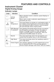
... operate the ATV if this warning appears. If the indicator stops flashing but remains illuminated, the overheating condition remains, and the system will automatically reduce engine power. Check Engine This indicator appears if an EFI-related fault occurs. See your authorized POLARIS dealer for service. FEATURES AND CONTROLS Instrument Cluster Digital/Analog Gauge Indicator Lamps Lamp Indicates Vehicle Speed Over Temperature Condition When standard mode is selected...
... operate the ATV if this warning appears. If the indicator stops flashing but remains illuminated, the overheating condition remains, and the system will automatically reduce engine power. Check Engine This indicator appears if an EFI-related fault occurs. See your authorized POLARIS dealer for service. FEATURES AND CONTROLS Instrument Cluster Digital/Analog Gauge Indicator Lamps Lamp Indicates Vehicle Speed Over Temperature Condition When standard mode is selected...

Owners Manual
Page 41
... reached. Gear Display - See page 41 for resetting instructions. 6. 4X4 Display - Refuel immediately. The time will flash. The clock displays time in the fuel tank. All segments including the fuel icon will display for scheduled maintenance. Information Display - Service Reminder Display - See page 41 for resetting instructions. 5. Fuel Gauge Display - See your dealer for 5-10 seconds. FEATURES AND CONTROLS Instrument Cluster Digital/Analog Gauge Rider Information Center 1.
... reached. Gear Display - See page 41 for resetting instructions. 6. 4X4 Display - Refuel immediately. The time will flash. The clock displays time in the fuel tank. All segments including the fuel icon will display for scheduled maintenance. Information Display - Service Reminder Display - See page 41 for resetting instructions. 5. Fuel Gauge Display - See your dealer for 5-10 seconds. FEATURES AND CONTROLS Instrument Cluster Digital/Analog Gauge Rider Information Center 1.

Owners Manual
Page 50
FEATURES AND CONTROLS Instrument Cluster Diagnostic Display Code Definitions Diagnostic Codes Component Throttle Body Control - Hardware Disruption Idle Fuel Correction Bank 1 Condition Condition Exists Condition Exists Condition Exists Condition Exists Condition Exists Condition Exists Condition Exists Condition Exists Condition Exists Condition Exists Condition Exists Data Valid But Above Normal Operating Range - Least Severe Data Valid But Below Normal Operating Range - Least Severe Current Above Normal Or Grounded Circuit Current Above Normal Or Grounded Circuit Condition ...
FEATURES AND CONTROLS Instrument Cluster Diagnostic Display Code Definitions Diagnostic Codes Component Throttle Body Control - Hardware Disruption Idle Fuel Correction Bank 1 Condition Condition Exists Condition Exists Condition Exists Condition Exists Condition Exists Condition Exists Condition Exists Condition Exists Condition Exists Condition Exists Condition Exists Data Valid But Above Normal Operating Range - Least Severe Data Valid But Below Normal Operating Range - Least Severe Current Above Normal Or Grounded Circuit Current Above Normal Or Grounded Circuit Condition ...
Owners Manual
Page 51
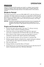
... engine and drive components will damage close-fitted engine parts and drive components. See page 90. Vary the throttle positions. Always exercise extreme caution whenever handling gasoline. 2. Drive slowly at sustained idle. 5. Do not operate at first. Perform regular checks on fluid levels, controls and areas outlined on the dipstick. Pull only light loads. 7. Change both the oil and the filter at full throttle or high speeds...
... engine and drive components will damage close-fitted engine parts and drive components. See page 90. Vary the throttle positions. Always exercise extreme caution whenever handling gasoline. 2. Drive slowly at sustained idle. 5. Do not operate at first. Perform regular checks on fluid levels, controls and areas outlined on the dipstick. Pull only light loads. 7. Change both the oil and the filter at full throttle or high speeds...

Owners Manual
Page 69
... and the load on the racks raises the center of gravity of the vehicle. NEVER EXCEED THE MAXIMUM WEIGHT CAPACITY of the vehicle and creates a less stable operating condition. When operating over the rack sides. HEAVY LOADS CAN CAUSE BRAKING AND CONTROL PROBLEMS. Use extreme caution when applying brakes with loads that extend over rough or hilly terrain, reduce speed and cargo to the...
... and the load on the racks raises the center of gravity of the vehicle. NEVER EXCEED THE MAXIMUM WEIGHT CAPACITY of the vehicle and creates a less stable operating condition. When operating over the rack sides. HEAVY LOADS CAN CAUSE BRAKING AND CONTROL PROBLEMS. Use extreme caution when applying brakes with loads that extend over rough or hilly terrain, reduce speed and cargo to the...

Owners Manual
Page 70
..., reduce speed and cargo weight to extend belt life. 8. Use low forward gear when hauling or towing heavy cargo to maintain stable driving conditions. 6. OPERATION Hauling Cargo 1. Do not obstruct the headlight beam with extreme caution whenever hauling or towing loads. Never exceed the weight capacities specified for 2/3 your ATV on the rear rack) and mounted as low as possible. 3. Always operate the vehicle with cargo...
..., reduce speed and cargo weight to extend belt life. 8. Use low forward gear when hauling or towing heavy cargo to maintain stable driving conditions. 6. OPERATION Hauling Cargo 1. Do not obstruct the headlight beam with extreme caution whenever hauling or towing loads. Never exceed the weight capacities specified for 2/3 your ATV on the rear rack) and mounted as low as possible. 3. Always operate the vehicle with cargo...
Owners Manual
Page 89
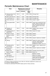
... Ź Radiator (if applicable) Ź Cooling hoses (if applicable) Ź Engine mounts Exhaust muffler/ pipe D Spark plug E Ź Wiring 100 H 100 H 100 H 100 H 100 H 100 H 12 M 12 M 12 M 12 M 12 M 12 M D Clutches (drive and driven) D Front wheel bearings D Brake fluid Spark arrester Ź Coolant Idle speed D Toe adjustment Headlight aim 100 H 100 H 200 H 300 H - 12 M 12 M 24 M 36 M 60 M - Ź Perform these services. 87 apply dielectric grease to connectors subjected to pressurize fuel pump; replace worn parts...
... Ź Radiator (if applicable) Ź Cooling hoses (if applicable) Ź Engine mounts Exhaust muffler/ pipe D Spark plug E Ź Wiring 100 H 100 H 100 H 100 H 100 H 100 H 12 M 12 M 12 M 12 M 12 M 12 M D Clutches (drive and driven) D Front wheel bearings D Brake fluid Spark arrester Ź Coolant Idle speed D Toe adjustment Headlight aim 100 H 100 H 200 H 300 H - 12 M 12 M 24 M 36 M 60 M - Ź Perform these services. 87 apply dielectric grease to connectors subjected to pressurize fuel pump; replace worn parts...

Owners Manual
Page 106
... wheel on the hub with the valve stem toward the outside and rotation arrows on the tire pointing toward forward rotation. 4. MAINTENANCE Tires Wheel Installation 1. Lock the parking brake. 3. Place the transmission in an accident or rollover. Install the wheel nuts and finger-tighten them. 5. Nut Type Lug Nut (Aluminum Wheels) Nut Torque 30 ft-lbs (41 Nm) PLUS 1/4 TURN 2-Piece Flange Nut (Steel Wheels...
... wheel on the hub with the valve stem toward the outside and rotation arrows on the tire pointing toward forward rotation. 4. MAINTENANCE Tires Wheel Installation 1. Lock the parking brake. 3. Place the transmission in an accident or rollover. Install the wheel nuts and finger-tighten them. 5. Nut Type Lug Nut (Aluminum Wheels) Nut Torque 30 ft-lbs (41 Nm) PLUS 1/4 TURN 2-Piece Flange Nut (Steel Wheels...

Owners Manual
Page 110
... two screws on the lower front corners of the lamp. 1. Oil from the rear of the pod. 4. Turn the lamp counter-clockwise to remove it. 7. Unplug the headlamp from the speedometer. Headlight Lamp Replacement When servicing a halogen lamp, don't touch the lamp with bare fingers. Lift the pod cover and disconnect the speedometer harnesses from the wiring harness. MAINTENANCE Lights Poor lighting can cause burns...
... two screws on the lower front corners of the lamp. 1. Oil from the rear of the pod. 4. Turn the lamp counter-clockwise to remove it. 7. Unplug the headlamp from the speedometer. Headlight Lamp Replacement When servicing a halogen lamp, don't touch the lamp with bare fingers. Lift the pod cover and disconnect the speedometer harnesses from the wiring harness. MAINTENANCE Lights Poor lighting can cause burns...

Owners Manual
Page 112
... out of the headlight pod. 2. Lift the pod cover and disconnect the speedometer harnesses from the wiring harness. 5. The distance from the headlight mounting tabs. 6. Use a small screwdriver to remove the o-rings from the headlamp parting line to install the new housing and reassemble the pod. MAINTENANCE Lights Headlight Housing Replacement 1. Lift the pod slightly while depressing the tabs at the rear of the...
... out of the headlight pod. 2. Lift the pod cover and disconnect the speedometer harnesses from the wiring harness. 5. The distance from the headlight mounting tabs. 6. Use a small screwdriver to remove the o-rings from the headlamp parting line to install the new housing and reassemble the pod. MAINTENANCE Lights Headlight Housing Replacement 1. Lift the pod slightly while depressing the tabs at the rear of the...

Owners Manual
Page 113
... Taillight Socket Lamp 111 Reinstall the harness connector. 5. MAINTENANCE Lights Lower Headlamp Replacement 1. Reinstall the harness assembly into the headlight assembly. 4. Phillips Screw Lamp Harness Taillight/Brakelight Lamp Replacement 1. Apply dielectric grease to remove it. 3. Turn the back of the headlight harness counter-clockwise and pull the harness assembly away from the back of the light assembly. 2. Test the light for proper operation. Turn the headlight harness clockwise to secure the headlamp...
... Taillight Socket Lamp 111 Reinstall the harness connector. 5. MAINTENANCE Lights Lower Headlamp Replacement 1. Reinstall the harness assembly into the headlight assembly. 4. Phillips Screw Lamp Harness Taillight/Brakelight Lamp Replacement 1. Apply dielectric grease to remove it. 3. Turn the back of the headlight harness counter-clockwise and pull the harness assembly away from the back of the light assembly. 2. Test the light for proper operation. Turn the headlight harness clockwise to secure the headlamp...

Owners Manual
Page 130
Replacement safety labels are provided by POLARIS at the following items: • Wheel bearings • Radiator • Transmission seals • Brakes • Cab and body panels • Electrical components • Switches and controls • Labels If an informational or graphic label becomes illegible or comes off, contact your POLARIS dealer to purchase a replacement. Follow the instructions on your vehicle. • Always use of your POLARIS vehicle. Grease all zerk fittings...
Replacement safety labels are provided by POLARIS at the following items: • Wheel bearings • Radiator • Transmission seals • Brakes • Cab and body panels • Electrical components • Switches and controls • Labels If an informational or graphic label becomes illegible or comes off, contact your POLARIS dealer to purchase a replacement. Follow the instructions on your vehicle. • Always use of your POLARIS vehicle. Grease all zerk fittings...

Owners Manual
Page 133
... to specification. 3. MAINTENANCE Cleaning and Storage Storage Tips Fluid Levels Inspect the fluid levels. After stabilizing the fuel, remove the spark plugs and add 2-3 tablespoons of the spark plug cap and reinstall the caps onto the plugs. 4. To access the plug holes, use a section of clear 1/4" hose and a small plastic squeeze bottle filled with a protective film of gasoline. 131 Turn the engine over several times using electric start. Oil will...
... to specification. 3. MAINTENANCE Cleaning and Storage Storage Tips Fluid Levels Inspect the fluid levels. After stabilizing the fuel, remove the spark plugs and add 2-3 tablespoons of the spark plug cap and reinstall the caps onto the plugs. 4. To access the plug holes, use a section of clear 1/4" hose and a small plastic squeeze bottle filled with a protective film of gasoline. 131 Turn the engine over several times using electric start. Oil will...
Owners Manual
Page 140
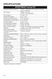
SPECIFICATIONS SPORTSMAN Touring 570 Maximum Weight Capacity Dry Weight Fuel Capacity Engine Oil Capacity Transmission Oil Capacity Demand Drive Fluid Capacity Coolant Capacity Front Rack/Box Capacity Rear Rack/Box Capacity Receiver Hitch Tongue Capacity Hitch Towing Rating Unbraked Trailer Towing Capacity* Overall Length/Width/Height Wheelbase Ground Clearance Minimum Turning Radius Engine Displacement Bore x Stroke Alternator Output Compression Ratio Starting System Fuel System Ignition System Spark Plug / Gap Lubrication System Driving System Type Front Suspension Rear Suspension Shift Type...
SPECIFICATIONS SPORTSMAN Touring 570 Maximum Weight Capacity Dry Weight Fuel Capacity Engine Oil Capacity Transmission Oil Capacity Demand Drive Fluid Capacity Coolant Capacity Front Rack/Box Capacity Rear Rack/Box Capacity Receiver Hitch Tongue Capacity Hitch Towing Rating Unbraked Trailer Towing Capacity* Overall Length/Width/Height Wheelbase Ground Clearance Minimum Turning Radius Engine Displacement Bore x Stroke Alternator Output Compression Ratio Starting System Fuel System Ignition System Spark Plug / Gap Lubrication System Driving System Type Front Suspension Rear Suspension Shift Type...

Owners Manual
Page 146
... product under your name and address with a local POLARIS dealer in your country to a POLARIS Servicing Dealer. WARRANTY How To Obtain Warranty Service If your vehicle requires warranty service, you must take your product to perform the warranty repair. Outside the Country where your product was purchased: ... from any POLARIS Servicing Dealer to Safety Bulletins. 144 You may be authorized to an authorized POLARIS dealer. If you purchase from a private party: If you purchase a POLARIS product from POLARIS in order to determine this product's warranty or service coverage if ...
... product under your name and address with a local POLARIS dealer in your country to a POLARIS Servicing Dealer. WARRANTY How To Obtain Warranty Service If your vehicle requires warranty service, you must take your product to perform the warranty repair. Outside the Country where your product was purchased: ... from any POLARIS Servicing Dealer to Safety Bulletins. 144 You may be authorized to an authorized POLARIS dealer. If you purchase from a private party: If you purchase a POLARIS product from POLARIS in order to determine this product's warranty or service coverage if ...

Owners Manual
Page 148
... POLARIS standard limited warranty for at the time it covers components of the vehicle owner. The warranty period for ATVs less than 100cc emissions-certified vehicles starts on the date of purchase by original retail purchaser and continues for evaporative emissions: Fuel Tank Fuel Cap Fuel Line Fuel Line Fittings Clamps* Pressure Relief Valves* Control Valves* Control Solenoids* Electronic Controls Vacuum Control Diaphragms* Control Cables* Control Linkages* Purge Valves Vapor Hoses Liquid/Vapor Separator Carbon Canister Canister Mounting...
... POLARIS standard limited warranty for at the time it covers components of the vehicle owner. The warranty period for ATVs less than 100cc emissions-certified vehicles starts on the date of purchase by original retail purchaser and continues for evaporative emissions: Fuel Tank Fuel Cap Fuel Line Fuel Line Fittings Clamps* Pressure Relief Valves* Control Valves* Control Solenoids* Electronic Controls Vacuum Control Diaphragms* Control Cables* Control Linkages* Purge Valves Vapor Hoses Liquid/Vapor Separator Carbon Canister Canister Mounting...

Owners Manual
Page 155
... Footwell Support Removal ...102 Fuel Recommendations...33 Fuel Safety ...11 Fuel Tank Cap...33 Fuse Replacement ...107 M Maintenance Chart ...84-87 Master Cylinder ...30 Metric Display ...40 Mode Switch ...26 Modifications ...9 N Noise Emission Control System ...83 G Gasoline Handling ...11 Gauge, Code Definitions...44-48 Gauge, Digital/Analog ...36-43 Gear Selector...34 Gloves ...9 O Oil Engine ...89-92 Transmission ...93-94 Oil and Filter Change ...91-92 Oil Change Transmission ...94 Oil Level Engine ...90 Transmission ...94 Oil Recommendations ...89 Operation on...
... Footwell Support Removal ...102 Fuel Recommendations...33 Fuel Safety ...11 Fuel Tank Cap...33 Fuse Replacement ...107 M Maintenance Chart ...84-87 Master Cylinder ...30 Metric Display ...40 Mode Switch ...26 Modifications ...9 N Noise Emission Control System ...83 G Gasoline Handling ...11 Gauge, Code Definitions...44-48 Gauge, Digital/Analog ...36-43 Gear Selector...34 Gloves ...9 O Oil Engine ...89-92 Transmission ...93-94 Oil and Filter Change ...91-92 Oil Change Transmission ...94 Oil Level Engine ...90 Transmission ...94 Oil Recommendations ...89 Operation on...

Owners Manual
Page 156
... Side Panel Removal...101 Sidehilling ...60 Signal Words ...4 Spark Arrester ...115 Spark Plug Inspection ...112-113 Spark Plug Recommendations...112 Spark Plug Torque Specification . . 112 Spark Plugs ...112-113 Specifications...138-139 Speedometer ...36 Spring Adjustment, Rear Shock . . 125 Starting the Engine ...53 Steering Assembly ...100 Storage ...127-132 Storage Tips ...130-132 Switches 4X4 Switch ...35 Engine Stop Switch...27 Headlight Switch...27 Main Key Switch ...27 Mode/Reverse Override Switch . 26 T Taillight Lamp Replacement ...111 Throttle Body Adjustment ...126 Throttle Cable...
... Side Panel Removal...101 Sidehilling ...60 Signal Words ...4 Spark Arrester ...115 Spark Plug Inspection ...112-113 Spark Plug Recommendations...112 Spark Plug Torque Specification . . 112 Spark Plugs ...112-113 Specifications...138-139 Speedometer ...36 Spring Adjustment, Rear Shock . . 125 Starting the Engine ...53 Steering Assembly ...100 Storage ...127-132 Storage Tips ...130-132 Switches 4X4 Switch ...35 Engine Stop Switch...27 Headlight Switch...27 Main Key Switch ...27 Mode/Reverse Override Switch . 26 T Taillight Lamp Replacement ...111 Throttle Body Adjustment ...126 Throttle Cable...