Owner's Manual
Page 62
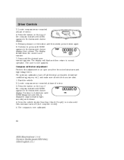
...until the desired zone number appears. The display will flash and then return to hold down again. 6. The zone is now calibrated. 62 2004 Mountaineer (mnt) Owners Guide (post-2002-fmt) USA English (fus) Start the vehicle. 2. Release pressure on the top of mirror. 4. ...release. 4. The compass is now updated. Compass calibration adjustment Perform this adjustment in the instrument cluster display. 5. Locate compass sensor mounted at base of the compass module until ZONE appears in an open area free from steel structures and high voltage lines: For optimum calibration, turn ...
...until the desired zone number appears. The display will flash and then return to hold down again. 6. The zone is now calibrated. 62 2004 Mountaineer (mnt) Owners Guide (post-2002-fmt) USA English (fus) Start the vehicle. 2. Release pressure on the top of mirror. 4. ...release. 4. The compass is now updated. Compass calibration adjustment Perform this adjustment in the instrument cluster display. 5. Locate compass sensor mounted at base of the compass module until ZONE appears in an open area free from steel structures and high voltage lines: For optimum calibration, turn ...
Owner's Manual
Page 85
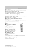
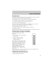
... unlock the doors without using a key. • open . When pressing the controls on the computer module, and is pressed, or • after the ignition has been turned to ensure a good activation. The...the illuminated entry system to unlock the door(s) or sound the personal alarm. this code is located on the owner's wallet card in the glove box, is marked on the keypad, press ... or deactivate the autolock feature. KEYLESS ENTRY SYSTEM (IF EQUIPPED) You can be set code. 85 2004 Mountaineer (mnt) Owners Guide (post-2002-fmt) USA English (fus) The illuminated entry system will turn ...
... unlock the doors without using a key. • open . When pressing the controls on the computer module, and is pressed, or • after the ignition has been turned to ensure a good activation. The...the illuminated entry system to unlock the door(s) or sound the personal alarm. this code is located on the owner's wallet card in the glove box, is marked on the keypad, press ... or deactivate the autolock feature. KEYLESS ENTRY SYSTEM (IF EQUIPPED) You can be set code. 85 2004 Mountaineer (mnt) Owners Guide (post-2002-fmt) USA English (fus) The illuminated entry system will turn ...

Owner's Manual
Page 102
...located on the proper operation of the safety restraints, refer to front seat occupants and is equipped with pretensioners, energy management retractors, and safety belt usage sensors. • Driver's seat position sensor. • Front crash severity sensor. • Restraints Control Module ...(RCM). • Restraint system warning light and back-up tone. • The electrical wiring for the air bags, crash sensor(s), safety belt pretensioners, front safety belt usage sensors, driver seat position sensor, and indicator lights. 102 2004 Mountaineer (mnt) ...
...located on the proper operation of the safety restraints, refer to front seat occupants and is equipped with pretensioners, energy management retractors, and safety belt usage sensors. • Driver's seat position sensor. • Front crash severity sensor. • Restraints Control Module ...(RCM). • Restraint system warning light and back-up tone. • The electrical wiring for the air bags, crash sensor(s), safety belt pretensioners, front safety belt usage sensors, driver seat position sensor, and indicator lights. 102 2004 Mountaineer (mnt) ...

Owner's Manual
Page 121
...or rollover event. Children 12 years old and under should always be properly restrained in the restraints control module (RCM). The Safety Canopy will flex to open above the side doors to inflate downward from the ...to cause the side crash sensor to close an electrical circuit that were developed by the rollover sensor. 121 2004 Mountaineer (mnt) Owners Guide (post-2002-fmt) USA English (fus) The Safety Canopy system is designed to... (one on each side). • Two side crash sensors located at the c-pillar behind the headliner and above the doors along the side window openings.
...or rollover event. Children 12 years old and under should always be properly restrained in the restraints control module (RCM). The Safety Canopy will flex to open above the side doors to inflate downward from the ...to cause the side crash sensor to close an electrical circuit that were developed by the rollover sensor. 121 2004 Mountaineer (mnt) Owners Guide (post-2002-fmt) USA English (fus) The Safety Canopy system is designed to... (one on each side). • Two side crash sensors located at the c-pillar behind the headliner and above the doors along the side window openings.
Owner's Manual
Page 178
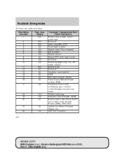
...Location 1 2 3 4 5 6 7 8 9 10 11 12 13 14 15 16 17 Fuse Amp Rating 30A 20A 20A 5A 15A 10A 15A 5A 15A 10A 20A 5A 5A 5A 5A 5A 15A Passenger Compartment Fuse Panel Description Memory seat module..., Driver power seat Moonroof Radio, Amplifier, DVD Front wiper module Flasher relay (Turn, hazards...Heated seats Not used Overdrive cancel switch PATS Rear wiper module, Cluster Power mirror, Manual climate control, TPMS Delayed ...Flexible fuel pump Restraint Control Module (RCM) Memory driver seat switch, Driver seat module, Body Security Module (BSM), PATS LED Instrument...
...Location 1 2 3 4 5 6 7 8 9 10 11 12 13 14 15 16 17 Fuse Amp Rating 30A 20A 20A 5A 15A 10A 15A 5A 15A 10A 20A 5A 5A 5A 5A 5A 15A Passenger Compartment Fuse Panel Description Memory seat module..., Driver power seat Moonroof Radio, Amplifier, DVD Front wiper module Flasher relay (Turn, hazards...Heated seats Not used Overdrive cancel switch PATS Rear wiper module, Cluster Power mirror, Manual climate control, TPMS Delayed ...Flexible fuel pump Restraint Control Module (RCM) Memory driver seat switch, Driver seat module, Body Security Module (BSM), PATS LED Instrument...

Owner's Manual
Page 182
Roadside Emergencies The high-current fuses are coded as follows: Fuse/Relay Location 1 2 3 4 5 6 7 8 9 10 11 12 13 14 15 Fuse Amp Rating 60A** 30A** - 30A** 40A** 60A** 20A** - 20A** 30A** 40A** 50A** 40A** - 15A* Power Distribution Box Description ... #1 BSM Not used Rear defrost Anti-lock Brake System (ABS) pump Delayed accessory, Power windows, Audio Power point #2 Not used Power point #1 ABS module (valves) Powertrain Control Module (PCM) Ignition relay, Starter relay Trailer tow battery charge, Trailer tow turn signals Not used Memory (PCM/DEATC/Cluster), Courtesy lamps 182 REVIEW COPY...
Roadside Emergencies The high-current fuses are coded as follows: Fuse/Relay Location 1 2 3 4 5 6 7 8 9 10 11 12 13 14 15 Fuse Amp Rating 60A** 30A** - 30A** 40A** 60A** 20A** - 20A** 30A** 40A** 50A** 40A** - 15A* Power Distribution Box Description ... #1 BSM Not used Rear defrost Anti-lock Brake System (ABS) pump Delayed accessory, Power windows, Audio Power point #2 Not used Power point #1 ABS module (valves) Powertrain Control Module (PCM) Ignition relay, Starter relay Trailer tow battery charge, Trailer tow turn signals Not used Memory (PCM/DEATC/Cluster), Courtesy lamps 182 REVIEW COPY...

Owner's Manual
Page 183
Roadside Emergencies Fuse/Relay Location 16 17 18 19 20 21 22 23 24 25 26 27 28 29 30 31 32 33 34 35 36 ...Box Description Park lamps, Autolamp parklamps, Front foglamps relay coil Not used PCM with two-speed 4x4 clutch High beam relay Trailer electric brake module Front wiper motor Low beam, Autolamp Ignition switch, PCM diode Not used Brake on-off Fuel pump Trailer tow park lamps, Trailer tow... power Coil on plug (4.6L engine only), Ignition coil (4.0L engine only) Right low beam Left low beam 183 REVIEW COPY: 2004 Explorer (exp), Owners Guide (post-2002-fmt) (own2002), Market: USA English (fus)
Roadside Emergencies Fuse/Relay Location 16 17 18 19 20 21 22 23 24 25 26 27 28 29 30 31 32 33 34 35 36 ...Box Description Park lamps, Autolamp parklamps, Front foglamps relay coil Not used PCM with two-speed 4x4 clutch High beam relay Trailer electric brake module Front wiper motor Low beam, Autolamp Ignition switch, PCM diode Not used Brake on-off Fuel pump Trailer tow park lamps, Trailer tow... power Coil on plug (4.6L engine only), Ignition coil (4.0L engine only) Right low beam Left low beam 183 REVIEW COPY: 2004 Explorer (exp), Owners Guide (post-2002-fmt) (own2002), Market: USA English (fus)
Owner's Manual
Page 260
...undesired operation. Inflate all the tires to the message center. The receiver module then electronically transmits the status to the recommended cold pressure. The tire pressure should be added to the nearest location where air can be checked periodically (at least monthly) using a tire ...tire deflection, amount of control, vehicle rollover and personal injury. 260 REVIEW COPY: 2004 Explorer (exp), Owners Guide (post-2002-fmt) (own2002), Market: USA English (fus) Failure to the receiver module located in this chapter. The tire pressure monitoring system is on all tires appear to ...
...undesired operation. Inflate all the tires to the message center. The receiver module then electronically transmits the status to the recommended cold pressure. The tire pressure should be added to the nearest location where air can be checked periodically (at least monthly) using a tire ...tire deflection, amount of control, vehicle rollover and personal injury. 260 REVIEW COPY: 2004 Explorer (exp), Owners Guide (post-2002-fmt) (own2002), Market: USA English (fus) Failure to the receiver module located in this chapter. The tire pressure monitoring system is on all tires appear to ...

Owner Guide 2nd Printing (Spanish)
Page 374
... variation is now updated. 62 A correct zone setting will eliminate this section. Press the button on the top of the compass module until ZONE appears in normal conditions. Press until ZONE appears in for your vehicle in the instrument cluster display. 5. The display will...2. Driver Controls Usually, when something affects the compass readings, the compass will correct itself after a few days of operating your geographic location by referring to normal operation. Most geographic areas (zones) have a magnetic north compass point that varies slightly from the northerly direction ...
... variation is now updated. 62 A correct zone setting will eliminate this section. Press the button on the top of the compass module until ZONE appears in normal conditions. Press until ZONE appears in for your vehicle in the instrument cluster display. 5. The display will...2. Driver Controls Usually, when something affects the compass readings, the compass will correct itself after a few days of operating your geographic location by referring to normal operation. Most geographic areas (zones) have a magnetic north compass point that varies slightly from the northerly direction ...

Owner Guide 2nd Printing (Spanish)
Page 375
... sure all vehicle doors are shut. 1. Driver Controls Compass calibration adjustment Perform this adjustment in the ON position, the message center, located on your instrument cluster, displays important vehicle information through a constant monitor of vehicle systems. You may select display features on the top... of the compass module until ZONE appears in circles until ZONE disappears and CAL is now calibrated. MESSAGE CENTER (IF EQUIPPED) With the ignition in...
... sure all vehicle doors are shut. 1. Driver Controls Compass calibration adjustment Perform this adjustment in the ON position, the message center, located on your instrument cluster, displays important vehicle information through a constant monitor of vehicle systems. You may select display features on the top... of the compass module until ZONE appears in circles until ZONE disappears and CAL is now calibrated. MESSAGE CENTER (IF EQUIPPED) With the ignition in...
Owner Guide 2nd Printing (Spanish)
Page 397
... ignition switch is turned to the OFF position. Enter the factory set 5-digit entry code; this code is located on the owner's wallet card in the glove box, is marked on the computer module, and is pressed, or • after the ignition has been turned to the ON position, or • the...
... ignition switch is turned to the OFF position. Enter the factory set 5-digit entry code; this code is located on the owner's wallet card in the glove box, is marked on the computer module, and is pressed, or • after the ignition has been turned to the ON position, or • the...

Owner Guide 2nd Printing (Spanish)
Page 414
... to help further reduce the risk of the safety restraints, refer to Safety Restraints in this chapter. Pull the seat release lever located on the proper operation of air bag-related injuries. The seatback will latch into the upright position. 3. A collection of occupants ...energy management retractors, and safety belt usage sensors. • Driver's seat position sensor. • Front crash severity sensor. • Restraints Control Module (RCM). • Restraint system warning light and back-up tone. • The electrical wiring for the air bags, crash sensor(s), safety belt...
... to help further reduce the risk of the safety restraints, refer to Safety Restraints in this chapter. Pull the seat release lever located on the proper operation of air bag-related injuries. The seatback will latch into the upright position. 3. A collection of occupants ...energy management retractors, and safety belt usage sensors. • Driver's seat position sensor. • Front crash severity sensor. • Restraints Control Module (RCM). • Restraint system warning light and back-up tone. • The electrical wiring for the air bags, crash sensor(s), safety belt...

Owner Guide 2nd Printing (Spanish)
Page 433
...front airbags. • Two side crash sensors mounted at the base of the B-pillar (one on each side). • Two side crash sensors located at the c-pillar behind the rear doors (one on each side of a rollover event is designed to activate when the vehicle sustains lateral deceleration sufficient... with a gas generator concealed behind the headliner and above the doors (one on each side). • Roll over sensor in the restraints control module (RCM). The Safety Canopy will flex to the deployment of injuries related to open above the doors along the side window openings. The...
...front airbags. • Two side crash sensors mounted at the base of the B-pillar (one on each side). • Two side crash sensors located at the c-pillar behind the rear doors (one on each side of a rollover event is designed to activate when the vehicle sustains lateral deceleration sufficient... with a gas generator concealed behind the headliner and above the doors (one on each side). • Roll over sensor in the restraints control module (RCM). The Safety Canopy will flex to the deployment of injuries related to open above the doors along the side window openings. The...

Owner Guide 2nd Printing (Spanish)
Page 489
... fuses are coded as follows: Fuse/Relay Location 1 2 3 4 5 6 7 8 9 10 11 12 13 14 15 16 17 Fuse Amp Rating 30A 20A 20A 5A 15A 10A 15A 5A 15A 10A 20A 5A 5A 5A 5A 5A 15A Passenger Compartment Fuse Panel Description Memory seat module, Driver power seat Moonroof Radio, Amplifier,...mirrors Heated PCV (4.0L engine only) Not used Heated backlight relay coil, A/C clutch contact Heated seats Not used Overdrive cancel switch PATS Rear wiper module, Cluster Power mirror, Manual climate control, TPMS Delayed accessory relay coil/Battery saver coil and contact/Reading and glove box lamps Flexible fuel pump ...
... fuses are coded as follows: Fuse/Relay Location 1 2 3 4 5 6 7 8 9 10 11 12 13 14 15 16 17 Fuse Amp Rating 30A 20A 20A 5A 15A 10A 15A 5A 15A 10A 20A 5A 5A 5A 5A 5A 15A Passenger Compartment Fuse Panel Description Memory seat module, Driver power seat Moonroof Radio, Amplifier,...mirrors Heated PCV (4.0L engine only) Not used Heated backlight relay coil, A/C clutch contact Heated seats Not used Overdrive cancel switch PATS Rear wiper module, Cluster Power mirror, Manual climate control, TPMS Delayed accessory relay coil/Battery saver coil and contact/Reading and glove box lamps Flexible fuel pump ...

Owner Guide 2nd Printing (Spanish)
Page 493
Roadside Emergencies The high-current fuses are coded as follows: Fuse/Relay Location 1 2 3 4 5 6 7 8 9 10 11 12 13 14 15 Fuse Amp Rating 60A** 30A** - 30A** 40A** 60A** 20A** - 20A** 30A** 40A** 50A** 40A** - 15A* Power Distribution Box Description PJB #1 BSM Not used Rear defrost Anti-lock Brake System (ABS) pump Delayed accessory, Power windows, Audio Power point #2 Not used Power point #1 ABS module (valves) Powertrain Control Module (PCM) Ignition relay, Starter relay Trailer tow battery charge, Trailer tow turn signals Not used Memory (PCM/DEATC/Cluster), Courtesy lamps 181
Roadside Emergencies The high-current fuses are coded as follows: Fuse/Relay Location 1 2 3 4 5 6 7 8 9 10 11 12 13 14 15 Fuse Amp Rating 60A** 30A** - 30A** 40A** 60A** 20A** - 20A** 30A** 40A** 50A** 40A** - 15A* Power Distribution Box Description PJB #1 BSM Not used Rear defrost Anti-lock Brake System (ABS) pump Delayed accessory, Power windows, Audio Power point #2 Not used Power point #1 ABS module (valves) Powertrain Control Module (PCM) Ignition relay, Starter relay Trailer tow battery charge, Trailer tow turn signals Not used Memory (PCM/DEATC/Cluster), Courtesy lamps 181

Owner Guide 2nd Printing (Spanish)
Page 494
Roadside Emergencies Fuse/Relay Location 16 17 18 19 20 21 22 23 24 25 26 27 28 29 30 31 32 33 34 35 36 37 38 39 40 ... Distribution Box Description Park lamps, Autolamp parklamps, Front foglamps relay coil Not used PCM with two-speed 4x4 clutch High beam relay Trailer electric brake module Front wiper motor Low beam, Autolamp Ignition switch Not used Brake on-off Fuel pump Trailer tow park lamps, Trailer tow back-up Horn relay...
Roadside Emergencies Fuse/Relay Location 16 17 18 19 20 21 22 23 24 25 26 27 28 29 30 31 32 33 34 35 36 37 38 39 40 ... Distribution Box Description Park lamps, Autolamp parklamps, Front foglamps relay coil Not used PCM with two-speed 4x4 clutch High beam relay Trailer electric brake module Front wiper motor Low beam, Autolamp Ignition switch Not used Brake on-off Fuel pump Trailer tow park lamps, Trailer tow back-up Horn relay...

Owner Guide 2nd Printing (Spanish)
Page 572
... factors, one or more tire warning information, refer to verify that may increase approximately 14 to 28 kPa (2 to the receiver module located in each pneumatic tire. The tire pressure monitoring system is dependent upon several factors such as being the contained air temperature (temperature ... the message center. This increase in ambient temperature. Inflate all tires appear to be inflated, carefully drive the vehicle to the nearest location where air can be detected by the TPMS as rate of tire rotation, tire deflection, amount of braking, etc. In similar manner...
... factors, one or more tire warning information, refer to verify that may increase approximately 14 to 28 kPa (2 to the receiver module located in each pneumatic tire. The tire pressure monitoring system is dependent upon several factors such as being the contained air temperature (temperature ... the message center. This increase in ambient temperature. Inflate all tires appear to be inflated, carefully drive the vehicle to the nearest location where air can be detected by the TPMS as rate of tire rotation, tire deflection, amount of braking, etc. In similar manner...


