
Owners Manual
Page 5
... Kawasaki motorcycle. The Service Manual contains detailed disassembly and maintenance information. Foreword Congratulations on their own work should, of course, be thoroughly familiar with the proper operation of your motorcycle at all times so that you can refer to attain awareness of Kawasaki's advanced engineering, exhaustive testing, and continuous striving for superior reliability, safety and performance. Keep this Owner's Manual aboard your motorcycle's controls, its...
... Kawasaki motorcycle. The Service Manual contains detailed disassembly and maintenance information. Foreword Congratulations on their own work should, of course, be thoroughly familiar with the proper operation of your motorcycle at all times so that you can refer to attain awareness of Kawasaki's advanced engineering, exhaustive testing, and continuous striving for superior reliability, safety and performance. Keep this Owner's Manual aboard your motorcycle's controls, its...
Owners Manual
Page 11
... for High Speed Operation ...13 13 13 13 14 15 15 16 16 17 17 18 18 19 19 20 22 GENERAL INFORMATION ...Specifications ...Serial Number Locations...Location of Labels ...Location of Parts ...Meter Instruments ...Indicators ...Speedometer/Tachometer ...Display Setting...Clock...Features ...Keys ...Ignition Switch/Steering Lock ...Right Handlebar Switches...Left Handlebar Switches ...Brake Lever Adjuster...Clutch Lever Adjuster...Fuel ...Fuel Requirements ...Filling the Tank...24...
... for High Speed Operation ...13 13 13 13 14 15 15 16 16 17 17 18 18 19 19 20 22 GENERAL INFORMATION ...Specifications ...Serial Number Locations...Location of Labels ...Location of Parts ...Meter Instruments ...Indicators ...Speedometer/Tachometer ...Display Setting...Clock...Features ...Keys ...Ignition Switch/Steering Lock ...Right Handlebar Switches...Left Handlebar Switches ...Brake Lever Adjuster...Clutch Lever Adjuster...Fuel ...Fuel Requirements ...Filling the Tank...24...
Owners Manual
Page 12
Break-In ...Starting the Engine ...Jump Starting ...Moving Off...Shifting Gears ...Braking ...Anti-lock Brake System (ABS) ...Stopping the Engine...Stopping the Motorcycle in an Emergency ...Parking ...MAINTENANCE AND ADJUSTMENT Daily Checks ...Periodic Maintenance...Engine Oil ...Coolant... 66 67 70 70 71 72 75 75 76 79 81 82 84 85 87 88 89 91 93 96 101 105 Air Cleaner ...Throttle Control System ...Idle Speed ...Clutch ...Drive Chain ...Brakes ...Brake Light Switches...Suspension System ...Rear Shock Absorber ...Setting Tables ...Wheels ...Battery...Headlight ...Fuses ...General Lubrication...
Break-In ...Starting the Engine ...Jump Starting ...Moving Off...Shifting Gears ...Braking ...Anti-lock Brake System (ABS) ...Stopping the Engine...Stopping the Motorcycle in an Emergency ...Parking ...MAINTENANCE AND ADJUSTMENT Daily Checks ...Periodic Maintenance...Engine Oil ...Coolant... 66 67 70 70 71 72 75 75 76 79 81 82 84 85 87 88 89 91 93 96 101 105 Air Cleaner ...Throttle Control System ...Idle Speed ...Clutch ...Drive Chain ...Brakes ...Brake Light Switches...Suspension System ...Rear Shock Absorber ...Setting Tables ...Wheels ...Battery...Headlight ...Fuses ...General Lubrication...

Owners Manual
Page 17
... is in an unsafe riding condition. Make sure that impairs the performance of the steering assembly and can result in weight distribution and aerodynamic forces. Weight attached to the handlebars or front...rack. Other Load 1. Recheck baggage security as often as possible (not while the motorcycle is in operation. Accessories 1. Do not install accessories or carry baggage that you are riding. Fairings, windshields, backrests, and other large items have not adversely affected any lighting components, road clearance, banking capability (i.e., lean angle), control operation, wheel...
... is in an unsafe riding condition. Make sure that impairs the performance of the steering assembly and can result in weight distribution and aerodynamic forces. Weight attached to the handlebars or front...rack. Other Load 1. Recheck baggage security as often as possible (not while the motorcycle is in operation. Accessories 1. Do not install accessories or carry baggage that you are riding. Fairings, windshields, backrests, and other large items have not adversely affected any lighting components, road clearance, banking capability (i.e., lean angle), control operation, wheel...

Owners Manual
Page 21
... Select Correct Gear Speeds Look Over Your Shoulder Use Both Front and Rear Brakes you may misjudge a vehicle's distance and speed, or you remove even one brake for sudden braking may cause loss of control, especially when riding in wet conditions or on loose road surfaces, when the ability to make sure the way is power to control the motorcycle. 20 SAFETY INFORMATION Wear...
... Select Correct Gear Speeds Look Over Your Shoulder Use Both Front and Rear Brakes you may misjudge a vehicle's distance and speed, or you remove even one brake for sudden braking may cause loss of control, especially when riding in wet conditions or on loose road surfaces, when the ability to make sure the way is power to control the motorcycle. 20 SAFETY INFORMATION Wear...

Owners Manual
Page 22
... the necessary power. Lubricate the drive chain after wet -weather riding to normal operating performance. To avoid engine damage and rear wheel lock-up do not downshift at a slow speed and apply the brakes several times to help control vehicle speed by closing the throttle so that the engine can act as an auxiliary brake. Braking performance is necessary to pass another vehicle, shift to a lower gear to avoid skidding the rear wheel from too...
... the necessary power. Lubricate the drive chain after wet -weather riding to normal operating performance. To avoid engine damage and rear wheel lock-up do not downshift at a slow speed and apply the brakes several times to help control vehicle speed by closing the throttle so that the engine can act as an auxiliary brake. Braking performance is necessary to pass another vehicle, shift to a lower gear to avoid skidding the rear wheel from too...
Owners Manual
Page 24
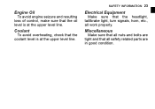
Make sure that all work properly. Engine Oil Make sure that all safety related parts are tight and that the headlight, tail/brake light, turn signals, horn, etc., all nuts and bolts are in good condition. Electrical Equipment Coolant Miscellaneous SAFETY INFORMATION 23 To avoid engine seizure and resulting loss of control, make sure that the coolant level is at the upper level line. To avoid overheating, check that the oil level is at the upper level line.
Make sure that all work properly. Engine Oil Make sure that all safety related parts are tight and that the headlight, tail/brake light, turn signals, horn, etc., all nuts and bolts are in good condition. Electrical Equipment Coolant Miscellaneous SAFETY INFORMATION 23 To avoid engine seizure and resulting loss of control, make sure that the coolant level is at the upper level line. To avoid overheating, check that the oil level is at the upper level line.

Owners Manual
Page 40
GENERAL INFORMATION 39 1. 2. 3. 4. 5. 6. 7. Rear Brake Pedal Rear Brake Light Switch Idle Adjusting Screw Oil Level Inspection Window Muffler Spring Preload Adjuster Rear Shock Absorber Tail/Brake Light Battery Fuse Boxes Fuel Tank Cap Brake Fluid Reservoir (Rear) Brake Discs Brake Calipers 8. 9. 10. 11. 12. 13. 14.
GENERAL INFORMATION 39 1. 2. 3. 4. 5. 6. 7. Rear Brake Pedal Rear Brake Light Switch Idle Adjusting Screw Oil Level Inspection Window Muffler Spring Preload Adjuster Rear Shock Absorber Tail/Brake Light Battery Fuse Boxes Fuel Tank Cap Brake Fluid Reservoir (Rear) Brake Discs Brake Calipers 8. 9. 10. 11. 12. 13. 14.

Owners Manual
Page 41
Right Meter Button 4. Speedometer 8. Economical Riding Indicator When the ignition switch is turned on, all LCD functions are shown for a few seconds, then the multifunction meter turns to operational mode. Multifunction Display - Current Mileage/Average Mileage/Cruising Range 7. Left Meter Button 3. Fuel Gauge 9. Clock 6. 40 GENERAL INFORMATION Meter Instruments 1. Trip Meter A/B - Tachometer 2. Multifunction Meter 5. Odometer -
Right Meter Button 4. Speedometer 8. Economical Riding Indicator When the ignition switch is turned on, all LCD functions are shown for a few seconds, then the multifunction meter turns to operational mode. Multifunction Display - Current Mileage/Average Mileage/Cruising Range 7. Left Meter Button 3. Fuel Gauge 9. Clock 6. 40 GENERAL INFORMATION Meter Instruments 1. Trip Meter A/B - Tachometer 2. Multifunction Meter 5. Odometer -

Owners Manual
Page 66
D. GENERAL INFORMATION 65 the key hole cover. • Lift Insert the ignition key into • Push place with the key inserted. C. A. Key Hole Cover B. Fuel Tank Cap ○Do NOTE not exceed the maximum fuel level as shown. the key clockwise while pushing • Turn down into the fuel • tank cap. B. Ignition Key C. Tank Cap Fuel Tank Top Level Bottom of Filler Neck (Maximum Fuel Level) A. the fuel tank cap. • Open Add fuel. • the fuel tank cap down the fuel tank cap.
D. GENERAL INFORMATION 65 the key hole cover. • Lift Insert the ignition key into • Push place with the key inserted. C. A. Key Hole Cover B. Fuel Tank Cap ○Do NOTE not exceed the maximum fuel level as shown. the key clockwise while pushing • Turn down into the fuel • tank cap. B. Ignition Key C. Tank Cap Fuel Tank Top Level Bottom of Filler Neck (Maximum Fuel Level) A. the fuel tank cap. • Open Add fuel. • the fuel tank cap down the fuel tank cap.

Owners Manual
Page 72
... then erased when the ignition is switched off. ○At no time other vehicle manufacturers, Kawasaki has equipped this device is EDR data stored for retrieval. ○This device does not collect or store personal data or information (e.g. Rear View Mirror B. NOTE GENERAL INFORMATION 71 boot up, and loosen the upper hexagonal area and turn the stay by...
... then erased when the ignition is switched off. ○At no time other vehicle manufacturers, Kawasaki has equipped this device is EDR data stored for retrieval. ○This device does not collect or store personal data or information (e.g. Rear View Mirror B. NOTE GENERAL INFORMATION 71 boot up, and loosen the upper hexagonal area and turn the stay by...

Owners Manual
Page 84
... transmission cannot be done below the vehicle speeds for each gear shown in the table. When the motorcycle is equipped with a NOTE Shifting up on the shift pedal while standing still. HOW TO RIDE THE MOTORCYCLE 83 WARNING Downshifting to a lower gear at high speed causes engine rpm to increase excessively, potentially damaging the engine and it may also cause the rear wheel to...
... transmission cannot be done below the vehicle speeds for each gear shown in the table. When the motorcycle is equipped with a NOTE Shifting up on the shift pedal while standing still. HOW TO RIDE THE MOTORCYCLE 83 WARNING Downshifting to a lower gear at high speed causes engine rpm to increase excessively, potentially damaging the engine and it may also cause the rear wheel to...

Owners Manual
Page 100
MAINTENANCE AND ADJUSTMENT 99 year (*A) Items Drive chain slack (*C) Drive chain wear (*C) Drive chain guide wear Brake system Brake operation (effectiveness, play, no drag) Brake fluid level Brake fluid (front and rear) Brake hoses Rubber parts of brake master cylinder and caliper :1 :1 :0.5 :2 :4 :4 Odometer Reading (*B) × 1 000 km (× 1 000 mile) See 1 6 12 18 24 Page (0.6) (3.8) (7.6) (11.4) (15.2) : every 1 000 km (600 mile) 116 - - - - 121 - - : every 48 000 km (30 000 mile) -
MAINTENANCE AND ADJUSTMENT 99 year (*A) Items Drive chain slack (*C) Drive chain wear (*C) Drive chain guide wear Brake system Brake operation (effectiveness, play, no drag) Brake fluid level Brake fluid (front and rear) Brake hoses Rubber parts of brake master cylinder and caliper :1 :1 :0.5 :2 :4 :4 Odometer Reading (*B) × 1 000 km (× 1 000 mile) See 1 6 12 18 24 Page (0.6) (3.8) (7.6) (11.4) (15.2) : every 1 000 km (600 mile) 116 - - - - 121 - - : every 48 000 km (30 000 mile) -

Owners Manual
Page 101
100 MAINTENANCE AND ADJUSTMENT year (*A) Items Brake pad wear (*C) Brake light switch operation Suspension system Steering play Steering stem bearings Electrical system :1 :1 :2 :1 Odometer Reading (*B) × 1 000 km (× 1 000 mile) See 1 6 12 18 24 Page (0.6) (3.8) (7.6) (11.4) (15.2) 122 123 - - - - - :1 - - ○ Spark plugs Chassis parts Condition of bolts, nuts and fasteners
100 MAINTENANCE AND ADJUSTMENT year (*A) Items Brake pad wear (*C) Brake light switch operation Suspension system Steering play Steering stem bearings Electrical system :1 :1 :2 :1 Odometer Reading (*B) × 1 000 km (× 1 000 mile) See 1 6 12 18 24 Page (0.6) (3.8) (7.6) (11.4) (15.2) 122 123 - - - - - :1 - - ○ Spark plugs Chassis parts Condition of bolts, nuts and fasteners
Owners Manual
Page 103
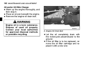
... local authorities for approved disposal methods or possible recycling. If the oil filter is a toxic substance. Dispose of used oil properly. an oil pan beneath the engine. • Place Remove the engine oil drain bolt. • WARNING Engine oil is to the • ground. A. 102 MAINTENANCE AND ADJUSTMENT Oil and/or Oil Filter Change up the engine thoroughly, and • Warm then stop it with • Let the...
... local authorities for approved disposal methods or possible recycling. If the oil filter is a toxic substance. Dispose of used oil properly. an oil pan beneath the engine. • Place Remove the engine oil drain bolt. • WARNING Engine oil is to the • ground. A. 102 MAINTENANCE AND ADJUSTMENT Oil and/or Oil Filter Change up the engine thoroughly, and • Warm then stop it with • Let the...

Owners Manual
Page 124
... of the rear brake • Check light switch by depressing the brake pedal. Lining Thickness C. 1 mm (0.04 in .) the light does not come on, adjust • If the rear brake light switch. A. The brake light should go on when • The the front brake is applied. Brake Pedal B. 10 mm (0.39 in .) Brake Light Switches Brake Light Switch Inspection the ignition switch on. • Turn brake light should go on after the proper pedal travel. brake light switch. Rear Brake Pads B.
... of the rear brake • Check light switch by depressing the brake pedal. Lining Thickness C. 1 mm (0.04 in .) the light does not come on, adjust • If the rear brake light switch. A. The brake light should go on when • The the front brake is applied. Brake Pedal B. 10 mm (0.39 in .) Brake Light Switches Brake Light Switch Inspection the ignition switch on. • Turn brake light should go on after the proper pedal travel. brake light switch. Rear Brake Pads B.

Owners Manual
Page 125
... Rear Shock Absorber Spring Preload Adjustment The spring preload adjuster on the rear shock absorber has 7 positions. B. C. 124 MAINTENANCE AND ADJUSTMENT Brake Pedal Travel NOTICE To avoid damaging the electrical connections inside the switch, be sure that the switch body does not turn during adjustment. 10 mm (0.39 in.) Brake Light Switch Adjustment adjust the rear brake light switch, • To move the switch up or down by turning the adjusting nut. Rear Brake Light Switch...
... Rear Shock Absorber Spring Preload Adjustment The spring preload adjuster on the rear shock absorber has 7 positions. B. C. 124 MAINTENANCE AND ADJUSTMENT Brake Pedal Travel NOTICE To avoid damaging the electrical connections inside the switch, be sure that the switch body does not turn during adjustment. 10 mm (0.39 in.) Brake Light Switch Adjustment adjust the rear brake light switch, • To move the switch up or down by turning the adjusting nut. Rear Brake Light Switch...

Owners Manual
Page 146
... water in delicate areas such as in conditions that allow debris or flammable material to inspecting for build-up of debris or flammable material in and around the vehicle, inspect the engine, electrical component and exhaust areas frequently. Allow the engine to seals, • Avoid brake pads, and tires. applying degreaser to cool, then remove any collected debris. MAINTENANCE AND ADJUSTMENT 145 WARNING...
... water in delicate areas such as in conditions that allow debris or flammable material to inspecting for build-up of debris or flammable material in and around the vehicle, inspect the engine, electrical component and exhaust areas frequently. Allow the engine to seals, • Avoid brake pads, and tires. applying degreaser to cool, then remove any collected debris. MAINTENANCE AND ADJUSTMENT 145 WARNING...
Owners Manual
Page 156
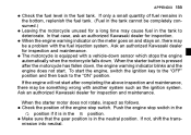
... Kawasaki dealer for a long time may cause fuel in the position. Ask an authorized Kawasaki dealer sumed.) • for inspection and maintenance. • • When the starter motor does not rotate, inspect as the ignition system. When the starter button is equipped with a vehicle-down sensor which stops the engine automatically when the motorcycle falls down , the engine warning indicator blinks and the engine does not start...
... Kawasaki dealer for a long time may cause fuel in the position. Ask an authorized Kawasaki dealer sumed.) • for inspection and maintenance. • • When the starter motor does not rotate, inspect as the ignition system. When the starter button is equipped with a vehicle-down sensor which stops the engine automatically when the motorcycle falls down , the engine warning indicator blinks and the engine does not start...
Owners Manual
Page 157
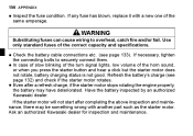
... not start after a refresh charge, if the starter motor stops rotating the engine properly, the battery may be something wrong with a new one of the • Inspect same amperage. Even after completing the above inspection and maintenance, there may have deteriorated. case of slow blinking of the turn signal lights, low volume of the correct capacity and specifications. WARNING Substituting fuses can cause wiring...
... not start after a refresh charge, if the starter motor stops rotating the engine properly, the battery may be something wrong with a new one of the • Inspect same amperage. Even after completing the above inspection and maintenance, there may have deteriorated. case of slow blinking of the turn signal lights, low volume of the correct capacity and specifications. WARNING Substituting fuses can cause wiring...
