

Owners Manual
Page 8
... ...Warning/Indicator Lights ...Service Code ...Keys ...Ignition Switch/Steering Lock ...Audio System ...Important Notice ...Operating Precautions ...Getting Started ...Radio Power On/Off...Radio (FM/AM/WX BAND)...9 13 14 17 20 20 21 22 23 29 31 34 35 36 39 39 39 43 44 44 PTT (Push to Talk) ...Left Handlebar Switches ...Dimmer Switch ...Turn Signal Switch...Horn Button ...Audio Control Switches ...Right Handlebar Switches...Hazard Switch ...Engine Stop Switch ...Starter Button ...Meter Unit Switch ...Electronic Cruise Control ON...
... ...Warning/Indicator Lights ...Service Code ...Keys ...Ignition Switch/Steering Lock ...Audio System ...Important Notice ...Operating Precautions ...Getting Started ...Radio Power On/Off...Radio (FM/AM/WX BAND)...9 13 14 17 20 20 21 22 23 29 31 34 35 36 39 39 39 43 44 44 PTT (Push to Talk) ...Left Handlebar Switches ...Dimmer Switch ...Turn Signal Switch...Horn Button ...Audio Control Switches ...Right Handlebar Switches...Hazard Switch ...Engine Stop Switch ...Starter Button ...Meter Unit Switch ...Electronic Cruise Control ON...
Owners Manual
Page 9
Starting the Engine ...Jump Starting ...Moving Off...Shifting Gears ...Braking ...Kawasaki Advanced Coactive-braking Technology (K-ACT) - Electronic Cruise Control Switch (SET/- Anti-lock Brake System (ABS) for models equipped with K-ACT ABS...K-ACT ABS Indicator Light ...Stopping the Engine...Stopping the Motorcycle in an Emergency ...Parking ...Catalytic Converter...Electronic Throttle Valve (ETV) System...SAFE OPERATION ...Safe Riding Technique ... 96 102 104 104 107 110 111 113 114 117 118 119 120 121 123 124...
Starting the Engine ...Jump Starting ...Moving Off...Shifting Gears ...Braking ...Kawasaki Advanced Coactive-braking Technology (K-ACT) - Electronic Cruise Control Switch (SET/- Anti-lock Brake System (ABS) for models equipped with K-ACT ABS...K-ACT ABS Indicator Light ...Stopping the Engine...Stopping the Motorcycle in an Emergency ...Parking ...Catalytic Converter...Electronic Throttle Valve (ETV) System...SAFE OPERATION ...Safe Riding Technique ... 96 102 104 104 107 110 111 113 114 117 118 119 120 121 123 124...

Owners Manual
Page 10
... Periodic Maintenance Chart...Engine Oil ...Cooling System ...Drive Belt...Spark Plugs...Evaporative Emission Control System (California model only) ...Valve Clearance ...Kawasaki Clean Air System ...Air Cleaner ...Throttle Control System ...Idle Speed ...Clutch ...Brakes ... 127 130 132 136 149 156 162 163 164 165 165 166 169 170 174 175 Brake Light Switches...Rear Shock Absorbers ...Wheels ...Battery...Headlight Beam...Fuses ...General Lubrication...Cleaning Your Motorcycle ...Bolt and Nut Tightening...STORAGE ...TROUBLESHOOTING GUIDE...YOUR WARRANTY/OWNER SATISFACTION ...REPORTING SAFETY...
... Periodic Maintenance Chart...Engine Oil ...Cooling System ...Drive Belt...Spark Plugs...Evaporative Emission Control System (California model only) ...Valve Clearance ...Kawasaki Clean Air System ...Air Cleaner ...Throttle Control System ...Idle Speed ...Clutch ...Brakes ... 127 130 132 136 149 156 162 163 164 165 165 166 169 170 174 175 Brake Light Switches...Rear Shock Absorbers ...Wheels ...Battery...Headlight Beam...Fuses ...General Lubrication...Cleaning Your Motorcycle ...Bolt and Nut Tightening...STORAGE ...TROUBLESHOOTING GUIDE...YOUR WARRANTY/OWNER SATISFACTION ...REPORTING SAFETY...

Owners Manual
Page 21
... condition. 9. Maximum Load Weight of the motorcycle. Do not install accessories or carry baggage that impairs the performance of rider, passenger, baggage, and accessories must not exceed 180 kg (397 lb). Fairings, windshields, backrests, and other large items have not adversely affected any lighting components, road clearance, banking capability (i.e., lean angle), control operation, wheel travel, front fork movement, or any other vehicle...
... condition. 9. Maximum Load Weight of the motorcycle. Do not install accessories or carry baggage that impairs the performance of rider, passenger, baggage, and accessories must not exceed 180 kg (397 lb). Fairings, windshields, backrests, and other large items have not adversely affected any lighting components, road clearance, banking capability (i.e., lean angle), control operation, wheel travel, front fork movement, or any other vehicle...

Owners Manual
Page 34
... system. 32 GENERAL INFORMATION : When the transmission is in neutral position, the neutral indicator light goes on. : When the turn signal switch push is pushed to the right, the right turn signal indicator light starts flashing. : When the headlight is on high beam, the high beam indicator light goes on. (For models equipped with the K-ACT ABS, the indicator goes on and remains...
... system. 32 GENERAL INFORMATION : When the transmission is in neutral position, the neutral indicator light goes on. : When the turn signal switch push is pushed to the right, the right turn signal indicator light starts flashing. : When the headlight is on high beam, the high beam indicator light goes on. (For models equipped with the K-ACT ABS, the indicator goes on and remains...
Owners Manual
Page 39
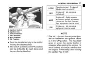
... ignition key. All electrical equipment can be used . Ignition Switch B. LOCK position and OFF position • The can be shifted to, by push down and turn on whenever the ignition switch is released after turning the ignition key to the left for • Turn locking the steering lock. Engine off . Engine on when the starter button is in the ON position. Ignition Key C. OFF Position E. The headlight goes on . ACC Position F. Audio system, accessory socket, accessory connector, fog light...
... ignition key. All electrical equipment can be used . Ignition Switch B. LOCK position and OFF position • The can be shifted to, by push down and turn on whenever the ignition switch is released after turning the ignition key to the left for • Turn locking the steering lock. Engine off . Engine on when the starter button is in the ON position. Ignition Key C. OFF Position E. The headlight goes on . ACC Position F. Audio system, accessory socket, accessory connector, fog light...

Owners Manual
Page 86
Hold Portions Rider's Seat Removal Remove the passenger's seat. Pull up the rear of the rider's seat to clear the hold portions, and then pull the seat to the rear. • • Rider's Seat Installation To install the rider's seat, insert the tab at the holder and engage the two grommet holes onto the two projections. • 84 GENERAL INFORMATION A. Front A. Rider's Seat B. Passenger's Seat B.
Hold Portions Rider's Seat Removal Remove the passenger's seat. Pull up the rear of the rider's seat to clear the hold portions, and then pull the seat to the rear. • • Rider's Seat Installation To install the rider's seat, insert the tab at the holder and engage the two grommet holes onto the two projections. • 84 GENERAL INFORMATION A. Front A. Rider's Seat B. Passenger's Seat B.

Owners Manual
Page 87
A. D. Tab Holder Holes Projections Passenger's Seat Installation Insert the tab on the rear of the passenger's seat into the left and right projections at the front of the passenger's seat into the slot on the frame. • • A. B. C. Insert the left and right holes on the rear fender. Tab Holder Projections Holes up the front and rear ends of the pas• Push senger's seat until the lock clicks. C. GENERAL INFORMATION 85 down the front part of • Pull the passenger's and rider's seats to make sure they are securely locked. D. B.
A. D. Tab Holder Holes Projections Passenger's Seat Installation Insert the tab on the rear of the passenger's seat into the left and right projections at the front of the passenger's seat into the slot on the frame. • • A. B. C. Insert the left and right holes on the rear fender. Tab Holder Projections Holes up the front and rear ends of the pas• Push senger's seat until the lock clicks. C. GENERAL INFORMATION 85 down the front part of • Pull the passenger's and rider's seats to make sure they are securely locked. D. B.
Owners Manual
Page 113
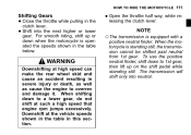
... is equipped with a WARNING Downshifting at high speed can make the rear wheel skid and cause an accident resulting in the table below. The transmission will shift only into the next higher or lower gear. For smooth riding, shift up on the shift pedal while standing still. the throttle half way, while re• Open leasing the clutch lever. When shifting down when the...
... is equipped with a WARNING Downshifting at high speed can make the rear wheel skid and cause an accident resulting in the table below. The transmission will shift only into the next higher or lower gear. For smooth riding, shift up on the shift pedal while standing still. the throttle half way, while re• Open leasing the clutch lever. When shifting down when the...

Owners Manual
Page 119
... rear brakes work normally as a conventional brake system. However, the effectiveness of the brake, especially the rear brake, decreases compared to "Battery maintenance" section. The light does not go on . HOW TO RIDE THE MOTORCYCLE 117 at the speed of approx. 5 You should have taken place in reference to when K-ACT system functions normally. Keep the battery in good condition in the K-ACT ABS...
... rear brakes work normally as a conventional brake system. However, the effectiveness of the brake, especially the rear brake, decreases compared to "Battery maintenance" section. The light does not go on . HOW TO RIDE THE MOTORCYCLE 117 at the speed of approx. 5 You should have taken place in reference to when K-ACT system functions normally. Keep the battery in good condition in the K-ACT ABS...

Owners Manual
Page 130
... a 280 kPa (2.80 kgf/cm², 40 psi) 397 lb) Load Rear Install the air valve cap. Brakes ...Brake pad wear: Lining thickness more than 1 mm (0.04 in .). Check that steering and suspension components, axles, and all controls are properly tightened or fastened. Engine stop switch ...Stops engine. Electrical equipment ...All lights and horn work. Nuts, bolts, fasteners .. Coolant ...No coolant leakage. Side stand ...Returns to its fully up position by...
... a 280 kPa (2.80 kgf/cm², 40 psi) 397 lb) Load Rear Install the air valve cap. Brakes ...Brake pad wear: Lining thickness more than 1 mm (0.04 in .). Check that steering and suspension components, axles, and all controls are properly tightened or fastened. Engine stop switch ...Stops engine. Electrical equipment ...All lights and horn work. Nuts, bolts, fasteners .. Coolant ...No coolant leakage. Side stand ...Returns to its fully up position by...

Owners Manual
Page 142
inspect Every 1 6 12 18 24 30 36 (0.6) (3.75) (7.5) (11.25) (15) (18.75) (22.5) Clutch and drive train: • 6 months year year 174 • • • 174 - - Periodic Inspection (Chassis Related Items) Frequency Whichever comes first *Odometer Reading km × 1000 (mile × 1000) See Page Operation (Chassis Items) Clutch operation (play, engagement, disengagement) - 140 MAINTENANCE AND ADJUSTMENT 2. inspect Clutch fluid leak inspect Clutch hose damage - inspect Clutch fluid level -
inspect Every 1 6 12 18 24 30 36 (0.6) (3.75) (7.5) (11.25) (15) (18.75) (22.5) Clutch and drive train: • 6 months year year 174 • • • 174 - - Periodic Inspection (Chassis Related Items) Frequency Whichever comes first *Odometer Reading km × 1000 (mile × 1000) See Page Operation (Chassis Items) Clutch operation (play, engagement, disengagement) - 140 MAINTENANCE AND ADJUSTMENT 2. inspect Clutch fluid leak inspect Clutch hose damage - inspect Clutch fluid level -

Owners Manual
Page 145
MAINTENANCE AND ADJUSTMENT 143 Frequency Whichever comes first *Odometer Reading km × 1000 (mile × 1000) See Page Operation (Chassis Items) Brake hose installation condition inspect Every 1 6 12 18 24 30 36 (0.6) (3.75) (7.5) (11.25) (15) (18.75) (22.5) year 176 Brake fluid level 6 months inspect Brake operation (effectiveness, play, drag) inspect Brake light switch operation inspect year 176 179 180
MAINTENANCE AND ADJUSTMENT 143 Frequency Whichever comes first *Odometer Reading km × 1000 (mile × 1000) See Page Operation (Chassis Items) Brake hose installation condition inspect Every 1 6 12 18 24 30 36 (0.6) (3.75) (7.5) (11.25) (15) (18.75) (22.5) year 176 Brake fluid level 6 months inspect Brake operation (effectiveness, play, drag) inspect Brake light switch operation inspect year 176 179 180

Owners Manual
Page 151
... sump lubrication system, the engine oil level indicated on the atmospheric temperature, the idle time WARNING Motorcycle operation with the Periodic Maintenance Chart. Not only do dirt and metal particles collect in the transmission room goes up about 50°C (122°F). MAINTENANCE AND ADJUSTMENT 149 Engine Oil In order for the engine, transmission, and clutch to the periodic maintenance chart in the Owner's Manual. •
... sump lubrication system, the engine oil level indicated on the atmospheric temperature, the idle time WARNING Motorcycle operation with the Periodic Maintenance Chart. Not only do dirt and metal particles collect in the transmission room goes up about 50°C (122°F). MAINTENANCE AND ADJUSTMENT 149 Engine Oil In order for the engine, transmission, and clutch to the periodic maintenance chart in the Owner's Manual. •

Owners Manual
Page 156
...;Replace any gaskets with a good quality engine oil • • specified in the table. Check the oil level and for oil leakage. Tightening Torque Engine Oil Drain Bolts: 20 N·m (2.0 kgf·m, 15 ft·lb) Oil Filter: 18 N·m (1.8 kgf·m, 13 ft·lb) A. Start the engine. 154 MAINTENANCE AND ADJUSTMENT a thin film of oil to the packing • Apply and tighten the oil filter...
...;Replace any gaskets with a good quality engine oil • • specified in the table. Check the oil level and for oil leakage. Tightening Torque Engine Oil Drain Bolts: 20 N·m (2.0 kgf·m, 15 ft·lb) Oil Filter: 18 N·m (1.8 kgf·m, 13 ft·lb) A. Start the engine. 154 MAINTENANCE AND ADJUSTMENT a thin film of oil to the packing • Apply and tighten the oil filter...

Owners Manual
Page 182
... accordance with the Periodic Maintenance Chart. Inspection Turn the ignition key to inspect the front brake light switch. the operation of the rear brake • Check light switch by depressing the brake pedal. If it does not, ask an authorized Kawasaki dealer to "ON". The brake light should go on . The brake light should go on when the front brake is applied, the brake light goes on after the proper...
... accordance with the Periodic Maintenance Chart. Inspection Turn the ignition key to inspect the front brake light switch. the operation of the rear brake • Check light switch by depressing the brake pedal. If it does not, ask an authorized Kawasaki dealer to "ON". The brake light should go on . The brake light should go on when the front brake is applied, the brake light goes on after the proper...

Owners Manual
Page 183
MAINTENANCE AND ADJUSTMENT 181 the light does not go on, adjust the • If rear brake light switch. Lights Later. D. B. Rear Brake Light Switch Adjusting Nut Lights Sooner. NOTICE To avoid damaging the electrical connections inside the switch, be sure that the switch body does not turn during adjustment. C. Brake Pedal Travel 10 mm (0.4 in.) Adjustment To adjust the rear brake light switch, move the switch up or down by turning the adjusting nut. • A.
MAINTENANCE AND ADJUSTMENT 181 the light does not go on, adjust the • If rear brake light switch. Lights Later. D. B. Rear Brake Light Switch Adjusting Nut Lights Sooner. NOTICE To avoid damaging the electrical connections inside the switch, be sure that the switch body does not turn during adjustment. C. Brake Pedal Travel 10 mm (0.4 in.) Adjustment To adjust the rear brake light switch, move the switch up or down by turning the adjusting nut. • A.

Owners Manual
Page 203
MAINTENANCE AND ADJUSTMENT 201 A. Normal B. Replace the blown fuse with a new one of the correct capacity, as specified on the junction box and main fuse. Failed WARNING Substituting fuses can cause wiring to overheat, catch fire and/or fail. Do not use any substitute for 6 seconds after turning off the ignition switch. NOTICE Do not remove the battery and fuse for the standard fuse. Main Fuse A.
MAINTENANCE AND ADJUSTMENT 201 A. Normal B. Replace the blown fuse with a new one of the correct capacity, as specified on the junction box and main fuse. Failed WARNING Substituting fuses can cause wiring to overheat, catch fire and/or fail. Do not use any substitute for 6 seconds after turning off the ignition switch. NOTICE Do not remove the battery and fuse for the standard fuse. Main Fuse A.

Owners Manual
Page 206
... flammable materials have collected, park the vehicle outside and stop the engine. Use care when washing the windshield, headlight cover, and the plastic parts as ammonia-based window cleaners. water can cause mechanical problems and increase the risk of fire. 204 MAINTENANCE AND ADJUSTMENT WARNING Build-up of debris or flammable materials. all other abrasive pads or brushes. Avoid wire brushes, steel wool, and...
... flammable materials have collected, park the vehicle outside and stop the engine. Use care when washing the windshield, headlight cover, and the plastic parts as ammonia-based window cleaners. water can cause mechanical problems and increase the risk of fire. 204 MAINTENANCE AND ADJUSTMENT WARNING Build-up of debris or flammable materials. all other abrasive pads or brushes. Avoid wire brushes, steel wool, and...

Owners Manual
Page 214
Muffler Mounting Bolts 23. Pivot Shaft Nut 27. Rear Guard Mounting Bolts 26. Brake Pedal Mounting Bolt 28. Downtube Bolts 24. Front Guard Mounting Bolts Rear Fender Mounting Bolts 21. Rear Axle Nut 25. 212 MAINTENANCE AND ADJUSTMENT 20. Rear Shock Absorber Mounting Nuts 22.
Muffler Mounting Bolts 23. Pivot Shaft Nut 27. Rear Guard Mounting Bolts 26. Brake Pedal Mounting Bolt 28. Downtube Bolts 24. Front Guard Mounting Bolts Rear Fender Mounting Bolts 21. Rear Axle Nut 25. 212 MAINTENANCE AND ADJUSTMENT 20. Rear Shock Absorber Mounting Nuts 22.